Page is loading ...

Questions, problems, missing parts? Before returning to your retailer, call our customer
service department at 1-866-994-4148, 8 a.m. - 8 p.m., EST, Monday - Sunday. You could
also contact us at [email protected] or visit www.lowespartsplus.com.
ITEM # 0922557
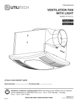
VENTILATION FAN
WITH EDGE-LIT LED
LIGHT
MODEL 7116-02
Español p.14
SM21617 READ AND SAVE THESE INSTRUCTIONS 10/2021
ATTACH YOUR RECEIPT HERE
Serial Number ___________________________ Purchase Date ___________________________
UTILITECH & logo design are trademarks or
registered trademarks of LF, LLC. All rights reserved.

2
TABLE OF CONTENTS
PRODUCT SPECIFICATIONS
Product Specications ........................................................................................................................2
Package Contents ..............................................................................................................................3
Hardware Included .............................................................................................................................3
Safety Information ..............................................................................................................................4
Preparation .........................................................................................................................................4
Installation Instructions .......................................................................................................................6
Care and Cleaning............................................................................................................................ 11
Troubleshooting ................................................................................................................................ 13
Warranty ...........................................................................................................................................13
Airow: 150 CFM LED light power consumption: 13W
120 V, 60 Hz LED light brightness: 1000 lumens dimmable
Duct diameter: 6 in. LED light color (CCT): 3000K Soft white
Sound output: 1.0 sone Weight: 10.1 lbs.
Fan power consumption: 36W (0.48A)

3
PART DESCRIPTION QUANTITY
A Fan housing 1
B Grille with LED light 1
C Duct adapter (optional) 1
D Suspension bracket 4
AB
C
D
HARDWARE INCLUDED (not shown actual size)
AA BB
Wood Screw Machine Screw
Qty. 8 Qty. 4
6 in. to 4 in.
PACKAGE CONTENTS

4
SAFETY INFORMATION
Please read and understand this entire manual before attempting to assemble, operate or install the product.
• Always disconnect the power supply prior to servicing
the fan, motor or junction box.
• Follow all local building, safety and electrical codes
as well as NEC (National Electrical Code) and OSHA
(Occupational Safety and Health Act).
• Electric Service supply must be 120 volts, 60 hertz.
• This product must properly connect to the grounding
conductor of the supply circuit.
• Do not bend or kink the power wires.
• Do not install in a ceiling with insulation greater than
R40.
• Duct work should be installed in a straight line with
minimal bends.
• Duct work size must be the same size as the discharge
and should not be reduced. Reducing the duct size
may increase fan noise.
• Do not use this fan with any solid state control device,
such as a remote control, or certain timers. Mechanical
timers are not solid state devices.
• This product is not intended for connection to rigid
metal conduit. For use with exible conduit only.
WARNING: To reduce the risk of re, electric shock,
or injury to persons, observe the following:
1. Use this unit in the manner intended by the
manufacturer. If you have any questions, please call
customer service.
2. Before servicing or cleaning unit, switch power off at
service panel and lock the service disconnecting means
to prevent power from being switched on accidentally.
When the service disconnecting means cannot be
locked, securely fasten a prominent warning device,
such as a tag, to the service panel.
3. Installation work and electrical wiring must be done by
a qualied person(s) in accordance with all applicable
codes and standards, including re-rated construction.
4. Sufcient air is needed for proper combustion and
exhausting of gases through the ue (chimney) of fuel
burning equipment to prevent backdrafting. Follow the
heating equipment manufacturer´s guideline and safety
standards such as those published by the National Fire
Protection Association (NFPA), and the American Society
for Heating, Refrigeration and Air Conditioning Engineers
(ASHRAE) and local code authorities.
5. When cutting or drilling into the wall or ceiling, do not
damage electrical wiring and other hidden utilities.
6. To reduce risk of re and to properly exhaust air, be
sure to vent air to the outdoors. Do not vent exhaust
air into spaces within walls or ceilings, or into attics,
crawl spaces, or garages.
7. If this unit is to be installed over a tub or shower, it must
be marked as appropriate for the application and be
connected to a GFCI (Ground Fault Circuit Interrupter) –
protected branch circuit.
8. This ventilation fan is intended to be installed at least
3.28 ft. (1 m) from the showerhead when installing over
a bathtub or shower. Installation within a shower stall
is not recommended for this unit, unless the 3.28 ft.
(1 m) distance can be met.
CAUTION
• For general ventilating use only. Do not use to
exhaust hazardous or explosive materials and
vapors.
• Not for use in kitchens.
• To reduce the risk of injury to persons, install the
fan at least 8.2 feet (2.5m) above the oor.
• To reduce risk of re and to properly exhaust air,
be sure to vent air to the outdoors. Do not vent
exhaust air into spaces within walls or ceilings,
or into attics, crawl spaces, or garages.
CAUTION: Installation of this unit requires the power to be OFF until installation is complete. If you encounter issues
with the unit not powering up, please review the troubleshooting section of the instruction manual. If you require additional
assistance, please call 1-866-994-4148, 8 a.m. - 8 p.m., EST, Monday - Sunday. You could also contact us at partsp-
[email protected] or visit www.lowespartsplus.com. DO NOT RETURN TO STORE.
PREPARATION
Before beginning assembly of product, make sure all parts are present. Compare parts with package contents list and
hardware contents. If any part is missing or damaged, do not attempt to assemble the product. Contact customer service for
replacement parts at 866-994-4148, 8 a.m. - 8 p.m., EST, Monday - Sunday. You could also contact us at
[email protected] or visit www.lowespartsplus.com.
Tools Required for Assembly (not included): Hammer, Flathead Screwdriver, Wire Connectors, Nails, Duct Tape, Phillips
Screwdriver, Electrical Tape, and Utility Knife or Drywall Saw.
Helpful Tools (not included): Electric Drill, Drill Bits
WARNING: RISK OF ELECTRIC SHOCK! Ensure the electricity to the wires you are working on is shut off. Either
remove the fuse or turn off the circuit breaker before removing the existing bath fan or installing the new one.

5
PREPARATION (Continued)
Check area above installation location to be sure that wiring can run to the planned location and that duct work can be run
and the area is sufcient for proper ventilation.
Inspect duct work and wiring before proceeding with installation.
Before installation, provide inspection and future maintenance access at a location that will not interfere with installation work.
You may need the help of a second person to install this fan: one person on the attic side and one on the room side.
Installation may vary depending on how the previous bath fan was installed. Supplies necessary for the installation of your
bath fan are not all included; however, most are available at your local home improvement or hardware store.
DIMENSIONS
Ceiling
Opening (L)
Ceiling
Opening (W)
Ceiling
Opening (H)
Housing
Dimension (L)
Housing
Dimension (W)
Housing
Dimension (H)
10 in. 10 in. 8-1/8 in. 9-5/8 in. 9-5/8 in. 7-7/8 in.
WIRING
It is recommended to apply proper insulation around the
fan to minimize heat loss and gain. This fan is designed to
be installed using a 6-in. duct.
Using a rigid duct is recommended. Using a exible duct,
cut to size and/or fully extended is also acceptable.
Ducting has a strong effect on the air ow, noise and
energy use of the fan. Use the shortest, straightest duct
routing possible for best performance. Avoid installing the
fan with smaller ducts than recommended. Insulation
around the ducts can reduce energy loss and inhibit mold
growth. Fans installed with existing ducts may not achieve
their rated air ow.
TYPICAL INSTALLATION
WARNING: Wiring must comply with all applicable electrical
codes. Turn off power before removing or installing connectors.
WARNING: COPPER TO COPPER ONLY. Do not use
aluminum wire.
CAUTION: Accessory part (quick connector) should meet
installation instructions below.
House
wires Product
wires
NOTE: The connector is reusable on solid wires of the same wire
gauge or smaller. Do not reuse the connector on stranded wires.
• Strip wires 3/8 in. - 1/2 in.
• Grip the wire rmly and push the stripped end of the wire into the open
port of the connector. Use only one conductor per port.
• Verify the stripped end of the wires is fully inserted to the back of the
connector.
CAUTION: Wiring maximum temperature rating 221˚F (105˚C).
600V maximum for building wiring and 1,000V maximum for signs
and light xtures. The acceptable wire range is 12-18 AWG Sol. Cu.
Quick connector
Fan housing
Properly insulate
around fan to
minimize building
heat loss and
gain
Seal any gap
around fan
housing 2-3 foot
straight run
before elbow
Short piece of
flexible duct helps
alignment and
absorbs sound
Roof cap
(with built-in
damper)
Caulk
termination
to duct
Wall cap
(with
built-in
damper)
OR

6
1. Remove existing fan.
If you are not replacing an existing fan, skip to step 3. 1
2. Measure the opening to ensure it is large enough to
accommodate the 9-11/16 in. x 9-11/16 in. dimensions of the new
fan housing (A).
2
3. If this fan is not replacing an old fan, be sure to cut a
10 in. x 10 in. opening for the fan housing (A).
IMPORTANT: One edge of the 10 in. x 10 in. cut out must be
along the joist for proper installation if the spacing between
joists is less than 12-3/4 inches.
3
INSTALLATION INSTRUCTIONS
BEFORE INSTALLATION
WARNING: RISK OF ELECTRIC SHOCK! Ensure the electricity
to the wires you are working on is shut off. Either remove the
fuse or turn off the circuit breaker before removing the existing
bath fan or installing the new one.
10"
10 "

7
4.
For spacing of less than 12-3/4 inches between ceiling joists:
Skip to step 11 if installing with spacing of 12-3/4 inches -
24 inches between ceiling joists.
Remove the three screws (4.1) on the side of the fan housing (A)
that hold the fan motor (4.2) in place. With the screws removed,
unplug the fan motor plug and pull the fan motor out of the fan
housing (A).
NOTE: Save the screws for reinstallation of the fan motor.
265.0000
A
4
5. Remove the duct connector (5.1) by removing the duct
connector screw (5.2) on the fan housing (A).
A
5.2 5.1
5
6. Remove the wiring box cover (6.1) from the fan
housing (A). Remove the wiring knockout (6.2) from
the wiring box cover (6.1) with a athead screwdriver.
6.2
6.1
6
INSTALLATION INSTRUCTIONS (Continued)
4.1
4.1
4.2
4.1
A

8
INSTALLATION INSTRUCTIONS (Continued)
7. Pull the house wires through the hole in the wiring box cover
(7.1). Using the quick connectors, connect the house wiring
from the wall switch to the fan housing (A). 14 AWG is the
smallest conductor that should be used for branch-circuit
wiring. Please refer to the wiring diagrams on page 5 to ensure
proper wire connections are made.
Carefully push the wire connections into the wiring box housing
and reattach the wiring box cover (7.1).
CAUTION: If your electrical wires do not match the colors
listed, consult a licensed electrician to determine what each
house wire represents before connecting the fan.
Quick
connector
7.1
7
8. Insert the fan housing (A) into the hole in the ceiling board (8.1).
Position the fan housing (A) so the bottom edge of the fan
housing (A) is ush with the ceiling board (8.1). Mount the fan
housing (A) to the joist with three wood screws (AA) through
the holes in the side of the fan housing (A).
Hardware Used
AA Wood screw x 3
Ceiling joist
Ceiling joist
AA
8.1
8.1
A
A
8
9. To attach the duct connector (9.1), pull the existing 6 in. circular
duct (9.2) into the fan housing (A). Connect the duct connector
(9.1) to the ducting using duct tape (not included) or a clamp
(not included) to create an air tight seal. Push ducting (9.2) back
through the fan housing (A) and secure the duct connector (9.1)
by sliding it into the slots in the fan housing (A) and securing it
with the screw that was removed in step 5.
Note: If the available ducting is 4 inches in diameter, the optional
duct adapter (C) can be attached to the duct connector (9.1) to
reduce the 6 in. duct connector (6.1) on the fan housing (A) to the
existing 4 in. ducting. Use duct tape (not included) or clamp (not
included) to secure the ducting to the adapter to create an air
tight seal.
9.2
9.1
A
C
9
8
A

9
INSTALLATION INSTRUCTIONS (Continued)
10. Plug the fan motor plug (10.1) into the fan housing (A). Place
the fan motor (10.2) back into the fan housing (A), aligning the
duct with the duct opening in the fan housing (A), and attach
the fan motor (10.2) to the housing using the three screws
(10.3) removed in step 4.
Skip to step 16 to complete the installation.
10.1
10..2
A
10
11.
For spacing of 12-3/4 - 24 inches between ceiling joists:
Insert two suspension brackets (D) into the tabs on each side
of the fan housing (A).
11
12. Insert the fan housing (A) into the opening in the ceiling. 12
10"
10"
A
A
Room-side new construction installation
Attic-side existing construction installation
D
A
D

10
INSTALLATION INSTRUCTIONS (Continued)
13. Position the fan housing (A) so the bottom edge of the fan
housing (A) is ush with the ceiling board. Do not ush mount the
fan housing (A) to the joist.
Attach the end of each of the suspension brackets (D) to the
ceiling joists using wood screws (AA).
Secure the suspension brackets (D) to the fan housing (A) using
the machine screws (BB).
Hardware Used
AA Wood screw x 8
BB Machine screw x 4 AA
D
A
BB
13
14. Remove the wiring box cover from the fan housing (A). Pull the
house wires through the hole in the wiring box cover (14.1).
Using the quick connectors, connect the house wiring from the
wall switch to the fan housing (A). 14 AWG is the smallest
conductor that should be used for branch circuit wiring. Please
refer to the wiring diagram on page 5 to ensure proper wire
connections are made. Carefully push the wire connections into
the wiring box and reattach the wiring box cover (14.1).
CAUTION: If the electrical wires do not match the colors listed,
you must determine what each house wire represents before
connecting the wiring. You may need to consult an electrical
contractor to determine how to make the electrical connections
safely.
Quick
connector
14
15 . Connect a 6 in. circular duct (15.1) to the duct connector (15.2) on
the fan housing (A), securing it with duct tape or a clamp. Vent the
duct to the outside.
Note: If available ducting is 4 inches in diameter, the optional
duct adapter (C) can be used to reduce the 6 in. duct connector
(15.2) on the fan housing (A) to the 4 in. ducting. Use duct tape
or a clamp to secure the ducting to the adapter to create an air
tight seal.
Joist
Joist
A
C
15
Joist
Ceiling joists
Ceiling board
1 4 .1
1 4 .1
15 .1
15.2

11
INSTALLATION INSTRUCTIONS (Continued)
16. Join the connectors (16.1) for the LED light from the fan
housing (A) to the grille (B). The grille (B) must be connected
before turning on power to the fan.
B
A
16
17. Attach the grille (B) by pinching the mounting springs and
inserting them into the narrow rectangular slots in the fan
housing (A).
Turn on power source. Test the unit.
B
A
17
CARE AND CLEANING
CAUTION: Before attempting to clean the xture, disconnect the power to the xture by turning the breaker off or
removing the fuse from the fuse box.
See safety information before proceeding. Routine maintenance should be done at least once a year.
• Never use solvents, thinner or harsh chemicals for cleaning the fan.
• Do not allow water to enter the motor.
• Do not immerse metal parts in water.
• Do not immerse resin parts in water more than 140°F.
WARNING: RISK OF ELECTRIC SHOCK! Ensure the
electricity to the wires you are working on is shut off. Either
remove the fuse or turn off the circuit breaker before removing
the existing bath fan or installing the new one.
Mounting
springs
Housing
slots
16 .1

12
CARE AND CLEANING (Continued)
1. Remove the grille (B) by squeezing the mounting springs and
pulling the grille (B) down from the fan housing (A). Disconnect
the connectors to remove the grille (B) from the fan housing (A).
Wipe grille (B) with a damp cloth.
1
B
A
2. Remove dust and dirt from the fan housing (A) with a vacuum
cleaner.
A
2
3. Wipe the fan housing (A) with a damp cloth and wipe dry.
A
3
4. Join the connectors for the LED light from the fan housing (A)
to the grille (B). Attach the grille (B) by pinching the mounting
springs and inserting them into the narrow rectangular slots in the
fan housing (A).
Turn on power source.
B
A
4
Mounting
springs
Housing
slots
Mounting
springs
Housing
slots

13
TROUBLESHOOTING
PROBLEM POSSIBLE CAUSE SOLUTION
The fan seems louder
than it should be.
The CFM is too great for the space. Be sure the CFM rating on the fan matches the
square footage of your room.
The damper is damaged or not working
properly. Check the damper to ensure it is opening and
closing properly. If the damper has become
damaged, please call Customer Service.
The bend in the duct is too close to the
fan discharge. Be sure you do not have any sharp bends in the duct
within 18 in. of the fan discharge.
The fan discharge is reduced to t a
smaller duct. Use the recommended size ducting to reduce fan
noise.
The fan body is not attached securely. Be sure the fan is securely attached to the ceiling
joists.
The fan is not clearing
humidity from the room.
There is insufcient airow intake in the
room. Be sure a door or window is slightly ajar or open to
allow airow. The fan is not able to draw air out of
the room without enough airow.
There is insufcient CFM.
NOTE: Using a tissue is not the
correct method for determining if the
fan is operating properly. If the fan
clears steam from the room within
approximately 15 minutes of completing
your shower, then the fan is operating
properly.
Be sure the CFM rating on the fan matches the
square footage of your room.
Printed in China
LIMITED 5-YEAR WARRANTY
If this product fails due to a defect in materials or workmanship at any time during the rst FIVE years of ownership, the
manufacturer will replace it free of charge, postage-paid at their option. This warranty does not cover products that have
been abused, altered, damaged, misused, cut or worn. This warranty does not cover use in commercial applications. Use
only manufacturer-supplied genuine warranty repair replacement parts to repair this fan. Use of non-genuine repair parts
will void your warranty. The manufacturer DISCLAIMS all other implied or express warranties including all warranties of
merchantability and/or tness for a particular purpose. As some states do not allow exclusions or limitations on an implied
warranty, the above exclusions and limitations may not apply. This warranty gives you specic legal rights, and you may
have other rights that vary from state to state.
This warranty is limited to the replacement of defective parts only. Labor charges and/or damage incurred during installation,
repair, replacement as well as incidental and consequential damages connected with the above are excluded. Any damage
to this product as a result of neglect, misuse, accident, improper installation or use other than the purpose SHALL VOID
THIS WARRANTY.
Shipping costs for return product as part of a claim on the warranty must be paid for by the customer.
Inquiries regarding warranty claims can be directed to 1-866-994-4148, 8 a.m. - 8 p.m., EST, Monday - Sunday. You could also
contact us at [email protected] or visit www.lowespartsplus.com.

14
ARTÍCULO # 0922557
VENTILADOR CON
ILUMINACIÓN LED
DE BORDE
MODELO 7116-02
¿Preguntas, problemas, piezas faltantes? Antes de volver a la tienda, llame a nuestro
Departamento de Servicio al Cliente al 1-866-994-4148, de lunes a domingos de 8 a.m.
a 8 p.m., hora estándar del Este. También puede contactarnos en [email protected]
o visitar www.lowespartsplus.com.
LEA Y GUARDE ESTAS INSTRUCCIONES
ADJUNTE SU RECIBO AQUÍ
Número de serie _________________________ Fecha de compra ________________________
UTILITECH y el diseño del logotipo son marcas
comerciales o marcas registradas de LF, LLC.
Todos los derechos reservados.

15
TABLA DE CONTENIDO
ESPECIFICACIONES DEL PRODUCTO
Especicaciones del producto .......................................................................................................... 15
Contenido del paquete .....................................................................................................................16
Materiales incluidos ..........................................................................................................................16
Información de seguridad .................................................................................................................17
Preparación ......................................................................................................................................17
Instrucciones de instalación ............................................................................................................19
Cuidado y limpieza ...........................................................................................................................24
Solución de problemas .....................................................................................................................26
Garantía............................................................................................................................................26
Flujo de aire: 150 CFM Consumo eléctrico del LED: 13 W
120 V, 60 Hz Brillo del LED: 1000 lúmenes regulable
Diámetro del conducto: 15,24 cm Color de luz LED (CCT): 3000K blanco suave
Volumen sonoro: 1,0 sone Peso: 4,58 kg
Consumo eléctrico motor: 36 W (0,48 A)

16
CONTENIDO DEL PAQUETE
PARTE DESCRIPCIÓN CANTIDAD
A Carcasa del ventilador 1
BRejilla con luz 1
C Adaptador para conductos (opcional) 1
D Soporte de suspensión 4
AB
C
D
MATERIALES INCLUIDOS (no se ilustran en tamaño real)
AA BB
Tornillo para
madera
Tornillo para
metales
Cant. 8 Cant. 4
15,24 cm a 10,16 cm

17
INFORMACIÓN DE SEGURIDAD
Por favor, lea y comprenda este manual en su totalidad antes de intentar ensamblar, operar o instalar el producto.
• Siempre desconecte la fuente de alimentación antes de darle
servicio al ventilador, motor o caja eléctrica.
• Siga todos los códigos locales de construcción, de seguridad
y eléctricos así como el NEC (Código Eléctrico Nacional) y
OSHA (Ley de Salud y Seguridad Ocupacional).
• El suministro eléctrico debe ser de 120 voltios, 60 hertz.
• Este producto debe estar correctamente conectado al
conductor de conexión a tierra del circuito de alimentación.
• No doble ni retuerza los cables de energía.
• No instale en un techo con aislamiento mayor de R40.
• Los conductos se deben instalar en una línea recta con
curvas mínimas.
• El tamaño del conducto debe ser del mismo tamaño que la
descarga y no debe ser reducido. Reducir el tamaño del
conducto puede aumentar el ruido del ventilador.
• No use este ventilador con dispositivos de control de estado
sólido, por ejemplo, un control remoto, un regulador de
intensidad o determinados temporizadores. Los temporiza-
dores mecánicos no son dispositivos de estado sólido.
• Este producto no está diseñado para conectarse a conductos
metálicos rígidos. Solo para uso con conductos exibles.
ADVERTENCIA: para reducir el riesgo de incendio,
choque eléctrico o lesiones a las personas, respete
lo siguiente:
1. Use esta unidad en la manera prevista por el fabricante. Si
tiene alguna pregunta, por favor llame al Servicio al Cliente.
2. Antes de dar servicio o limpiar esta unidad, apague la fuente
de alimentación en el panel y bloquéelo para evitar que se
encienda la alimentación accidentalmente. Si no puede
bloquear el panel, marque claramente el panel con una
etiqueta de advertencia para evitar que se encienda la
alimentación.
3. El trabajo de instalación y el cableado eléctrico debe ser
hecho por una persona calicada, de acuerdo con todos los
códigos y normas aplicables, incluyendo la construcción con
clasicación ignífuga.
4. Se necesita suciente aire para una combustión apropiada y el
escape de los gases a través del conducto (chimenea) del
equipo que quema combustible para evitar contratiraje. Siga
las guías del fabricante de equipo de calefacción y las normas
de seguridad como las publicadas de la Asociación Nacional
de Protección contra Incendios (NFPA), y de la Sociedad
Estadounidense de Ingenieros en Calefacción, Refrigeración
y Aire Acondicionado (ASHRAE), y las autoridades de
código local.
5. Cuando corte o perfore en la pared o techo, no dañe el
cableado eléctrico u otros servicios ocultos.
6. Para reducir el riesgo de incendio y extraer el aire de manera
adecuada, asegúrese de ventilar el aire hacia el exterior. No
extraiga el aire en espacios dentro de paredes o techos, o
en áticos, entrepisos o garajes.
7. Si esta unidad se va a instalar sobre una bañera o ducha,
se debe marcar según sea apropiado para la aplicación y
conectarse a un circuito de derivación protegido GFCI
(Interruptor de circuito de falla a tierra).
8. Este ventilador está diseñado para instalarse por lo menos a
1 m del cabezal de la ducha cuando se instala sobre una
bañera o ducha. La instalación dentro de una cabina de
ducha no se recomienda a menos que se pueda alcanzar
la distancia de 1 m.
PRECAUCIÓN
• Para uso de ventilación general solamente. No lo
use para desalojar materiales y vapores peligro-
sos o explosivos.
• No debe usarse en cocina.
• Para reducir el riesgo de lesiones a las personas,
instale el ventilador al menos a 2,5 m (8,2 pies)
sobre el piso.
• Para reducir el riesgo de incendio y extraer el
aire de manera adecuada, asegúrese de ventilar
el aire hacia el exterior. No extraiga el aire en
espacios dentro de paredes o techos, o en
áticos, entrepisos o garajes.
PRECAUCIÓN: la instalación de esta unidad requiere que la energía esté apagada hasta que se complete la instalación.
Si encuentra problemas con la unidad que no se enciende, revise la sección de solución de problemas del manual de
instrucciones. Si necesita asistencia adicional, llame al 1-866-994-4148, de lunes a domingos de 8 a.m. a 8 p.m., hora
estándar del Este. También puede ponerse en contacto con nosotros en [email protected] o visitar
www.lowespartsplus.com. NO REGRESE A LA TIENDA.
PREPARACIÓN
Antes de comenzar a ensamblar este producto, asegúrese de que todas las piezas estén presentes. Compare las piezas
con la lista de contenido del paquete y herraje incluido. Si hace falta alguna pieza o se encuentra dañada, no intente
ensamblar el producto. Póngase en contacto con el Servicio al Cliente para piezas de repuesto al 1-866-994-4148, de
lunes a domingos de 8 a.m. a 8 p.m., hora estándar del Este. También puede ponerse en contacto con nosotros en
[email protected] o visitar www.lowespartsplus.com.
Tiempo estimado de ensamblaje: 60 minutos
Herramientas necesarias para armar (no incluidas): martillo, destornillador de cabeza plana, conectores de cables,
clavos, cinta adhesiva, destornillador de estrella, y cuchillo multiuso o sierra para paneles de yeso.
Herramientas útiles (no incluidas): taladro eléctrico, brocas de taladro.
ADVERTENCIA: ¡RIESGO DE DESCARGA ELÉCTRICA! Asegúrese de cortar el suministro eléctrico en los cables
con los que trabajará. Extraiga los fusibles o apague el cortacircuitos antes de quitar el ventilador de baño
existente o instalar uno nuevo.

18
PREPARACIÓN (Continuación)
Compruebe el área sobre la ubicación de instalación para asegurarse de que el cableado puede correr a la ubicación
prevista y que los conductos se puede correr y el área es suciente para una ventilación adecuada.
Inspeccione los conductos y el cableado antes de proceder con la instalación.
Antes de la instalación, proporcione acceso para la inspección y el mantenimiento en un lugar que no interera con el
trabajo de instalación.
Es posible que necesite la ayuda de una segunda persona para instalar este ventilador; una en el lado del ático y otra en el
lado de la habitación.
La instalación puede variar dependiendo de cómo se instaló el ventilador anterior. Los suministros necesarios para la
instalación de su ventilador de baño no están todos incluidos; sin embargo, la mayoría está disponible en su tienda de
artículos del hogar o ferretería local.
DIMENSIONES
Apertura
de techo (La)
Apertura
de techo (An)
Apertura
de techo (Al)
Dimensiones
de caja (La)
Dimensiones
de caja (An)
Dimensiones
de caja (Al)
25,4 cm 25,4 cm 20,64 cm 24,44 cm 24,44 cm 20 cm
CABLEADO
ADVERTENCIA: el cableado debe cumplir todos los códigos
eléctricos aplicables. Desconecte la energía antes de retirar o instalar
los conectores.
ADVERTENCIA: COBRE A COBRE SOLAMENTE. No utilice
cables de aluminio.
PRECAUCIÓN: el accesorio (conector rápido) debe cumplir con
las instrucciones de instalación a continuación.
Conector rápido
Cables
de la casa Cables del
producto
NOTA: el conector es reutilizable en cables sólidos del mismo o
más pequeño calibre. No reutilice el conector en cables trenzados.
• Pele los cables de 9,52 mm a 1,27 cm.
• Sujete con rmeza el cable y empuje el extremo pelado del cable en el
puerto abierto del conector. Use solo un conductor por puerto.
• Verique que el extremo pelado de los cables esté completamente inserto
en la parte posterior del conector.
PRECAUCIÓN: temperatura máxima del cableado: 105 ºC (221 ºF).
Máximo 600 V para cableado de edicios y 1000 V máximo para
letreros y lámparas. El rango de cable aceptable es 12-18 AWG,
cobre sólido.
Se recomienda aplicar un aislamiento adecuado
alrededor del ventilador para minimizar la pérdida y
ganancia de calor. Este ventilador está diseñado para
instalarse con un conducto de 15,24 cm.
El conducto de este ventilador al exterior del edicio
tiene un fuerte efecto en el ujo del aire, ruido y uso
de energía del ventilador. Use la orientación del
conducto más corta y recta posible para un mejor
desempeño, y evite instalar el ventilador con conduc-
tos más pequeños que los recomendados. La insta-
lación alrededor de los conductos pede reducir la
pérdida de energía e inhibir el crecimiento de moho.
Es posible que los ventiladores instalados con con-
ductos existentes no logren su ujo de aire nominal.
INSTALACIÓN TÍPICA
Caja de unión Caja del interruptor
Negro
Blanco
Blanco
Azul
Verde
Interruptor
de luz
Interruptor
ventilador
En
En
Apagado
Apagado
Negro
Blanco
Puesta a
tierra (desnudo)
INTERRUPTOR DE
ENCENDIDO/APAGADO
se vende por separado)
Interruptor
e luz Interruptor
de alimentación
Azul
Caja del
interruptor
Entrada de línea
de 120 V CA
Empalme plástico
(no se incluye)
Placa de
cableado
Conector rápido
(se incluye)
Carcasa del
ventilador
Aísle adecuadamente
alrededor del
ventilador
para minimizar la
pérdida y ganancia
de calor del edificio
Las piezas cortas
de conducto
flexible ayudan a
alinear y absorber
el sonido
Tapa de techo
(con amortiguador
incorporado)
Calafatear la
terminación
al conducto
Tendido recto
de 61 a 91 cm
antes del codo
Selle cualquier
espacio alrededor
de la carcasa
del ventilador
Tapa de
pared (con
amortiguador
incorporado)
O

19
1. Retire el ventilador existente.
Si no está reemplazando un ventilador existente, vaya al
paso 3.
1
2. Mida la abertura para asegurarse de que sea lo sucientemente
grande para acomodar las dimensiones de 24,59 cm x 24,59 cm
de la carcasa del nuevo ventilador (A). 2
3. Si este ventilador no reemplaza a uno viejo, asegúrese de cortar
una abertura de 25,4 cm x 25,4 cm para la carcasa del ventilador
(A).
IMPORTANTE: Un borde del corte de 25,4 x 25,4 cm debe
estar a lo largo de la viga para una instalación adecuada si el
espacio entre las vigas es menor de 32,4 cm.
3
INSTRUCCIONES DE INSTALACIÓN
PREVIO A LA INSTALACIÓN
ADVERTENCIA: ¡RIESGO DE DESCARGA ELÉCTRICA!
Asegúrese de cortar el suministro eléctrico en los cables
con los que trabajará. Extraiga los fusibles o apague el
cortacircuitos antes de quitar el ventilador de baño existente o
instalar uno nuevo.
25,4 cm
25,4 cm

20
4.
Para un espacio de menos de 32,39 cm entre las vigas del
techo:
Vaya al paso 11 si instala con un espacio de 32,39 cm a
60,96 cm de espacio entre las vigas del techo.
Quite los tres tornillos (4.1) en el lado de la carcasa del ventilador
(A) que hace un agujero al conjunto del motor del ventilador (4.2).
Desenchufe la unidad de alimentación del ventilador (A). Retire
el conjunto del enchufe del motor del ventilador de la carcasa del
ventilador (A).
NOTA: guarde los tornillos para reinstalar del motor del ventilador.
265.0000
A
4
5. Retire el conector de conducto (5.1) extrayendo el tornillo del
conector de conducto (5.2) en la carcasa del ventilador (A).
A
5.2 5.1
5
6. Retire la cubierta de la caja del cableado (6.1) de la carcasa
del ventilador (A). Retire el oricio ciego del cableado (6.2) de
la cubierta de la caja del cableado (6.1) con un destornillador
de cabeza plana.
6.2
6.1
6
INSTRUCCIONES DE INSTALACIÓN (Continuación)
4.1
4.1
4.2
4.1
A
/