Page is loading ...

Wallduct Bodies & Fittings
INSTALLATION INSTRUCTIONS
Installation Instruction No.: 1 002 623 – January 2003
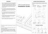
Wall Surface
Thru Surface Wallduct
Thru Flush Wallduct
Walker
®
electrical systems conform to and should be properly
grounded in compliance with requirements of the current National
Electrical Code or codes administered by local authorities.
All electrical products may present a possible shock or fire
hazard if improperly installed or used. Walker electrical products
may bear the mark as UL Listed and/or Classified and should
be installed in conformance with current local and/or the National
Electrical Code.
IMPORTANT – PLEASE READ ALL INSTRUCTIONS BEFORE BEGINNING.
Products Covered: Steel and aluminum raceway bodies, fittings, and accessories with catalog numbers beginning with the
following prefix: WD, AWD, CP, ACP, VA, or AVA.
Wall
Stud
Raceway and fittings may be mounted directly to a wall/ ceiling surface, or mounted within the wall/ ceiling so
that the cover plate is flush with the mounting surface (see illustration below).
Mounting means and hardware are not provided. Raceway and fittings must be secured to the mounting surface
at intervals not exceeding 4 feet [1.2m] when wall mounted vertically or horizontally with a minimum of 4 drywall
screws with a length of 2.00" [5.08cm] with a coarse thread pattern. A spacing of 2 feet [.610m] is recommended.
The portion of the fastener that resides inside the raceway must be free of sharp edges or any surfaces that may
abrade the internal cabling. Mounting holes must be field drilled into the raceway and fittings. Make sure screws
applied meet your specific load applications and that the mounting surface material will support the load of the
raceway and fittings, and the additional load of the internal cabling. When mounting from a ceiling, consult
manufacturer of support means to make sure load applied can be properly supported. In order to do this you
must calculate the wire and duct weight over the desired distance between supports.
When assembling adjacent sections of raceway and fittings together using the coupling angles and hole locations
provided, screws must be tightened to a torque of 35 inch-pounds [3.953 Nm]. Use a #18 drill, diameter of .170"
[4.31mm] for field drilled hole locations where #10-32 taptite screws are being used. Suggested torque value for
taptite screws is 25 inch-pounds [2.823Nm]. For coverplates or other locations where palnut clips are to be used,
a hole of 9/32" [7.143mm] is required. Cover plates must be secured to the raceway and fittings with the screws
provided to a torque value of 30 inch-pounds [3.388 Nm].
All field cut edges or corners must be filed smooth or a grommet added to prevent damage to internal cabling and
personal injury. The installer must take special care when installing internal tunneling and partitions to prevent any
gaps or openings greater than 1/16" [1.59mm] in width.
Raceway and fittings must be grounded in accordance to the NEC and any other local codes that apply. Any paint
that is applied to the raceway must be removed in the locations where the grounding means (not provided by Walker
Systems, Inc.) is attached. Raceway system is intended for power conductors 4/0 or smaller and circuits operating
at potentials not exceeding 600 volts between conductors.

Step 1 Bodies need to be butted together using
coupling angles provided and #10-32 "taptite"
screws. All screws are required for proper
electrical bonding between bodies and
attachment to wall.
Step 2 With bodies connected and mounted to wall
with screws, place partitions into duct as
necessary making sure wire fill requirements
are followed as per NEC (Wire fill information
is also located onlast page of instruction sheet).
Step 3 Place wires into duct and then slide wire
retainers into place (wires not shown for
clarity). The wire retainer fits in slots located
at the end of each duct body and in the
middle of a 60" [1,524mm] body.
Step 4 To attach cover, place palnut clip over holes
on top side of duct as shown. Position cover
and secure into place using #10-32 machine
screws provided.
Palnut Clip
SPECIFIC INSTRUCTIONS: STRAIGHT BODIES AND THEIR COMPONENTS
Follow the instructions on page 1 for surface mounting application. Bodies are supplied from factory with wire
retainers, coupling angles, and necessary fasteners. Fasteners to mount bodies to wall are supplied by installer.
Access cover plates not shown here are installed similar as described for cover plates shown below. Apply
supplied grommet to access cover plates.

Step 1 For Reducer Couplings – Place one reducer
onto the inside of the duct and attach as you
would a coupling angle. Repeat for the other
reducer coupling as necessary.
Step 1 For End Closures – Fasten closure to body of
duct using screws provided. The closure should
be attached just like a coupling angle.
Step 1 For Flanged Cabinet Connectors –
Connect flanged cabinet connector using
coupling angles and screws provided
(similar to connecting two pieces of straight
wallduct). Attach to cabinet using holes
provided and approporiate screws (provided
by others).
Step 1 For VA Risers – Attach riser to duct body using
coupling angles provided with duct body and
attach to trench body using screws provided
through tabs provided with the VA body.
SPECIFIC INSTRUCTIONS: REDUCER COUPLINGS, END CLOSURES, FLANGED CABINET CONNECTORS,
AND VA RISERS.
Reducer couplings are used for transitions from a larger to a smaller width duct of the same depth. End closures
are used to close end of duct. Both are attached using #10-32 taptite screws. Flanged cabinet connectors connect
duct bodies to cabinets of various sizes. VA Riser transition trenchduct to wallduct. All screws are required for
proper electrical bonding.
NOTE: This should be done prior to installation of any wires,
coverplates, and wire retainers.
NOTE: When transitioning from a larger duct body to a smaller
duct body, follow all wire fill requirements according to
UL and the last page of this instruction sheet.

Step 1 For T-Units, X-Units, and Elbows – Unit
attaches with coupling angles similar to
standard wallduct bodies (page 2). Make
sure to use proper screw torque when
connecting bodies.
Step 1 For 2 Compartment X-Units Tunnels –
Position tunnel in X-Unit as shown before wiring
is installed. Using holes in the tunnel flange as
a guide, drill .170" dia. (#18 drill, [4.318mm])
holes through the bottom of the X-Unit.
Step 1 For 3 Compartment X-Unit Tunnels – Follow
previous instructions for X-unit tunnels. If the
partition of the adjoining wallduct sections
have not been installed prior to the assembly
of the X-unit tunnels / bridges, cut the partition
long enough to extend into the X-Unit and
abut the tunnel/bridges as shown.
If the partitions of the adjoining Wallduct
sections have been installed prior to the
assembly of the X-unit tunnels/bridges, cut
the partition pieces from excess straight body
partitions, as shown below. These pieces are
required to fit between the straight body
partitions and the tunnel / bridges of the X-unit.
When bridges overlap tunnels, secure the
bridge to the tunnel with a 3/16" pop rivet
(provided by others). Use the hole(s) located
in the bridge as a guide to drill a 13/64" [5.16
mm] diameter hole for the pop rivet. Select a
pop rivet length suitable for the tunnel material
thickness installed.
SPECIFIC INSTRUCTIONS: T-UNITS, X-UNITS, ELBOWS, AND COMPARTMENT TUNNELS
T-Units, X-Units, and Elbows are used for multiple runs of duct that come together in the same location or to make
a sharp turn at the end of one run and the beginning of another. Compartment tunnels are used to run different
feeds (power and communication, ex.) through the same duct bodies. Internal, external, and sweep elbows not
shown here are installed similar to T-Units shown below.
NOTE: Make sure to follow all bend radius requirements when
installing wires into duct.
NOTE: Using tunnels reduces your overall wire fill capacity by 50%
due to reduced area for wires in the system as a whole.
Bridge
Tunnel
Bridge
Partition
Tunnel

Step 1 For 2 Compartment T-Unit Tunnels –
Position T-Unit as shown before wiring is
installed. Using holes in the tunnel flange as
a guide, drill .170" dia. (#18 drill, [4.318mm])
holes through the bottom of the T-Unit.
Mount the tunnel with the #10-32 self
tapping screws provided.
Step 2 For 2 Compartment T-Unit Tunnels – If the
partition of the adjoining Wallduct sections
have not been installed prior to the assembly
of the T-unit tunnels/bridges, cut the partition
long enough to extend into the T-Unit and abut
the tunnel/bridges as shown.
Step 3 For 2 Compartment T-Unit Tunnels – If the
partitions of the adjoining Wallduct sections
have been installed prior to the assembly of
the T-unit tunnels/bridges, cut the partition
pieces from excess straight body partitions,
as shown below. These pieces are required
to fit between the straight body partitions
and the tunnel/bridges of the T-unit.
Step 1 For 3 Compartment T-Unit Tunnels –
Follow steps 1 through 3 above. When
bridges overlap tunnels, secure the bridge
to the tunnel with a 3/16" pop rivet. Use the
hole(s) located in the bridge as a guide to
drill a 13/64" [5.16 mm] diameter hole for the
pop rivet. Select a pop rivet length suitable
for the tunnel material thickness installed.
SPECIFIC INSTRUCTIONS: T-UNIT TUNNELS
Three and four compartment tunnels are used where duct bodies come together. Compartment tunnels are used to
run different feeds (power and communication) through the same duct bodies. Installation is similar for both three
and four compartment tunnels as shown below in detail.
NOTE: Using tunnels reduces your overall wire fill capacity by 50%
due to reduced area for wires in the system as a whole.
Partition
Tunnel
Partition
Tunnel
Partition
Tunnel
Bridge

Step 2 Drill four holes with a diameter of 9/32" [7.144mm]
to match with ceiling drop out mounting holes.
This can be best achieved by placing the drop
out onto duct body and marking with a marker
or pencil. These are the locations for the palnut
clips and machine screws.
Step 3 With cutout and holes made, place drop
out unit into body from top and screw into
place with palnut clips and #10-32 machine
screws. This installation is similar to that
of a coverplate.
Step 4 Adjust depth of drop out by loosening and
tightening the four #10-32 taptite screws on the
side of the unit until it sits flush as desired. Cut
desired hole size into drop out coverplate. Place
grommet supplied around field cut hole.
SPECIFIC INSTRUCTIONS: CEILING DROP OUT UNITS
Ceiling drop outs are intended for use with 10" [254mm] wide wallduct. The primary purpose is to allow wallduct
to sit flush with ceiling. Grommet all sharp edges to prevent wires from being damaged.
Step 1 With desired location selected, cut a hole
into bottom side (center) of duct body 8.75"
[222.25mm] wide and 8.75" [222.25mm] long.
NOTE: File all sharp edges and burrs on the wallduct that may cut
wire insulation.

Step 1 For Cabinet Connectors – Remove cover
from unit, retain all fasteners.
Step 2 Fasten unit to duct body. Holes for connection
will need to be drilled in the straight body flanges
as necessary using a 9/32" [7.14mm] diameter
bit. Use the holes in the sweep cabinet connector
as a guide to drill the holes. Place palnut clips
over drilled holes. Re-position cabinet connector
to line up with palnut clips. Secure into place
using #10-32 machine screws provided.
Step 3 Attach cabinet connector to unit by adjusting
bottom to sit flush with cabinet and then
fasten with approporiate screws (provided
by others).
Step 4 Place wires and attach cover onto body with
screws provided.
SPECIFIC INSTRUCTIONS: SWEEP CABINET CONNECTORS
Cabinet connectors are used for applications to connect wallduct to electrical cabinets such as those in MRI rooms.

Step 2 For Flush to Surface Transition – With
coverplate area prepared, apply grommet to
all sharp edges, place wires and wire retainers,
and attach transition with planut clips and
#10-32 machine screws provided.
Step 1 For Sweep Tees – Remove cover of sweep
tee unit and save screws. Attach unit to duct
body using coupling angles and #10-32
taptite screws provided. Refer to page 2 for
similar mounting methods.
Step 2 For Sweep Tees – Attach unit to the other duct
body using #10-32 machine screw and palnut
clips provided. Refer to instructions shown in
step 2 of previous page for attachment method.
SPECIFIC INSTRUCTIONS: FLUSH TO SURFACE TRANSITIONS AND SWEEP TEES
Flush to Surface transitions are used for changing covers of duct bodies to a flush or surface application. Sweep
tees are used for changing directions of the duct body or adding a perpendicular duct in the middle or at the end
of a straight duct.
Step 1 For Flush to Surface Transition – In desired
location, field cut cover to allow for transition
to fit onto duct body. Refer to instructions
shown in step 2 of previous page for
attachment method.

Step 1 With desired location selected, cut a hole
into bottom side (center) of duct ceiling body
9 13/16" [249.24mm] wide and 3 3/16"
[80.96mm] long for a standard 10" [254mm]
wide by 3 1/2" [88.9mm] deep drop out.
Adjust hole size accordingly for non-
standard drop out units.
Step 2 Drill four holes with a diameter of 9/32"
[7.144mm] to match with ceiling drop out
mounting holes. This can be best achieved by
placing the drop out onto duct body and marking
with a marker or pencil. These are the locations
for the palnut clips and machine screws.
SPECIFIC INSTRUCTIONS: DROP OUT UNITS
Drop out units are to be used for transitioning to cabinet or a perpendicular duct run.
Step 3 Place drop out unit into body and screw
into place with palnut clips and #10-32
machine screws. Installation is similar to
that of a coverplate.
Step 4 Attach the other duct body to drop out using
screws and coupling angles provided. Run
wires, wire retainers and close duct bodies
as necessary.

Deduct for Deduct for
DEDUCT FOR DEDUCT FOR
MATERIAL THICKNESS MATERIAL THICKNESS
MAXIMUM RACEWAY (LEFT & RIGHT) (BOTTOM)
WIDTH (In.) Inches [mm] Inches [mm]
6" – 18" [15.2 – 45.7cm] Steel 0.156" [3.962] 0.078" [1.981]
20" – 30" [50.8 – 76.2cm] Steel 0.216" [5.486] 0.108" [2.7432]
6" – 18" [15.2 – 45.7cm] Aluminum 0.200" [5.080] 0.100" [2.540]
20" – 30" [50.8 – 76.2cm] Aluminum 0.250" [6.35] 0.125" [3.175]
WIREFILL AND IMPORTANT UL INFORMATION
Use these steps to determine Wirefill Capacity
Step 1: Determine the internal raceway area by multiplying the overall width by the overall depth (subtract
material thickness).
Example: Assume you have a steel raceway 10" wide by 4" deep [254mm wide by 101.6mm deep].
Subtract the material thickness from each dimension (see Table 2). This results in an internal
raceway dimensions of 9.844" [250mm] (10" – 0.156" [ 254mm – 3.96mm]) wide by 3.922" [100mm]
(4” – 0.078" [101.6 – 1.98mm]). The internal area for this raceway size would be 38.6 sq.in.
[249.03cm
2
] (9.844" x 3.922").
Step 2: Determine the number of conductors allowed inside the raceway for a given type and size (types THHN
and THWN are shown in Table 1) of conductor by multiplying the internal area (calculated in Step 1) by
the number of conductors allowed per square inch (see Table 1).
Example: Assume you want to calculate how many No. 6 AWG (THHN) conductors you are allowed
to place in the 10" by 4" [254mm x102mm] raceway in step 1 at 40% wire fill capacity. Multiply the
internal area of the raceway by the maximum number of wires allowed per square inch, from Table 1.
This results in 304 allowable cables (38.6 sq. in. x 7.89 [249.03cm
2
x 7.89]).
THHN/THWN APPROXIMATE APPROXIMATE 20% FILL 40% FILL
WIRE SIZE OUTSIDE DIAMETER AREA (Per In.
2
) (Per In.
2
)
GAUGE NO. In. [cm] In.
2
[cm
2
] [6.45cm
2
] [6.45cm
2
]
14 0.111 [.2819] 0.0097 [.0625] 20.62 41.24
12 0.130 [.3302] 0.0133 [.0851] 15.04 30.08
10 0.164 [.4166] 0.0211 [.1361] 9.48 18.96
8 0.216 [.5486] 0.0366 [.2361] 5.46 10.93
6 0.254 [.6452] 0.0507 [.3271] 3.94 7.89
4 0.324 [.8230] 0.0824 [.5316] 2.43 4.85
3 0.352 [.8941] 0.0973 [.6278] 2.06 4.11
2 0.384 [.9754] 0.1158 [.7471] 1.73 3.45
1 0.446 [1.1328] 0.1562 [1.0077] 1.28 2.56
1/0 0.486 [1.2344] 0.1855 [1.1968] 1.08 2.16
2/0 0.532 [1.3513] 0.2223 [1.4343] 0.90 1.80
3/0 0.584 [1.4834] 0.2679 [1.7285] 0.75 1.49
4/0 0.642 [1.6307] 0.3237 [2.0885] 0.62 1.24
TABLE 1
TABLE 2
A 20% fill should be used for systems utilizing fittings that have sharp 90º turns. The derating factors of NEC
article 310.15(B)(2)(a) shall apply to conductors installed if the amount of current-carrying conductors exceeds
30 in number, or the sum of the cross-sectional area of all conductors exceeds 20 percent of the interior
cross sectional area of the raceway. When tunnels are utilized, the internal cross sectional area must be
further reduced by 50 percent. When partitions are utilized, the internal cross sectional area must be calculated
for each individual compartment.


The Wiremold Company
U.S. and International:
60 Woodlawn Street • West Hartford, CT 06110
1-800-621-0049 • FAX 860-232-2062 • Outside U.S.: 860-233-6251
Canada:
850 Gartshore Street • Fergus, Ontario N1M 2W8
1-800-741-7957 • FAX 519-843-5980
1 002 623 0103
© Copyright 2003 The Wiremold Company All Rights Reserved
/