Page is loading ...

P-500AL-4 "PairStand"
instructions manual
(ver.4.0 2013/3)
!
FEATURES
● Save vast amounts of space by storing
two bicycles in a single space.
● Alloy pillar is light weight and rust proof,
but durable. Max load is 100 kgs.
● Legs are switchable between K-style
and X-style depending on the number of
bikes or setup location.
● Updated alloy clamp securely holds
the cradle and allows for easy position
changes.
● The bike hook is designed to be low
prole to get the bike on and o easily.
Soft plastic pads prevent frame from
being scratched. It ts up to 70mm
diameter frame.
● Individually angle adjustable arm ts any
type of bike frame.
CAUTIONS
●
For normal 2-wheel bicycle only. Tandem,
recumbent and long tail bikes may not be
used on this stand. Place heaviest bike in the
lower cradle to maintain stands balance.
●
Set stand on an even, horizontal oor. Adjust
each foot precisely to insure each of the
foot's four points touch the oor evenly.
●
Leaving a bike in the top cradle only may
cause an imbalance and the stand could fall
down. Be careful to keep weights balanced
at all times.
●
Do not hook the bike with the down-tube and
seat-tube. Hook the top-tube.
●
The clamp is made of light alloy material.
Do not over- tighten or the bolt may come
out of the housing, ruining the clamping
mechanism.
(Image: P-500AL-4 in K-style leg)
●
Follow the correct order for tightening the screws. Failure to do so may lead to improperly tightened screws.
●
When you setup the legs in K-style, the stand should be placed next to a wall to prevent the stand from tipping over
backwards. Do not install any optional attachment on the backside of the pillar to maintain a safe balance.
When you setup the legs in X-style, these won't be a problem.
Contact
MINOURA JAPAN MINOURA NORTH AMERICAN TECH CENTER
(for ALL customers, including Canada) (for U.S. residents ONLY)
1197-1 Godo, Anpachi, Gifu 503-2305 Japan Mon - Fri, 9 am - 5 pm (PCT)
Fax +81-584-27-7505 Phone 1-510-538-8599 / Fax 1-510-538-5899
If you have question or problem on this product, please contact the shop where you originally purchase this product
or the distributor in your country first. The distributor information can be found on our web site. Only when you
cannot obtain enough service from them, you can contact Minoura directly.
Made in Japan

- 2 -
Assemble P-500 in K-style Leg
Required Tools
1 x M5 Hex Wrench
(included)
1 x Phillips Screwdriver
(not included)
1 x 13mm Spanner
(not included)
Pillar
Hook
Arm
Long Leg
Short Leg
Foot Adjuster
Cradle
{
1
2
3
(Fig. B)
(Fig. C)
(Fig. D)
(We strongly recommend to use the fatter No.3
screwdriver instead of standard No.2)
How To Read Bolt Size
Length
Diameter
Ex) 6 x 30
Part Name
Setting up your P-500 in the K-Style leg conguration saves valuable room
because the stand can be placed next to a wall. ONLY place the bikes on
the front side of the stand so as to maintain balance and keep the stand
from toppling over. Maximum bikes per stand is TWO (2).
Attach two Leg Brackets to the
Pillar.
One is set directly, and another
one is set beyond the silver
Collars.
Do not tighten the M6x70 Bolts
firmly yet. (see Fig. B)
Pillar
Leg Bracket
(both are exactly same)
Collar (Silver)
M6x70 Bolt
Spring Washer
Screw the bolts to
these slots
(Fig. A)
Put the black Collars to the designated holes (see Fig. D) on
both Long and Short Legs. Collar is put from the larger hole.
Collar (Black)
(Fig. E)
Place the legs as shown in Fig.E.
Diameter Length
Long Leg
Short Leg
The collar works to prevent deforming the tube
by the bolt tightening power. You must set
the collar correctly.

Inside layout is as shown in Fig.F.
You will install short Legs first, so you don't have to
set Long Leg at this moment.
(Fig. F)
4
Put the longer M6x70 Bolt to the end hole on the
Short Leg, then screw it into the Pillar.
(Fig. G)
M6x70 Bolt
Spring Washer
5
Put the shorter M6x45 Bolt into the corner hole to fix
the Long and Short Legs. M6x45 Bolt will be screwed
to the Dome Nut.
M6x45 Bolt
Spring Washer
Dome Nut
6
- 3 -
Tighten every bolt.
Over-tightening the M6x70 Bolt may cause serious
damage to the alloy Pillar. Do not overtighten.
(Fig. H)
(Fig. I)
Assemble P-500 in X-style Leg
Setting up the P-500 in the X-style allows the stand to
1
Put 4 black Collars to the designated holes on the
Long Leg. Sandwitch the Long Leg with 2 Leg
Brackets, then attach to the Pillar.
(Fig. J)
be placed anywhere due
to the larger footprint and
maximum stability of the X.
It also allows you to install
extra bike cradles and/or
optional attachments on the
back side (max number of
bikes is 4).
Pillar
Long Leg
Collar
(Black)
M6x45 Bolt
Spring Washer
M6x70 Bolt
Spring Washer
M6x45 Bolt
Spring Washer
Dome Nut
(Fig. K)
Use the longer M6x70 Bolts
to the center 2 holes for
screwing into the Pillar.
Use the shorter M6x45 Bolts
to the outer holes, then screw
to the Dome Nuts.
Every bolt should not be
tightened firmly yet.
This is the image after every bolt is screwed in.
(Fig. L)
(Fig. M)
Please note, setting the stand up in the
X-style does require more oor space.
Leg Bracket
(both are exactly same)
Screw the bolts
to these slots

2
Put the black Collars to all holes on the Short Leg.
Collar must be inserted from the larger hole.
- 4 -
3
Set the Short Legs as they make "X" shape.
(Fig. N)
(Fig. O)
(Fig. P)
Inside layout is as shown in Fig. P.
Long Leg
Collar (Black)
Short Leg
4
Put the longer M6x70 Bolt to the end hole on the
Short Leg, then screw into the Pillar.
(Fig. Q)
M6x70 Bolt
Spring Washer
5
Put the shorter M6x45 Bolt to other hole, sandlwich
the Short Leg with two Leg Brackets, then screw to
the Dome Nut.
M6x45 Bolt
Spring Washer
Dome Nut
(Fig. R)
(Fig. S)
6
Tighten every bolt.
Over-tightening the M6x70 Bolt may cause serious
damage to the alloy Pillar. Do not overtighten.
Short Leg
Short Leg

- 5 -
Schematic of Cradle
Left Side Arm
(Front Side)
Right Side Arm
(Back side)
Cradle Cap
Hook
Base Plate
Alloy Clamp
Metal Collar
(Left side only)
Pivot-Pin
Pivot-Pin Fixing Bolt
Hook Fixing Bolt
Left side Arm Angle
Fixing Bolt
Right side Arm Angle
Fixing Bolt
Arm Connecting
Bolt
Clamp
Tightening
Bolt
●
Two Bike Cradles are exactly same.
●
Arm on P-500AL-4 is the bent type which is different from the one found on BikeTower10. This design allows to
place the bike a little further from the Pillar to help prevent scratching.
The same cradle is sold separately under the name of "Bike Cradle 4". Use this type for adding attachment.
Install Bike Cr
adle to
P-500
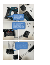
The clamp band is pre-installed
on the pillar and it's temporally
tightened. Change the clamp
position to your favorite location.
Bike Cradle can be set at any
height and any angle on the Pillar,
but you must set it on the front
side only on P-500, not angled,
when you setup in K-style leg.
!
To change the clamp position, loosen 1) the clamp tightening
bolt and 2) the pivot-pin fixing bolt by the supplied M5 hex
wrench, then 3) slide gently.
Loosen both bolts to adjust, not only the
Clamp Tightening Bolt.
!
The bike cradle MUST only be installed on
the front side. Failure to do so will cause the
stand lose balance and possibly topple over.
After adjusting, tighten BOTH bolts firmly.
!
The clamp band may scratch the pillar
if adjusted height roughly. Use caution
when moving the band.
1
(Fig. T)
1
2
3
(Fig. U)
Install the Hooks to the pre-assembled bike cradle. Attach
the Hook from the foreside of the Arm.
Next, install the bike cradle to the Alloy Clamp.
Make sure there is a rectangle hole on the backside of the
Base Plate. It will be connected to the Clamp body.
Tighten the Arm Connecting Bolt (hidden in the plastic cap)
through the center hole on the Cradle Cap until the bike
cradle is rigidly installed.
!
2
If it's hard to screw the Arm Connecting
Bolt, you can loosen both bolts on the clamp
slightly. It should make the job easier.
When tightening the bolt to install the Bike
Cradle onto the Clamp body, screw it gently
in the beginning at least 3 rotations, then
tighten by using a tool. If you use the tool
from the beginning, you may break the
thread that means you will need to buy and
replace the clamp.
!
(Fig. V)

- 6 -
The arms are independently angle adjustable in the range of
+/- 35 degrees in order to fit to various types of bike frame
as perfectly as possible.
!
We do not recommend you to set both arms
upright.
You should set the arm which supports main
load to horizontal or lower angle.
!
If the bolts are not rmly tightened, the arms
may move and cause the bike to fall off the
hooks.
Make sure the bolts are tightened correctly.
To change the arm angle, loosen the Arm Connecting Bolt
through the center hole first, loosen the backside Arm Angle
Fixing Bolt on each arm, then change the arm angle by
hand.
After adjusting, make sure you tighten both center and
backside bolts firmly.
3
Mount Your Bike
To mount your bike on P-500AL-4, place the hooks under
the crossing sections of the frame tubing.
You should set the hook distance as wide as possible for
greatest stability.
On a normal diamond type frame, you will hook the top-
tube with both hooks, but in the case of sloping frame or
other specially designed frame, you can change to another
point such as behind the seat-tube to avoid slippage problem.
Choose the most stable section for maximum safety.
!
If the bikes front wheel is placed higher than
the rear, the front wheel may move side-to-
side.
This could cause incidental damage to your
bike if the handle bars or brakes or other
parts come in contact with your frame.
Adjust the bike accordingly to avoid
incidental contact. Or we strongly
recommend you to connect the front wheel
and the down-tube with a strap belt.
(Fig. W)
(Fig. X)
(Fig. Y)

How To Reinstall Clamp Band
The clamp bands come pre-installed and they should not
need to be removed. However, there may come time when
adding options to P-500AL-4 that you will need to remove
them.
Install the clamp peoperly as instructed below. Failure to do
so may cause parts damage or bike falling off accident.
Wind the clamp arms around
the Pillar.
The following description is
set as the single side arm is on
YOUR right, and the double
side arm is on YOUR left.
Put the Pivot-Pin through all 3 holes
on the clamp band from bottom side,
and screw the Pivot-Pin Fixing Bolt
with a flat washer temporally.
!
Make sure to insert the
Pivot-Pin from the bottom.
If you don't, you will not
be able to tighten the bolt
using a hex wrench.
Pillar
Turn the Pivot-Pin to align the thread
hole to the side hole on the clamp
band.
Screw the Clamp Tightening Bolt into
the Pivot-Pin.
To fix the clamp band firmly, tighten
the Clamp Side Pin first then tighten
the Pivot-Pin Fixing Bolt later.
!
Do not tighten the Pivot-
Pin Fixing Bolt rmly yet.
The next job will become
difcult.
1
2
3
- 7 -
(Fig. Z)
(Fig. AA)
(Fig. AB)
Using Black Round Decal
(Fig. AC)
If you wish to hide the holes beside the Leg Bracket when
setting up in K-style leg configuration, put the supplied
black round decal onto the hole.
You will not use them when setting up in X-style.
Black Round Decal
/