Page is loading ...

05/18/06
Freestanding Gas Stove
FOR YOUR SAFETY
What to do if you smell gas:
Do not try to light any appli-
ance
Do not touch any electri-
cal switch: do not use any
phone in your building.
Immediately call your gas
supplier from a neighbour's
phone. Follow the gas sup-
plier's instructions.
If you cannot reach your
gas supplier, call the fi re
department.
WARNING:
Improper installation, adjustment, altera-
tion, service or maintenance can cause
injury or property damage. Refer to this
manual. For assistance or additional in-
formation consult an authorized installer,
service agency or the gas supplier.
FOR YOUR SAFETY
Do not store or use gasoline or other fl am-
mable vapours and liquids in the vicinity of
this or any other appliance.
Installation and service must be performed
by an authorized installer, service agency or
the gas supplier.
PLEASE KEEP THESE INSTRUCTIONS
FOR FUTURE REFERENCE
Owners &
Installation
Manual
LISTINGS AND CODE APPROVALS
These gas appliances have been tested in
accordance with AG 103, NZS 5262 and
have been certifi ed by the Australian Gas
Association for installation and operation
as described in these Installation and
Operating Instructions.
Your unit should be serviced annually
by an authorised service person.
918-535
Models: F39-NG
F39-LPG

2
Regency
®
F39 Room Sealed Freestanding Gas Stove
To the New Owner:
Congratulations! You are the owner of a state-of-the-art Regency
®
Room Sealed Gas Stove by FPI Fireplace Products
International Ltd. The Regency
®
Gas Series of hand crafted appliances has been designed to provide you with all the
warmth and charm of a woodstove, at the fl ick of a switch. The models F39-NG and F39-LPG of this series has been
approved by Warnock Hersey for both safety and effi ciency. As it also bears our own mark, it promises to provide you
with economy, comfort and security for many trouble free years to follow. Please take a moment now to acquaint yourself
with these instructions and the many features of your Regency Room Sealed Freestanding Gas Stove.
UNIT SPECIFICATIONS

Regency
®
F39 Room Sealed Freestanding Gas Stove
3
TABLE OF CONTENTS
OPERATING INSTRUCTIONS
Operating Instructions ................................................22
Lighting Instructions ....................................................22
Shutdown Instructions .................................................22
First Fire ......................................................................22
Automatic Convection Fan Operation .........................22
Adjusting Flame Height ...............................................22
Copy of the Lighting Plate Instructions .......................23
Normal Operating Sounds of Gas Appliances .............23
MAINTENANCE
Maintenance Instructions ............................................24
General Flue Maintenance ..........................................24
Gold-Plated Doors .......................................................24
Log Replacement ........................................................25
Door Gasket ...............................................................25
Latch Adjustment .........................................................25
Glass Replacement .....................................................25
MAINTENANCE
Fan Maintenance .........................................................26
Removing Valve ...........................................................27
PARTS LIST
F39 Main Assembly .....................................................28
F39 Burner & Log Assembly ........................................29
F39 Door Assemblies ..................................................30
WARRANTY
Warranty ......................................................................31
Unit Specifi cations .........................................................2
SAFETY LABEL
Safety Label ..................................................................4
INSTALLATION
Important .......................................................................5
Specifi cations ................................................................5
Before You Start ............................................................5
General Safety Information ...........................................5
Installation Checklist ......................................................6
Exterior Flue Termination Locations ..............................8
Fluing Arrangements .....................................................9
DV Stove Horizontal Flue Kit .......................................10
DV Stove Horizontal Flue Kit .......................................10
Dura-Flue Termination Kit ............................................12
Gas Connection ...........................................................15
Gas Pipe Pressure Testing ..........................................15
Aeration Adjustment ....................................................16
Conversion Kit #731-968 from NG To LPG .................17
Conversion to Lower BTU Rating ................................18
Log Set Installation ......................................................18
Front Door Installation .................................................20
Optional Wall Thermostat ...........................................20
Optional Remote Control ............................................20
Final Check .................................................................20
Wiring ..........................................................................21

4
Regency
®
F39 Room Sealed Freestanding Gas Stove
SAFETY LABEL
This is a copy of the label that accompanies each
REGENCY F39 Room Sealed Freestanding Gas
Stove. We have printed a copy of the contents
here for your review. The data plat is located on
the inside of the drop down pedestal door.
NOTE: Regency
®
units are constantly being
improved. Check the label on the unit and if
there is a difference, the label on the unit is the
correct one.
(Australia Only)

Regency
®
F39 Room Sealed Freestanding Gas Stove
5
IMPORTANT
SAVE THESE
INSTRUCTIONS
The REGENCY Room Sealed Freestanding
Gas Stove must be installed in accordance
AG601 and NZS 5261 and with these instruc-
tions. Carefully read all the instructions in this
manual fi rst. Consult the building authority
having jurisdiction to determine the need for a
permit prior to starting the installation.
Note: Failure to follow the instructions
could cause a malfunction of the
heater which could result in death,
serious bodily injury, and/or property
damage. Failure to follow these
instructions may also void your fi re
insurance and/or warranty.
Note: These instructions take precedence
over Simpson Dura-Flue instruc-
tions.
SPECIFICATIONS
Fuels: F39-NG is approved for use with NG.
F39-LPG is approved for use with lique-
fi ed petroleum gases (LPG).
Electrical: 240V A.C. system.
Circulation Fan: Variable speed, 125/75.
Log Sets: Ceramic fi bre, 7 per set.
Flue System: Coaxial (6-5/8" outer / 4" inner
liner) rigid fl ue and termination cap.
BEFORE YOU START
Safe installation and operation of this appliance
requires common sense, however, we are
required by the Canadian Safety Standards
and ANSI Standards to make you aware of
the following:
INSTALLATION
COMPARTMENT, BURNERS AND
CIRCULATING AIR PASSAGE-
WAYS OF THE APPLIANCE BE
KEPT CLEAN.
DUE TO HIGH TEMPERATURES,
THE APPLIANCE SHOULD BE
LOCATED OUT OF TRAFFIC AND
AWAY FROM FURNITURE AND
DRAPERIES.
WARNING: FAILURE TO INSTALL
THIS APPLIANCE CORRECTLY
WILL VOID YOUR WARRANTY
AND MAY CAUSE A SERIOUS
HOUSE FIRE.
CHILDREN AND ADULTS SHOULD
BE ALERTED TO THE HAZARDS
OF HIGH SURFACE TEMPERA-
TURES, ESPECIALLY THE FIRE-
PLACE GLASS, AND SHOULD
STAY AWAY TO AVOID BURNS
OR CLOTHING IGNITION.
YOUNG CHILDREN SHOULD
BE CAREFULLY SUPERVISED
WHEN THEY ARE IN THE SAME
ROOM AS THE APPLIANCE.
CLOTHING OR OTHER FLAM-
MABLE MATERIAL SHOULD NOT
BE PLACED ON OR NEAR THE
APPLIANCE.
INSTALLATION AND REPAIRS
SHOULD BE DONE BY AN AU-
THORIZED SERVICE PERSON.
THIS APPLIANCE SHOULD BE IN-
STALLED, REPAIRED, INSPECT-
ED BEFORE USE AND AT LEAST
ANNUALLY BY AN AUTHORIZED
SERVICE PERSON. MORE FRE-
QUENT CLEANING MAY BE RE-
QUIRED DUE TO EXCESSIVE LINT
FROM CARPETING, ETC. IT IS
IMPERATIVE THAT THE CONTROL
tured home installations, see page 9 for the
required fl ue arrangements. If installed into a
manufactured home the unit must be bolted
down to the fl oor.
4) This appliance is Listed for bedroom instal-
lations when used with a Listed Millivolt
Thermostat. Some areas may have further
requirements, check local codes before
installation.
5) This appliance is Listed for Alcove installa-
tions, maintain minimum Alcove clearances
as follows, minimum width of 48" (1219mm),
a maximum depth of 36" (914mm), and
minimum ceiling height of 64"(1626mm).
6) We recommend that you plan your instal-
lation on paper using exact measurements
for clearances and fl oor protection before
actually installing this appliance. Have an
authorized building inspector review your
plans before installation.
GENERAL SAFETY
INFORMATION
1) The appliance shall be installed in accord-
ance with the manufacturer's installation
instructions,local gas fi tting regulations,
municipal building codes, water supply
regulations, electrical wiring regulations,
with AG 601 (AGA gas installation code)
NZS 5261 (New Zealand)
2) Installation and repair should be done
ONLY by an authorised person.
3) DO NOT CONNECT TO MASONARY
FLUE.
4) This appliance must be connected to the
specifi ed fl ue and termination cap to the
outside of the building envelope. Never
fl ue to another room or inside a building.
Make sure that the fl ue is fi tted as per
Flueing instructions.
5) Inspect the fl ueing system annually for block-
age and any signs of deterioration.
6) Flueing terminals shall not be recessed into
a wall or siding.
7) Any safety glass removed for servicing must
be replaced prior to operating the appli-
ance.
8) To prevent injury, do not allow anyone who
is unfamiliar with the operation to use the
fi replace.
9) Wear gloves and safety glasses for protection
while doing required maintenance.
1) Provide adequate clearances for servicing,
proper operation and around the air openings
into the combustion chamber.
2) The appliance may be installed on a fl at,
solid, continuous surface (e.g. wood, metal,
concrete). This may be the fl oor, or it can be
raised up on a platform to enhance its visual
impact. The appliance may be installed on
carpeting, tile, wood fl ooring or other com-
bustible material, because the appliance's
metal pedestal base extends the full width
and depth of the appliance. The Regency
®
Room Sealed Freestanding Gas Stove can
be installed in a wide variety of ways and will
fi t nearly any room layout. It may be installed
in a recessed position, framed out into the
room, or across a corner.
3) The Regency
®
Room Sealed Freestanding
Gas Stove is approved for alcove installa-
tions, which meet the clearances listed on
page 7. This unit is approved for manufac-

6
Regency
®
F39 Room Sealed Freestanding Gas Stove
INSTALLATION
Before leaving this unit with the customer, the
installer must ensure that the appliance is fi r-
ing correctly and operation fully explained
to customer.
This includes:
1) Clocking the appliance to ensure the correct
fi ring rate (rate noted on label) after burning
appliance for 15 minutes.
2) If required, adjusting the primary air to ensure
that the fl ame does not carbon. First allow
the unit to burn for 15-20 min. to stabilize.
CAUTION: Any alteration to the product that
causes sooting or carboning that results
in damage is not the responsibility of the
manufacturer.
CLEARANCES TO
COMBUSTIBLES
The clearances listed are MINIMUM distances.
Measure the clearance to both the appliance
and the chimney connector. The farthest
distance is correct if the two clearances do
not coincide.
For example, if the appliance is set as indicated
in one of the fi gures but the connector is too
close, move the stove until the correct clearance
to the connector is obtained.
This appliance may be installed only with the
clearances as shown in the situations pictured.
Do not combine clearances from one type of
installation with another in order to achieve
closer clearances.
This unit can be installed on a solid combustible
surface like a wood fl oor. This unit can also be
installed directly on carpeting or vinyl when
the bottom pedestal cover plate (provided with
unit) is installed.
Use the minimum clearances shown in the
diagrams below:
F39-NG & F39-LPG Clearances
A Side Wall to Unit 190 mm
B Back Wall to Unit 150 mm
E Side Wall to Unit 50 mm
F39-NG & F39-LPG Reference Dimensions
C Back Wall to Flue Centerline 11" / 280 mm
D Side Wall to Flue Centerline 521 mm
F Side Wall to Flue Centerline 280 mm
10) Be aware of electrical wiring locations in
walls and ceilings when cutting holes for
termination.
11) Under no circumstances should this ap-
pliance be modifi ed. Parts that have to be
removed for servicing should be replaced
prior to operating this appliance.
12) Installation and any repairs to this appliance
should be done by an authorised service
person. An authorised service person should
be called to inspect this appliance annually.
Make it a practice to have all of your gas
appliances checked annually.
13) Do not slam shut or strike the glass door.
14) Under no circumstances should any solid
fuels (wood, paper, cardboard, coal, etc.)
be used in this appliance.
15) The appliance area must be kept clear and
free of combustible materials, (gases and
other fl ammable vapours and liquids).
INSTALLATION
CHECKLIST
1) Check Clearances to Combustibles. Refer to
the "Clearance to Combustibles" section.
2) Install Louvers. Refer to "Louver Installation"
section.
3) Install fl ueing. Refer to the "Flueing" sec-
tion.
4) Make gas connections. Refer to the "Gas
Connection" section. Test the pilot. Must
be as per diagram in the "Pilot Adjustment"
section.
5) If necessary, convert NG to LPG. Refer to
the "Conversion from NG to LPG" section.
6) Test Gas Pressure. Refer to the "Gas Pipe
Pressure Testing" section.
7) Install log set. Refer to the "Log Set Instal-
lation" section
8) Install Front Door. Refer to the "Front Door
Installation" section.
9) Install Optional Features. Refer to the
following sections where applicable:
a. Optional Wall Thermostat
b. Optional Remote Control
10) Final check. Refer to the "Final Check"
section.
Minimum ceiling
height is 914 mm
from top of unit.
LOCATING YOUR
REGENCY
®
GAS STOVE
When selecting a location for your stove, ensure
that the clearances listed above are met as well
as ensuring that there is adequate accessibility
for servicing and proper operation.
A) Cross Corner
B) Room Divider
C) Island
D) Flat on Wall
E) Flat on Wall Corner
F) Flush with Wall/ Alcove

Regency
®
F39 Room Sealed Freestanding Gas Stove
7
LOUVER
INSTALLATION
1) Attach the top & bottom louvres to the
side stove panel using 2 screws per
side.
INSTALLATION
FLUEING
INTRODUCTION
The DV Stove Horizontal Flue Kit and the
Simpson Dura-Flue Room Sealed System
Model DV-GS fl ueing systems, in combination
with the Regency
®
Room Sealed Freestanding
Gas Stove, F39-NG, and F39-LPG, have been
tested and listed as direct fl ue heater systems
by AGA.
These units use the "balanced fl ue" technology
Co-Axial system. The inner liner fl ues products
of combustion to the outside while the outer pipe
draws outside combustion air into the combus-
tion chamber thereby eliminating the need to
use heated room air for combustion and losing
warm room air up the chimney.
Note: These fl ue pipes must not be con-
nected to any other appliance.
The gas appliance and fl ue system must be
fl ueed directly to the outside of the building,
and never be attached to a chimney serving a
separate solid fuel or gas burning appliance.
Each direct fl ue gas appliance must use it's own
separate fl ue system. Common fl ue systems
are prohibited.
IMPORTANT
Read all instructions carefully before starting the
installation. Failure to follow these instructions
may create a fi re or other safety hazard, and will
void the warranty. Be sure to check the fl uing
and clearance to combustible requirements.
Consult your local building codes before begin-
ning installation.
The location of the termination cap must con-
form to the requirements in the Exterior Flue
Terminal Locations diagram, refer to "Exterior
Flue Termination Location" section.
INSTALLATION
PRECAUTIONS
These fl uing systems are engineered products
that have been designed and tested for use
with the F39-NG, and F39-LPG. The warranty
will be voided and serious fi re, health or other
safety hazards may result from any of the fol-
lowing actions:
1) Installation of any damaged Room Sealed
component
2) Unauthorized modifi cation of the Room
Sealed System
3) Installation of any component part not manu-
factured or approved by Simpson Dura-Flue
or Fireplace Products International Ltd.
For fl ue termination requirements, refer to "Ex-
terior Flue Termination Location" section.
COMBUSTION AND
VENTILATION AIR
The combustion air from this appliance is drawn
from outside the building through the outer fl ue.
Extra provision for combustion air inside the
room is not required.
4) Installation other than as instructed by
Simpson Dura-Flue and Fireplace Products
International Ltd.
Warning: Always maintain required
clearances (air spaces) to nearby
combustibles to prevent a fire
hazard. Do not fi ll air spaces with
insulation.
Be sure to check the fl ue termination clearance
requirements from decks, windows, soffi ts,
gas regulators, air supply inlets and public
walkways as specifi ed in the Exterior Flue
Terminal Locations on page 8 and in your local
building codes.
The gas appliance and fl ue system must be
fl ueed directly to the outside of the building,
and never be attached to a chimney serving
a separate solid fuel or gas-burning appli-
ance. Each direct fl ue gas appliance must use
it's own separate fl ue system. Common fl ue
systems are prohibited.
SAFETY PRECAUTIONS
FOR THE INSTALLER
1) Wear gloves and safety glasses for
protection.
2) Exercise extreme caution when using
ladders or on roof tops.
3) Be aware of electrical wiring locations
in walls and ceilings.

8
Regency
®
F39 Room Sealed Freestanding Gas Stove
INSTALLATION
EXTERIOR FLUE TERMINATION LOCATIONS
Minimum clearances required for balanced fl ue terminals or
the fl ue terminals of outdoor appliances
according to AG 601 (AGA gas installation code) or NZS 5261 (New Zealand)
Minimum
Clearance (mm)
a Below eaves, balconies or other projections:
- Appliances up to 50 MJ/h input 300
- Appliances over 50 MJ/h input 500
b From the ground or above a balcony 300
c From a return wall or external corner 500
d From a gas meter (M) 1000
e From an electricity meter or fuse box (P) 500
f From a drain or soil pipe 150
g Horizontal from any building structure (unless appliance is approved
for closer installation) or obstruction facing a terminal 500
h From any other fl ue terminal, cowl or combustion air intake 500
j Horizontally from an openable window, door, or non-mechanical air inlet, or
any other opening into a building, with the exception of sub-fl oor ventilation
(see also Note (I)):
- Appliances up to 150 MJ/h input 500
- Appliances over 150 MJ/h input 1500
k Vertically below an openable window, door, or non-mechanical air inlet,
or any other opening into a building, with the exception of sub-fl oor ventilation
(see also Note (I)): see table below
Clearance 'k' in mm
Space Heaters All Other Appliances
Up to 50 MJ/h Up to 50 MJ/h input Over 50 MJ/h input Over 150 MJ/h input
input to 150 MJ/h input
150 500 1000 1500
NOTES:
(I) For mechanical air inlets, including spa blowers, the clearance 'j' and 'k' shall be 1500 mm in all cases.
(II) All distances shall be measured vertically or horizontally along the wall to a point in line with the nearest par to of the terminal.
(III) Prohibited area below electricity meter or fuse box extends to ground level.
(IV) A fl ue terminal of this type shall not be located under a roofed area unless the roofed area is fully open on at least two sides and a free fl ow
of air at the appliance is achieved.

Regency
®
F39 Room Sealed Freestanding Gas Stove
9
INSTALLATION
FLUING ARRANGEMENTS
Vertical Terminations Using
Dura-Flue Fluing System for
Residential Manufactured and Mobile Homes
The shaded area in the diagram below shows all allowable combi-
nations of straight vertical and offset to vertical runs with vertical
terminations. Maximum two 45
o
elbows.
If the fl ue is ENCLOSED in a chase (min. size 9" x 9") maintain a 1-1/4"
clearance to combustibles.
May be installed in Manufactured (Mobile) Homes after fi rst sale.
Horizontal Terminations for All Fluing Systems
The shaded areas in the diagram below show all allowable combina-
tions of vertical runs with horizontal terminations. Maximum one
90
O
elbow (two 45
o
elbows equal one 90
o
elbow).
LPG and NG:
Residential, Manufactured and Mobile
Homes Installations
The fl uing arrangements diagrammed below, have a min. of 75% (fl ue
loss) effi ciency with Fan Off, as required for manufactured homes. (Actual
effi ciency may be as high as 85%)
May be installed in Manufactured (Mobile) Homes after fi rst sale.
Flue Restrictor Position
To set the Flue restriction as indicated in the diagram, simply loosen the
screws and push the fl ue restrictor plate to the correct position. Tighten
the screws.
Flue Restrictor setting at
40 Mj/h
Flue Restrictor setting at
31 Mj/h

10
Regency
®
F39 Room Sealed Freestanding Gas Stove
INSTALLATION
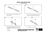
DV STOVE HORIZONTAL FLUE KIT (# 946-112) INSTALLATION
Minimum Installation Height:
F39: 59-3/4" ( 1518mm)
Review the following sequence of instructions
which are typical of most installations. The
sequence may vary depending on wall thick-
ness. Refer to fl ue location, see "Exterior
Flue Termination Location" section. and
clearance dimensions, see to "Clearances
to Combustibles" section.
1) Set the unit in its desired location. Check
to determine if wall studs will be in the way
of the fl uing system, adjust location until
all clearances are met and there are no
obstructions.
Note: A 1-1/2"(38mm) clearance around
the outer pipe must be maintained
except that only a 1" (25mm) clear-
ance is needed at the termination
end.
IMPORTANT:
Do not locate termination hood where
excessive snow or ice buildup may occur.
Be sure to check fl ue termination area after
snow falls, and clear to prevent accidental
blockage of fl uing system. When using
snow blowers, make sure snow is not directed
towards fl ue termination area.
2) Assemble a trial fi t to determine the verti-
cal center-line for the fl ue termination.
a) Cut a 241mm round hole on both the
interior and exterior wall.
b) Attach the 2 ft. pipe section to the fl ue
terminal and slide into position from
the exterior. The larger diameter end
of the adjustable pipe goes to the
fl ue terminal.
c) Install the 90
o
elbow onto the adjust-
able pipe to determine the vertical
centerline of the starter collar on the
unit.
Note: if the centerline cannot be
met, the adjustable sections will
have to be cut.
d) Cut the 2 ft. section of rigid pipe to
length. Ensure that the pipe length
DV STOVE HORIZONTAL FLUE KIT
Horizontal Stove Flue Kit (Part # 946-112) includes all the parts needed to install the F39 Freestand-
ing Gas unit with minimum horizontal and vertical vent dimensions. For installations that require
longer vertical and/or horizontal vents use the Dura-Vent system as shown in your manual.
Qty. Description
1) 2 Rigid Pipe Section 1.2m length, 165mm inside diameter
2) 1 Flex Liner, compressed aluminium 2 ply liner, 102mm inside diameter
3) 4 spring spacers
4) 1 90 deg. Elbow
5) 1 Decorative Wall Trim
6) 1 Adapter
7) 1 AstroCap Termination Cap
8) 2 Trim Collar
9) 1 tube of Mill-Pac, high temperature sealant
10) 12 Screws, #8 x 1/2" Self tapping, Stainless Steel
11) 14 Screws, #8 x 1/2" Self tapping, Black
12) 4 Screws #8 x 1-1/2" Drill Point, Stainless Steel
Optional:
946-206 Vinyl Siding Standoff
for AstroCap
Note:
a) Liner sections should be continuous
without any joints or seams.
b) This is an approved system, therefore
components in this system must not be
substituted for any other manufacturer's
products.
c) Wall Thimble is required when installing
through a combustible wall.

Regency
®
F39 Room Sealed Freestanding Gas Stove
11
INSTALLATION
when cut will seat onto both the starter
collar and the 90
o
elbow. Crimped
section of rigid pipe seats into the
90
o
elbow. Only cut the uncrimped
side of pipe.
Dismantle all pipe sections including fl ue
terminal.
3) Attach the 4" dia. fl ex liner to the fl ue terminal
ensuring that the fl ex overlaps the collar of
the fl ue terminal by a minimum of
1-3/8"(35mm). Use Mill-Pac to seal and
secure with 3 of the #8 x 1/2" screws (stain-
less steel).
4) Attach the 2 ft. pipe section to the fl ue termi-
nal using Mill-Pac and/or high temperature
silicone and attach with 3 of the #8 x 1/2"
screws (stainless steel).
6) A bead of non-hardening mastic should be
run around both the termination and vinyl
siding standoff to prevent water from entering
and to make a tight seal between the cap
and the standoff.
7) Stretch the 4" dia. fl ex liner out fully and get
a trial fi t of the liner onto the 4" dia. starter
collar.
8) Cut the 4" dia. fl ex liner to the desired
size.
Hint: leave an extra 12" to 16" of length, this
will make the fi nal assembly easier to work
with.
9) Secure the 4" dia. fl ex liner to the 4" adapter
with Mill-Pac and 3 of the #8 x 1/2" screws
(stainless steel).
10) Slide the Decorative Wall Cover over the
pipe sections.
11) Slide the 90
o
elbow (crimp end up) and the
2 ft. pipe section (crimp end up) over the
4" dia. fl ex liner.
12) Slide the trim collar over the pipe section to
cover the joint.
13) Install the spring spacers onto the pipe sec-
tions.
14) Secure the 4" dia. fl ex liner with adapter
onto the stove collar. Put a bead of Mill-Pac
around the appliance adapter and secure
with 3 screws (#8 x 1/2, stainless steel).
15) Attach the pipe section onto the starter
collar by sealing with Mill-Pac and/or high
temperature silicone and securing with 3 of
the #8 x 1/2" (black) screws. Pipe seams
should be facing the wall.
16) Attach the 90
o
elbow onto the pipe section by
sealing with Mill-Pac and/or high tempera-
ture silicone and securing with 3 of the #8
x 1/2" screws (black).
17) Slide the 2 ft. pipe section onto the 90
o
el-
bow. The fl ex may have to be compressed
back in order for the pipe to properly mate
to the elbow. Seal with Mill-Pac and/or high
temperature silicone and secure with 3 of
the #8 x 1/2" screws (black). Pipe seams
facing down.
18) Install the trim collar over the starter collar
and secure with a #8 x 1/2" screw (black).
If the pipe needs to be touched up, use only
Stove Brite High Temperature Metallic Black
Stove Paint.
NOTE: All inner joints must be sealed with
Mill-Pac.
All outer joints may be sealed with
high temperature silicone.
Note: The pipe seam should be facing
down.
Note: To make the installa-
tion more aestheti-
cally pleasing, we
recommend framing
out a square that the
cap can be mounted
on.
Note: If installing termination on a siding
covered wall, a vinyl siding standoff
or furring strips must be used to
ensure that the termination is not
recessed into the siding. For vinyl
siding standoff installation refer to
the Dura-Flue Termination instruc-
tions.
5) Slide the partially connected pipe and fl ue
terminal assembly through the wall (from
the exterior into the interior) and secure the
cap to the exterior wall with 4 of the supplied
screws (#8 x 1-1/2" drill point, stainless
steel).
Note: The four screws provided for the
fl ue cap should be replaced with ap-
propriate fasteners for stucco, brick,
concrete, or other types of sidings.
Hint: Apply the
sealant (Mill-
Pac and/or high
temperature
silicone) to the
outer pipe be-
fore connecting
the inner pipe.
#8 x ½" (13mm) Self Tapping, Stainless Steel
#8 x ½" Self Tapping, Black(13mm)
#8 x 1½" (38mm) Drill Point, Stainless Steel

12
Regency
®
F39 Room Sealed Freestanding Gas Stove
Pipe Length
Round Support
Box/Wall Thimble
(Part # 940)
Round
Support Box/
Wall Thimble
(Part # 940)
Vertical
Terminal
Storm Collar
Part # 953
Flashing
943 or 943S
Ceiling Firestop
(Part # 963)
24" (610mm)
Pipe Length
Adj.Pipe Length
11" - 14-5/8"
(279mm - 372mm)
90 Elbow
o
Wall Thimble
Part # 942
Vinyl Siding
Standoff (Optional)
Part #950
AstroCap
Termination Cap
(Part# 946-523)
DURA-FLUE
TERMINATION KIT
Planning Your Dura-Flue
Installation
There are two basic types of Dura-Flue Room
Sealed System installations: horizontal termi-
nation and vertical termination. Confi rm the
maximum horizontal run and maximum vertical
rise from the diagrams, refer to "Fluing Arrange-
ments" section.
When planning your installation, it will be nec-
essary to select the proper length of fl ue pipe
for your particular requirements. For horizontal
installations, determine the minimum clearance
from the rear of the unit to the wall. It is also
important to note the wall thickness. (The wall
thimble is suitable for 2 x 4 or 2 x 6 wall construc-
tion.) Select the amount of vertical rise desired
for "vertical-to-horizontal" type installations.
Warning: Always maintain required clear-
ances (air spaces) to nearby combustibles
to prevent a fi re hazard. Do not fi ll air spaces
with insulation.
The minimum clearance requirements between
the outer wall of the fl ue pipe and nearby com-
bustible surfaces is 1-1/4 inch. Be sure to check
the fl ue termination clearance requirements
from decks, windows, soffi ts, gas regulators, air
supply inlets and public walkways as specifi ed
in the Exterior Flue Terminal Locations on page
8 and in your local building codes.
To determine the length of fl ue pipe required
for vertical installations, measure the distance
from the unit fl ue outlet to the ceiling, the ceiling
thickness, the vertical rise in an attic or second
storey, and allow for suffi cient vertical height
above the roof line.
For multi-storey applications, fi re stops are
required at each fl oor level. If an offset is
needed, additional pipe, elbows and supports
will be required.
Do not exceed the maximum number of elbows.
One 90
o
for horizontal terminations and two 45
o
for vertical termination.
DURA-FLUE FLUING
COMPONENTS
You will require the following components with
your new Regency
®
Room Sealed Freestand-
ing Gas Stove. Please review your product to
make sure you have everything you need. In
the efl ue that you are missing any part, contact
your dealer.
Note: These are the minimum pieces re-
quired. Other parts may be required
for your particular installation. See
page 12 for a list of fl ue parts.
If installing termination on a siding covered wall,
a vinyl siding standoff or furring strips can be
used in order to ensure that the termination is
not recessed into siding.
The vinyl siding standoff is required for walls
with vinyl siding.
Minimum components for a Dura-Flue
Horizontal
Installation:
A) Dura-Flue Horizontal Termination Kit
B) Wall Thimble (required for combus-
tible walls)
Minimum components for a Dura-Flue Verti-
cal Termination:
C) Dura-Flue Vertical Termination Kit
See page 12 for pipe lengths.
The Simpson Dura-Flue Room Sealed System
offers a complete line of component parts for
installation of both horizontal and vertical installa-
tion. Many items are offered in decorative black,
as well as galvanized fi nish. The galvanized pipe
INSTALLATION
and fi ttings are used for concealed locations
such as attics or where corrosion is a factor,
such as above the roof line. Decorative brass
trim kits are available for both wall thimbles and
ceiling support boxes.
Part # Description
971 Horiz. Termination Kit includes:
90
o
black elbow, wall thimble cover,
horiz. square termination cap,
24"
black pipe, 11" -14" 5/8" adjust-
able
black pipe
970 Basic Horiz. Termination Kit
includes: 90
o
black elbow, wall
thimble cover, horiz. square
termination cap
978 Vert. Termination Kit includes
0/12 - 6/12 pitch adjustable
fl ashing, storm collar, low profi le
term. cap
908B 6" Pipe Length-Black
907B 9" Pipe Length-Black
906 12" Pipe Length Galv.
906B 12" Pipe Length-Black
904 24" Pipe Length Galv.
904B 24" Pipe Length-Black
903 36" Pipe Length Galv.
903B 36" Pipe Length-Black
902 48" Pipe Length Galv.
902B 48" Pipe Length-Black
911B 11"-14 5/8" Adj. Pipe Length-
Black
917B 17"- 24" Adj. Pipe Length Black
945 45
O
Elbow Galv.
Dura-Flue Basic
Horizontal Kit # 970
1 90
o
Elbow
1 Wall Thimble Cover
1 Astro Cap

Regency
®
F39 Room Sealed Freestanding Gas Stove
13
Diagram 5
Note: If installing termination on a siding
covered wall, a vinyl siding standoff or fur-
ring strips must be used to ensure that the
termination is not recessed into the siding.
The four wood screws provided should be
replaced with appropriate fasteners for
stucco, brick, concrete, or other types of
sidings.
5) Before connecting the horizontal run of fl ue
pipe to the fl ue termination, slide the black
decorative wall thimble cover over the fl ue
pipe, then slide the Wall Thimble (Part #
942) over the fl ue pipe.
6) Slide the appliance and fl ue assembly
towards the wall carefully inserting the fl ue
pipe into the fl ue cap assembly. It is impor-
tant that the fl ue pipe extends into the fl ue
cap a suffi cient distance so as to result in
a minimum pipe overlap of 1-1/4 inches.
Secure the connection between the fl ue
pipe and the fl ue cap using sheet metal
screws provided. See diagram 6.
7) Install the Wall Thimble in the center of the
10" square and attach with wood screws.
F39: 59-3/4" (1518mm)
Diagram 2
b) The location of the horizontal fl ue termi-
nation on an exterior wall must meet all
local and national building codes, and
must not be blocked or obstructed. For
External Flue Terminal Locations dia-
gram, refer to "Exterior Flue Termination
Location" section.
4) If installing the fl ue termination to a wall with
vinyl siding, the Vinyl Siding Standoff must
be used. Attach the Vinyl Siding Standoff to
the Horizontal Flue Termination, but fi rst run
a bead of non-hardening mastic around its
outside edges, so as to make a seal between
fl ue cap and the standoff. Install the Vinyl
Siding Standoff (Part # 950) between the
fl ue cap and the exterior wall and attach
with the four wood screws provided. Seal
around the Vinyl Siding Standoff on all four
sides. Diagram 5. The arrow on the fl ue
cap should be pointing up. Insure that the
1-1/4" clearances to combustible materials
are maintained. See diagram 5.
horizontal pipe, as shown in diagram 2.
Cut and frame the 10 inch square hole
in the exterior wall where the fl ue will be
terminated. If the wall being penetrated is
constructed of non-combustible material,
i.e. masonry block or concrete, a 7" diameter
hole is acceptable.
Note:
a) The horizontal run of fl ue should have a 1/4
inch rise for every 1 foot of run towards
the termination. Never allow the fl ue to
run downward. This could cause high
temperatures and may present the
possibility of a fi re.
INSTALLATION
DURA-FLUE
HORIZONTAL
INSTALLATIONS
1) Set the unit in its desired location. Check to
determine if wall studs or roof rafters are in
the way when the fl uing system is attached.
If this is the case, you may want to adjust
the location of the unit.
2) Room Sealed pipe and fi ttings are designed
with special twist-lock connections to con-
nect the fl uing system to the appliance fl ue
outlet. A twist-lock appliance adaptor is
installed on the unit at the factory. Assemble
the desired combination of
pipe and elbows to the ap-
pliance adaptor with
pipe seams oriented
towards the wall or
ceiling, as much out of
view as possible. The
fi nal positioning of the
pipe and 90
o
elbow as-
sembly is determined
by the mounting
orientation of the
adaptor on the
stove and twist-
locked for a solid
connection.
Note:
a) Twist-lock procedure: Four indentations,
located on the female ends of pipes and
fi ttings, are designed to slide straight
onto the male ends of adjacent pipes
and fi ttings, by orienting the four pipe
indentations so they match and slide in
to the four entry slots on the male ends
Diagram 1
945B 45
O
Elbow-Black
945G 45
O
Elbow-Swivel Galv.
945BG 45
O
Elbow-Swivel-Black
990 90
O
Elbow Galv.
990B 90
O
Elbow-Black
990G 90
O
Elbow-Swivel Galv.
990BG 90
O
Elbow-Swivel-Black
991 High Wind Term. Cap (Vertical)
980 Vertical Term. Cap
982 Snorkel-14" Rise Term.Cap
981 Snorkel-36" Rise Term.Cap
940 Wall Thimble-Support/Box
941 Cathedral/Ceiling-Support/Box
3951 Brass Trim-Wall Thimble/
Ceiling Support
963 Firestop Spacer
943 Flashing 0/12-6/12
943S Flashing 7/12-12/12
953 Storm Collar
950 Vinyl Siding Standoff
988 Wall Strap
942 Wall Thimble
Parts not supplied by Dura-Flue
946-506/P Flue Guard (Optional)
(diagram 1). Push the pipe sections
completely together, then twist-lock
one section clockwise approximately
one-quarter turn, until the two sections
are fully locked. The female locking lugs
will not be visible from the outside on
the Black Pipe or fi ttings. They may be
located by examining the inside of the
female ends. Apply sealant "Mill-Pac" to
inner pipe and high temp silicone sealant
to outer pipe on every twist-lock joint.
Hint: Apply silicone to female end.
b) Horizontal runs of fl ue must be supported
every three feet. Wall straps are available
for this purpose.
3) With the pipe attached to the stove, slide
the stove into its correct location, and mark
the wall for a 10" x 10" (inside dimensions)
square hole. The center of the square hole
should line up with the centerline of the

14
Regency
®
F39 Room Sealed Freestanding Gas Stove
Diagram 11: The upper half of the fl ashing is
installed under the roofi ng material and not
nailed down until the chimney is installed. This
allows for small adjustments.
4) Assemble the desired lengths of black pipe
and elbows necessary to reach from the
appliance adaptor up though the Round
Support Box. Insure that all pipes and elbow
connections are in the fully twist-locked
position and sealed.
5) Cut a hole in the roof centred on the small
drilled hole placed in the roof in Step 2. The
hole should be of suffi cient size to meet
the minimum requirements for clearance
to combustibles of 1-1/4". Slip the fl ashing
under the shingles (shingles should overlap
half the fl ashing) as per diagram 11.
Diagram 12
7) Ensure fl ue is vertical and secure the base
of the fl ashing to the roof with roofi ng rails,
slide storm collar over the pipe section and
seal with a mastic.
8) Install the vertical termination cap by twist
locking it.
Notes:
a) For multistorey vertical installations, a
Ceiling Fire stop (Part # 963) is required
at the second fl oor, and any subsequent
fl oor. Diagram 13. The opening should
be framed to 10 " x 10" inside dimen-
6) Continue to assemble pipe lengths.
Note: If an offset is necessary in the attic to
avoid obstructions, it is important to
support the fl ue pipe every 3 feet, to
avoid excessive stress on the elbows,
and possible separation. Wall straps
are available for this purpose. See
diagram 7.
Galvanized pipe and elbows may be utilized
in the attic as well as above the roofl ine.
The galvanized fi nish is desirable above the
roofl ine due to its higher corrosion resist-
ance.
Continue to add pipe sections through the
fl ashing until the height of the fl ue cap meets
the minimum height requirements specifi ed
in diagram 12 or local codes. Note that for
steep roof pitches, the vertical height must
be increased. A poor draft, or down drafting
can result from high wind conditions near
big trees or adjoining roof lines, in these
cases, increasing the fl ue height may solve
the problem.
Roof Pitch Minimum Flue Height
Feet Meters
fl at to 7/12 2
0.61
over 7/12 to 8/12 2 0.61
over 8/12 to 9/12 2 0.61
over 9/12 to 10/12 2.5 0.76
over 10/12 to 11/12 3.25 0.99
over 11/12 to 12/12 4 1.22
over 12/12 to 14/12 5 1.52
over 14/12 to 16/12 6 1.83
over 16/12 to 18/12 7 2.13
over 18/12 to 20/12 7.5 2.29
Diagram 10
Diagram 9
Diagram 8
Diagram 7
Diagram 6
DURA-FLUE VERTICAL
TERMINATION
1) Maintain the 1-1/4" clearances
(air spaces) to combustibles
when passing through ceil-
ings, walls, roofs, enclo-
sures, attic rafter, or other
nearby combustible surfaces.
Do not pack air spaces with
insulation. Check page 9 for
the maximum vertical rise
of the fl uing system and the
maximum horizontal offset
limitations.
3) To install the Round Support Box/Wall Thim-
ble in a fl at ceiling, cut a 10 inch square hole
in the ceiling centred on the hole drilled in
Step 2. Frame the hole as shown in diagram
10.
INSTALLATION
8) Slide the decorative wall thimble up to the
wall surface being careful not to scratch
the paint and attach with screws provided.
Apply decorative brass or chrome trim if
desired. See diagram 7.
2) Set the gas appliance in
its desired location. Drop a
plumb bob down from the
ceiling to the position of the
appliance fl ue exit, and
mark the location where
the fl ue will penetrate the
ceiling. Drill a small hole
at his point. Next, drop a
plumb bob from the roof to
the hole previously drilled
in the ceiling, and mark the
spot where the fl ue will penetrate the roof.
Determine if ceiling joists, roof rafters or
other framing will obstruct the fl uing system.
You may wish to relocate the appliance or
to offset, as shown in diagram 9 to avoid
cutting load bearing members.

Regency
®
F39 Room Sealed Freestanding Gas Stove
15
GAS CONNECTION
The gas connection is a 3/8" NPT 90
o
elbow.
The gas line can be rigid pipe or to make in-
stallation easier, use a listed fl exible connector
and/or copper tubing if allowed by local codes.
Since some municipalities have additional
local codes it is always best to consult with
your local authorities and the CAN/CGA B149
installation codes.
When using copper or fl ex connectors use only
approved fi ttings. Always provide a union so
that gas lines can be easily disconnected for
burner and/or valve servicing. Flare nuts for
copper lines and fl ex connectors are usually
considered to meet this requirement.
Important: Always check for gas leaks with a
soap and water solution or gas leak detector.
Do not use open fl ame for leak testing.
Note: Prior to any pressure testing of
the gas supply piping system that
exceeds test pressures of 3.45 kPa,
this appliance must be disconnected
from the piping system. If test pres-
sures equal to or less than 3.45 kPa
are used then this appliance must be
isolated from the piping system by
closing its individual manual shut-off
valve during the testing.
GAS PIPE PRESSURE
TESTING
The appliance must be isolated from the gas sup-
ply piping system by closing its individual manual
shut-off valve during any pressure testing of the
gas supply piping system at test pressures equal
to or less than 3.45 kPa. Disconnect piping from
valve at pressures over 3.45 kPa.
The manifold pressure is controlled by a regu-
lator built into the gas control, and should be
checked at the pressure test point.
INSTALLATION
Offset Chart
Diagram 13
sions, in the same manner as shown in
diagram 10.
b) Any occupied areas above the fi rst fl oor,
including closets and storage spaces,
through which the vertical fl ue passes, must
be enclosed.
CATHEDRAL CEILINGS
Round Support (RDS) &
Square Support (SQS)
If your home has a cathedral ceiling (no attic
space between the ceiling and the roof), install
the chimney and support as follows.
Slope "X"
0/12 - 2/12 4"
2/12 - 7/12 5-1/2"
7/12 - 12/12 6-3/4"
12/12 - 24/12 7-1/2"
24/12+ 12-1/2"
1) Situate the chimney in a convenient loca-
tion as near as possible to the appliance
outlet. Cut and frame a hole in the roof for
the support. The sides of this hole must be
vertical with 1 1/4" clearance.
2) Place the support in the opening. Lower it
to the correct height as determined by the
table and diagram below.
Using a level, make sure the support is
vertical. If the support extends above the
roof, cut it fl ush with the top of the roof.
Nail the support to the frame opening using
(8) 3" spiral nails or #8 x 1-1/2" screws.
Note: If you are using a 6" square support
you may fi nd it diffi cult to screw it
in place because it is fairly small
inside.
Simpson Dura-Flue has provided angle
brackets with this support which can be
screwed to the outside of the support
box and nailed to surrounding framing as
required. Use a minimum of four #8 x 1/2"
screws per bracket. In some cases these
brackets may need to be trimmed (e.g.:
to fi t under a fl ashing). Place the Finish
Collar around the support and fasten it to
the ceiling using the screws provided.
3) Use appropriate roof fl ashing. Place the
fl ashing under the upper shingles and on
top of the lower shingles approximately
half of the fl ashing should be under the
shingles.
4) Assemble the desired lengths of Black Pipe
and Elbows necessary to reach from the
appliance adaptor up through the support
box and fl ashing to proper height as per
Dia. 12, local codes or page 9. Ensure
that all pipe and elbow connections are in
their fully twist lock position.
5) Ensure fl ue is vertical and secure fl ashing
to the roof with roofi ng nails. Slide the
storm collar over the pipe section and seal
with a mastic.
6) Twist lock the fl ue cap on to the last sec-
tion.
Support Extensions - Round
(RDSE) or Square (SQSE)
Steep pitched cathedral ceilings may require
the use of a support extension. This piece fi ts
down inside the support and can be adjusted to
increase the support's length by up to 22". The
extension is attached to the support using the
eight metal screws provided. Be sure there is
at least a 2 inch overlap where the extension
joins the support.

16
Regency
®
F39 Room Sealed Freestanding Gas Stove
Burner Inlet Orifi ce Sizes:
NG LPG
Burner #32 #50
2.95mm 1.78mm
Max. Input NG 40 Mj/h
LPG 38 Mj/h
Min. Input NG 20 Mj/h
LPG 19 Mj/h
Supply Pressure
NG min. 1.13 kPa
LPG min. 2.75 kPa
Manifold Pressure
NG .94 kPa
LPG 2.55kPa
Electrical: 240 V. 1.13A 60Hz.
Circulation: 2 speed fan, 125/75 CFM.
Log Set: Ceramic fi ber, 7 per set.
System Data
F39 Converted to 31mj
Burner Inlet Orifi ce Sizes:
NG #37 2.65mm
LPG #52 1.6mm
Max. Input - NG/LPG
31 Mj/h
Min. Input - NG/LPG
16 Mj/h
Supply Pressure
NG min. 1.13 kPa
LPG min. 2.75 kPa
Manifold Pressure
NG .89 kPa
LPG 2.55kPa
Electrical: 240 V. 1.13A 60Hz.
Circulation: Variable speed fan, 125/75
CFM.
Log Set: Ceramic fi ber, 7 per set.
System Data
F39 with 40mj
INSTALLATION
Note: To properly check gas pressure, both
inlet and manifold pressures should
be checked using the valve pressure
ports on the valve.
1) Make sure the valve is in the "OFF" posi-
tion.
2) Loosen the "IN" and/or "OUT" pressure
tap(s), turning counterclockwise with a 1/8"
wide fl at screwdriver.
3) Attach manometer to "IN" and/or "OUT"
pressure tap(s) using a 5/16" ID hose.
4) Light the pilot and turn the valve to "ON"
position. Read manometer.
5) The pressure check should be carried out
with the unit burning and the setting should
be within the limits specifi ed on the safety
label.
6) When fi nished reading manometer, turn
off the gas valve, disconnect the hose and
tighten the screw (clockwise) with a 1/8" fl at
screwdriver. Note: Screw should be snug,
but do not over tighten
Valve Description
1) Gas on/off knob
2) Manual high/low adjustment
3) Pilot Adjustment
4) Thermocouple Connection
5) Main Operator
6) Outlet Pressure Tap (Manifold
Pressure)
7) Inlet Pressure Tap (Supply
Pressure)
8) Pilot Outlet
9) Main Gas Outlet
10) Flange Securing Screw Holes
11) Alternative TC Connection Point
12) Thermoelectric Unit
13) Additional Valve Mounting Hole
AERATION
ADJUSTMENT
The burner aeration is factory set but may need
adjusting due to either the local gas supply or
altitude.
F39 with 40mj
F39-NG NG: Full open
F39-LPG LPG: Full open
F39 with 31mj
F39-NG NG 6mm open
F39-LPG LPG 10mm open
Note: Any damage due to carboning resulting
from improperly setting the aeration
controls is NOT covered under war-
ranty.

Regency
®
F39 Room Sealed Freestanding Gas Stove
17
INSTALLATION
CONVERSION KIT #731-968 FROM NG TO LPG
THIS CONVERSION MUST BE DONE BY AN AUTHORIZED GAS FITTER IF IN DOUBT DO NOT DO THIS CONVERSION !!
WARNING!
Do not over tighten the screw.
Recommended to
grip the wrench by the short side.
1) Shut off the gas supply.
2) Remove the louvers (and bay door if it is
installed).
3) Open the fl ush door and remove the
door.
4) Remove the logs and embers (if used).
5) Remove the 2 screws holding the Burner
Assembly to the fi rebox base. Push the
Burner Assembly to the left and lift out.
Remove the 2 screws, push Burner
Assembly to the left and lift out.
7) Unscrew the pilot orifi ce with the allen key;
then replace with the LPG pilot orifi ce and
the pilot cap, provided in the kit.
8) Remove burner orifi ce with a 1/2" wrench.
Use another wrench to hold on to the elbow
behind the orifi ce. Discard orifi ce.
Burner Orifi ce
9) Reinstall new burner orifi ce LPG stamped
#52 and tighten.
10) Turn control knob to the “OFF” position.
Fi
g
.1
11) Remove the black
protection cap by hand
from the hi-low knob
(Fig.1).
Fi
g
.2
14) Flip the screw (Fig. 3).
Fig.4
Fig.3
15) Using the Allen wrench
as shown in Fig.4,
rotate the screw clock-
wise until snug, do not
overtighten.
12) Insert a 5/32” or 4mm
Allen wrench into the
hexagonal key-way of
the screw (Fig. 2), rotate
it counter-clockwise until
it is free and extract it.
13) Check that the screw is clean and if
necessary remove dirt.
Conversion Kit Contains:
Qty. Part # Description
1 904-390 Burner Orifi ce #52
1 904-529 5/32" Allen Key
1 918-590 Label "Converted
to LPG"
1 908-528 Red "LPG" label
1 910-037 LPG Injector
(Pilot Orifi ce)
1 918-484 Instruction Sheet
6) Pull off the pilot cap to expose the pilot
orifi ce.
16) Verify that if the conversion is from NG to
LPG, the screw must be re-assembled with
the red o-ring visible (Fig. 5).
LPG Configuration
Red o-ring visible
Fig.5
17) Re-assemble the black protection cap
(Fig. 6).
Fig. 6
WARNING!
Also check that the pilot and main
burner injectors are appropriate for
the gas type.
19) Attach the label "This unit has been
converted to LPG" near or on the serial
# decal.
20) Replace yellow "NG" label with red "LPG"
label.
21) Check for gas leaks.
22) Check inlet and outlet pressures.
23) Check operation of fl ame control.
24) Check for proper fl ame appearance and
glow on logs.
18) Reverse step 2).

18
Regency
®
F39 Room Sealed Freestanding Gas Stove
LOG SET
INSTALLATION
Read the instructions below carefully and
refer to the diagrams. If logs are broken
do not use the unit until they are replaced.
Broken logs can interfere with the pilot
operation.
The gas log kit contains the following:
a) 02-65 Rear Log
b) 02-56 Middle Left Log
c) 02-44 Front Left Log
d) 02-46 Left Top Log
e) 02-45 Front Right Log
f) 02-47 Center Log
g) 02-48 Middle Right Log
h) Embers 902-151
i) Lava 902-154
Note: Install Optional Brick Panels prior to
installing logs.
Embers Embers
The "02" refer numbers (i.e. 02-65) are
molded into the rear of each log.
1) Carefully remove the logs from the box and
unwrap them. The logs are fragile, handle
with care - do not force into position.
2) Sprinkle the embers on the left and right
sides of the fi rebox base.
INSTALLATION
CONVERSION TO LOWER BTU RATING
THIS CONVERSION MUST BE DONE BY AN AUTHORIZED GAS
FITTER IF IN DOUBT DO NOT DO THIS CONVERSION !!
NG Conversion Kit 730-920
Contains:
Qty. Part # Description
1 904-240 Burner Orifi ce #37 (NG)
1 918-034 Decal "Converted to 30,000 Btu"
1 918-033 Instruction Sheet
LPG Conversion Kit 730-922
Contains:
Qty. Part # Description
1 904-390 Burner Orifi ce #52 (LPG)
1 918-034 Decal "Converted to 30,000 Btu"
1 918-033 Instruction Sheet
Additional Piece (pkg. with unit:
1 Log Bracket Restrictor
1) Shut off the gas supply.
2) Open the front door. Carefully remove the
logs and lava rock.
3) Remove burner. See diagram below.
Burner Orifi ce
4) Unscrew the 2 Rear
Log Pins and move
to the front hole posi-
tion.
5) Remove Rear Log
Bracket and slide the
Log Bracket Restric-
tor between the Rear
Position the Log Bracket Restrictor between
the Rear Log Bracket and the burner.
6) Remove burner orifi ce with a 1/2" spanner
and discard.
7) Reinstall new burner orifi ce (NG stamped
#37 or LPG stamped #52) and tighten.
8) Reverse steps 3) and 2).
9) Adjust Flue restrictor setting: To set the Flue
restriction as indicated in the diagram, simply
loosen the screws and push the fl ue restric-
tor plate to the correct position. Tighten the
screws.
Unit Btu/h Restrictor Opening
F39 40 Mj/h A 45mm
31 Mj/h B 35mm
Note: Use a magnetic
type screwdriver if
possible.
Log Bracket and the burner, secure with the
2 screws.
Flue Restrictor set-
ting at High Btu/h
Flue Restrictor set-
ting at Low Btu/h
10) Attach the label "This unit has been con-
verted to..." on top of the data badge over
the higher Btu information.
11) Check for gas leaks.
12) Check inlet and outlet pressures.
13) Check operation of fl ame control. Check for
proper fl ame appearance on logs.

Regency
®
F39 Room Sealed Freestanding Gas Stove
19
Notch
E)02-45
Bracket
A)02-65
The bottom right edge of Log G)02-48 must
sit snugly against the bracket
Side View
G)02-48
E)02-45
F)02-47
11) Position notch in Front Right Log G)02-48
on Log F)02-47 and push the bottom right
edge against the bracket on the burner
tray.
G)02-48
12) Test fi re to ensure proper light off (make
sure fl ame fl ows smoothly from one end
of burner to the other. If there is any fl ame
hesitation, check that area for any blockage
of the burner port.
F)02-47
E)02-45
A)02-65
G)02-48
D)0
2-46
B)02-56
C)02-44
Cutout
Pin
D)02-46
B)02-56
A)02-65
7) Place the Left Top Log D)02-46 on the pin
on Log B)02-56 and on top of the cutout
on Log A)02-65.
E)02-45
C)02-44
8) Place Front Right Log E)02-45 on the two
pins as shown.
9) Place the lava rock in the area between
the left and right logs, leaving a space in
the middle for log (F) 02-47.
CutoutNotch
F)02-47
E)02-45
A)02-65
10) Place the notch in Center Log F)02-47 over
Log E)02-45 and across the cutout on Log
A)02-65.
C)02-44
Pins on Rear Log Support
A)02-65
B)02-56
3) Place Rear Log A)02-65 on the two pins on
the rear log support.
4) Place the Middle Left Log B)02-56 on the
two pins as shown.
5) Sprinkle some lava rock just in front of B)
02-56 on the burner holes.
lava rock
B)02-56
6) Place Front Left Log C)02-44 onto the 2
front pins as shown.
INSTALLATION

20
Regency
®
F39 Room Sealed Freestanding Gas Stove
OPTIONAL
WALL THERMOSTAT
A wall thermostat may be installed if desired.
Connect the wires as per the wiring diagrams.
Note that the wires are connected to the "TH"
on the gas valve. Use table below to determine
the maximum wire length:
Note: Preferable if the thermostat is installed
on an interior wall.
Regency
®
offers an optional programmable
thermostat but any 250-750 millivolt rated non-
anticipator type thermostat that is CSA, ULC or
UL approved may be used.
OPTIONAL REMOTE
CONTROL
Use the Regency
®
Remote Control Kit approved
for this unit. Use of other systems may void
your warranty.
The remote control kit comes with a hand held
transmitter, a receiver and a wall mounting
plate.
1) Choose a convenient location on the wall
to install the receiver and the receptacle
box (protection from extreme heat is very
important). Run wires from the fi replace to
that location, use Thermostat Wire Table.
2) Connect the wires as per the wiring diagram
above.
CAUTION
Do not connect the millivolt
wall thermostat wires
to the 240V wires.
14 GA.
16 GA.
18 GA.
20 GA.
22 GA.
15.24 m
9.75 m
6.10 m
3.66 m
2.71 m
Recommended Maximum Lead Length
(Two-Wire) When Using Wall
Thermostat (CP-2 System)
Wire Size Max. Length
Thermostat Wire Table
INSTALLATION
Diagram 1
FRONT DOOR
INSTALLATION
(packaged separately)
1) Open the two side panels.
2) Slide the door
onto the two hinge
pins making sure
the two pieces
are fl ush togeth- er.
See diagram 1.
4) The latches should already be at the proper
setting. If they are too hard or too easy
to close, you may want to adjust them by
loosening the latch catch. See diagram 3.
Diagram 2
Diagram 3
5) Remove the blue plastic protective coating
from the glass.
6) Test the seal around the door by placing
a piece of paper between the unit and the
door, close the door and try to pull the paper
out. If it slips out easily, then the door is not
properly sealed. Tighten or loosen the latch.
See diagram 3.
3) Close the door.
The latch plate
must be cen-
tered around the align-
ment pin. See diagram
2. If the latch plate
interferes with the cor-
ner of the stove you
may want to angle the
plate slightly so the door
closes easier.
Note: The door latch may require adjust-
ment as the door gasket material
compresses after a few fi res and
after glass replacement. Turn the
latch catch inward or outward to
loosen or tighten.
CAUTION
Do not connect the millivolt re-
mote control wires to
the 240V wires.
3) Install 3 AAA alkaline batteries in transmitter
and 4 AA alkaline batteries in the receiver.
Install the receiver and its cover in the wall.
Switch the remote receiver to "remote"
mode. The remote control is now ready for
operation.
FINAL CHECK
Before leaving this unit with the customer, the
installer must ensure that the appliance is fi ring
correctly. This includes:
1) Clocking the appliance to ensure the cor-
rect fi ring rate (rate noted on label) at 15
minutes.
2) If required, adjusting the primary air to ensure
that the fl ame does not carbon. First allow
the unit to burn for 15 min. to stabilize.
3) Check for proper draft.
CAUTION
Any alteration to the product that causes
sooting or carboning that results in damage
to the exterior facia is not the responsibility
of the manufacturer.
/