Page is loading ...

CLS-EXP-DIMFLV
0-10 V Fluorescent Dimmer Expansion Module
Installation Guide
Description
The Crestron
®
CLS-EXP-DIMFLV enables the expansion of iLux
®
Integrated Lighting
System (CLS-C6 Series) and other Crestron lighting dimmers to allow control of 0-10
volt uorescent dimming ballasts. It can also be used to switch nondimmable loads
including LED, incandescent, MLV, ELV, HID, uorescent ballasts, and motors. The
CLS-EXP-DIMFLV supports 120, 230, or 277 volt loads up to 16 amps.
Any output channel of the iLux system can be used to control the CLS-EXP-DIMFLV to
dim a fully loaded circuit. It is also compatible with CLW-series in-wall dimmers and select
CLX-series lighting control modules. The metal enclosure is designed for mounting to
a vertical surface and can be installed in an environmental air-handling space above a
suspended ceiling. Conduit knockouts are provided on the bottom and lower sides. All
connections are made via screw terminals behind the front cover.
NOTE: CLX-series lighting control modules are compatible only with forward-phase
dimming modules.
CLS-EXP-DIMFLV Specications
Specication Details
Load Ratings
Dimmer Channels
Lamp Load Rating
Motor Load Rating
Minimum Load
at 120 volts
at 230 volts
at 277 volts
Load Types
Dimmable Load
Switch Load
1
16 Amps @ 120 to 277 Volts;
0.5 HP @ 120 Volts, 1 HP @ 230/277 Volts
15 watts
25 watts
30 watts
0-10 Volt uorescent ballast or LED driver (4-wire)
LED, incandescent, uorescent, magnetic low voltage,
electronic low voltage, neon/cold cathode, high-intensity
discharge (HID), motors
Input Voltages
Line Power
Control Input
120–277 Vac, 50/60 Hz
120–230 Vac, 50/60 Hz, phase independent of line power
and load;
Presents a 25 watt load to the controlling device
Electrical Terminals
Captive screw type;
Accommodates two 22–12 AWG (0.34–4.0 mm
2
)
wires
Enclosure
Surface mount module with (2) integral mounting
anges, galvanized steel with gray matte powder
coat front panel, extruded aluminum heat sink,
(4) 1/2 in (13 mm) and 3/4 in (20 mm) conduit
knockouts provided on bottom and lower left and
right sides
Environmental
Temperature
Humidity
Heat Dissipation
32° to 104 °F (0° to 40 °C)
10% to 90% RH (noncondensing)
70 Btu/h at maximum load, 16amps
Dimensions
Height
Width
Depth
8.82 in (224 mm)
6.39 in (163 mm)
3.18 in (81 mm)
Weight 3.3 lbs (1.5 kg)
Maximum Expansion Modules per
Controller Output
5
Additional Resources
Visit the product page on the Crestron website (www.crestron.com)
for additional information and the latest rmware updates. Use a QR
reader application on your mobile device to scan the QR image.
Physical Description
This section provides information on the connections and indicators available on the
CLS-EXP-DIMFLV.
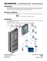
CLS-EXP-DIMFLV Overall Dimensions - Front View
8.82 in
(224 mm)
8.31 in
(212 mm)
Ø 0.19 in
(5 mm)
7.31 in
(186 mm)
0.50 in
(13 mm)
Ø 0.25 in
(7 mm)
5.79 in
(148 mm)
4.99 in
(127 mm)
CLS-EXP-DIMFLV Overall Dimensions - Side View
2.02 in
(53 mm)
1.56 in
(40 mm)
3.18 in
(81 mm)
3.07 in
(78 mm)
CLS-EXP-DIMFLV Overall Dimensions - Rear View
6.39 in
(163 mm)
1.64 in
(42 mm)
1.64 in
(42 mm)
CLS-EXP-DIMFLV Hardware Connections
OUTPUT
SW OUT: Switched load output
HOT: Line power input
NEUT: Neutral connection for line power input and
load
INPUT
CTRL: Control input from CLS(I)-C6 Series,
CLW-DIM Series, CLX(I)-DIM Series, GLX-DIM6,
GLXX-2DIM8, DIN-1DIM4, or DIN1-DIMU4
dimmers
NEUT: Neutral connection for control input
0-10V
+/-:
(2) Captive screw terminals,1 dimming control
output;
Class 1 or Class 2 wiring allowed;
Control voltage: 0-10 Vdc, 70 mA
Ground
(1) 3-terminal chassis ground bus
bar
Installation
Refer to the following diagram when installing a CLS-EXP-DIMFLV module.
NOTE: Install in accordance with all local and national electrical codes.
NOTE: To prevent potential heat damage to the drywall, do not mount the
CLS-EXP-DIMFLV directly onto drywall. Mount a piece of 1/2 in (13 mm) minimum thick
plywood between the CLS-EXP-DIMFLV and the drywall.
NOTE: To ensure proper ventilation, the device must be installed vertically on a vertical
surface. Install the device with 6 inches (153 mm) of clearance from the top and bottom
of the device.
Module Installation
Mounting surface
CLS-EXP-DIMFLV
#8 mounting screw
(not included)

Wiring
To wire the CLS-EXP-DIMFLV, remove the cover and make the connections.
WARNING: RISK OF SERIOUS PERSONAL INJURY. Turn off power at the circuit
breaker(s) prior to installation. Installing with the power on can result in serious personal
injury and damage to the device.
Remove the Cover
Use a #2 Phillips screwdriver to remove the cover screws and then the cover.
Remove Cover Screws
Cover
screws
Make the Connections
There are seven captive screw terminals on the CLS-EXP-DIMFLV that allow power input,
power output, and load control.
NOTE: Observe the following points:
• Strip wires to 7/16 in (12mm).
• Tighten terminal screws to 7 in-lbs (0.79Nm).
• Captive screw terminals accept up to two 22 to 12 AWG (0.34 to 4mm
2
) wires per
terminal.
• Dimmer channels controlling one or more CLS-EXP-DIMFLV modules must not be
wired to control any other type of load.
• While these diagrams show a CLS-C6 as the controlling source, other Crestron
products such as CLW-series wall dimmers (Cresnet
®
and inNET™ dimmers) and
CLX-series dimming modules can be used as well. Refer to “CLS-EXP-DIMFLV
Specications” on page 1 for details.
• Use a neutral wire for a CLW-Series wall dimmer.
• Use 75°C copper wire only.
• The CLS-EXP-DIMFLV presents a 25 W load to the controlling dimmer. A maximum
of ve CLS-EXP-DIMFLV modules may be connected to the controlling dimmer,
which cannot be wired to control any other loads besides the CLS-EXP-DIMFLV
modules.
• Separate Class 1 and Class 2 wires. When wiring a 0-10 V uorescent dimmer, the
+ and – make connections using Class1 or Class2 wiring. If Class 1 wiring is used,
the barrier between the NEUT and + terminals can be removed.
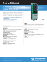
Wire the CLS-EXP-DIMFLV for a 0-10 V dimming or a switching application.
CLS-EXP-DIMFLV Wiring for 0-10 V Dimming
Neutral
CLS(I)-C6
LOAD 3
LOAD 2
LOAD 1
HOT
NEUTRAL
Neutral
Violet
Gray
Black
White
Hot
(120 to 230 Vac)
Hot
(120 to 277 Vac)
0-10 V uorescent
dimming ballast
CLS-EXP-DIMFLV Wiring for Switching Application
Neutral
CLS(I)-C6
LOAD 3
LOAD 2
LOAD 1
HOT
NEUTRAL
Neutral
Black
White
Hot
(120 to 230 Vac)
Hot
(120 to 277 Vac)
Switched load
After wiring is complete, replace the cover and the cover screws. Apply power to the line or
load and turn on the controlling device. The power indicator LED lights indicating that power
is supplied to the module.
Problem Solving
The following table provides corrective action for possible trouble situations. If further
assistance is required, please contact a Crestron customer service representative.
CLS-EXP-DIMFLV Troubleshooting
Trouble Possible Cause(s) Corrective Action
The load does not turn on. The controlling dimmer or
switch is not working.
Make sure that the
controller is powered on.
Make sure that a
compatible dimmer is being
used.
No power is applied to the
HOT terminal.
Check the circuit breaker.
Check that the green power
LED inside the unit is lit.
The load turns on and off
but does not dim.
The controlling unit is either
not a dimmer or has been
set to non-dim.
Verify that dimmer is
compatible with the
CLS-EXP-DIMFLV. Refer
to "CLS-EXP-DIMFLV
Specications" on page 1.
Verify that the controlling
channel has not been
programmed as non-dim.
The lights do not dim
properly.
An incompatible dimmer is
being used.
Make sure that the dimmer
is one of those listed
in "CLS-EXP-DIMFLV
Specications" on page 1.
This product is Listed to applicable UL
®
Standards and requirements tested by Underwriters
Laboratories Inc.
Ce produit est homologué selon les normes et les exigences UL applicables par Underwriters
Laboratories Inc.
Federal Communications Commission (FCC) Compliance Statement
This device complies with part 15 of the FCC Rules. Operation is subject to the following conditions:
(1) This device may not cause harmful interference and (2) this device must accept any interference
received, including interference that may cause undesired operation.
CAUTION: Changes or modications not expressly approved by the manufacturer responsible for
compliance could void the user’s authority to operate the equipment.
NOTE: This equipment has been tested and found to comply with the limits for a Class B digital device,
pursuant to part 15 of the FCC Rules. These limits are designed to provide reasonable protection against
harmful interference in a residential installation. This equipment generates, uses and can radiate radio
frequency energy and, if not installed and used in accordance with the instructions, may cause harmful
interference to radio communications. However, there is no guarantee that interference will not occur in
a particular installation. If this equipment does cause harmful interference to radio or television reception,
which can be determined by turning the equipment off and on, the user is encouraged to try to correct
the interference by one or more of the following measures:
• Reorient or relocate the receiving antenna.
• Increase the separation between the equipment and receiver.
• Connect the equipment into an outlet on a circuit different from that to which the receiver is
connected.
• Consult the dealer or an experienced radio/TV technician for help.
The product warranty can be found at www.crestron.com/warranty.
The specic patents that cover Crestron products are listed at patents.crestron.com.
Certain Crestron products contain open source software. For specic information, please visit
www.crestron.com/opensource.
Crestron, the Crestron logo, Cresnet, iLux, and inNET are either trademarks or registered trademarks
of Crestron Electronics, Inc. in the United States and/or other countries. Crestron and the Crestron logo
are either trademarks or registered trademarks of Crestron Electronics, Inc. in the United States and/
or other countries. UL and the UL logo are either trademarks or registered trademarks of Underwriters
Laboratories, Inc. in the United States and/or other countries. Other trademarks, registered trademarks,
and trade names may be used in this document to refer to either the entities claiming the marks and
names or their products. Crestron disclaims any proprietary interest in the marks and names of others.
Crestron is not responsible for errors in typography or photography.
This document was written by the Technical Publications department at Crestron.
©2017 Crestron Electronics, Inc.
Crestron Electronics, Inc. Installation Guide - DOC. 6680C
15 Volvo Drive Rockleigh, NJ 07647 (2020652)
Tel: 888.CRESTRON 07.17
Fax: 201.767.7576 Specications subject to
www.crestron.com change without notice.
/