Page is loading ...

GLPAC-DIMFLV
Introduction
The GLPAC-DIMFLV is a Crestron Green Light
®
integrated lighting system designed for use as a standalone
lighting controller in classrooms, conference rooms, and offices. While able to control four or eight channels of
dimmable fluorescent loads, each GLPAC-DIMFLV provides a link to a centralized Crestron
®
lighting control
system via Cresnet
®
for control and monitoring of the system. Add optional real-time power monitoring and
Crestron Fusion EM
®
Energy Management Software to help track and minimize energy usage throughout a facility.
The GLPAC-DIMFLV is available in the following models.
NOTE: The devices listed below are functionally identical. For simplicity within this guide, the term
“GLPAC-DIMFLV” is used except where noted.
Available GPPAC-DIMFLV Models
NAME DESCRIPTION
GLPAC-DIMFLV4 Green Light Integrated Lighting System, 4-Channel
GLPAC-DIMFLV4-CP Green Light Integrated Lighting System, 4-Channel with
Chicago Plenum Enclosure
GLPAC-DIMFLV4-PM Green Light Integrated Lighting System, 4-Channel with
Power Monitoring
GLPAC-DIMFLV4-PM-CP Green Light Integrated Lighting System, 4-Channel with
Power Monitoring and Chicago Plenum Enclosure
GLPAC-DIMFLV8 Green Light Integrated Lighting System, 8-Channel
GLPAC-DIMFLV8-CP Green Light Integrated Lighting System, 8-Channel with
Chicago Plenum Enclosure
GLPAC-DIMFLV8-PM Green Light Integrated Lighting System, 8-Channel with
Power Monitoring
GLPAC-DIMFLV8-PM-CP Green Light Integrated Lighting System, 8-Channel with
Power Monitoring and Chicago Plenum Enclosure
Regulatory Compliance
The cabinet and modules are Listed to applicable UL Standards and requirements by Underwriters Laboratories Inc.
As of the date of manufacture, the GLPAC-DIMFLV Series has been tested and found to comply with specifications
for CE marking.
Crestron Electronics, Inc. Installation Guide – DOC. 7004D
15 Volvo Drive Rockleigh, NJ 07647 (2027738)
Tel: 888.CRESTRON 12.14
Fax: 201.767.7576 Specifications subject to
www.crestron.com change without notice.

Crestron GLPAC-DIMFLV Integrated Lighting System
IMPORTANT SAFEGUARDS
When using electrical equipment, basic safety precautions should always be followed including the following:
READ AND FOLLOW ALL SAFETY INSTRUCTIONS.
• Do not use outdoors.
• Do not mount near gas or electric heaters.
• Equipment should be mounted in locations and at heights where it will not readily be subjected to tampering by
unauthorized personnel.
• The use of accessory equipment not recommended by the manufacturer may cause an unsafe condition.
• Do not use this equipment for other than intended use.
• All servicing should be performed by qualified service personnel.
• If any Emergency Circuits are fed or controlled from this panel, it must be located electrically where fed from a
UPS, generator, or other guaranteed source of power during emergency and power outage situations.
SAVE THESE INSTRUCTIONS.
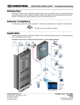
Application
The following diagram shows a GLPAC-DIMFLV Series Crestron Green Light Integrated Lighting System in a
lighting application.
GLPAC-DIMFLV Series Crestron Green Light Integrated Lighting System in a Typical Lighting Application
AC IN
LAN
Control
Cresnet
AC
2 • Crestron Green Light Integrated Lighting System: GLPAC-DIMFLV Installation Guide – DOC. 7004D

Integrated Lighting System Crestron GLPAC-DIMFLV
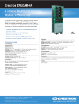
Physical Description
This section shows the dimensions of the GLPAC-DIMFLV Series Crestron Green Light Integrated Lighting
System.
Dimensions of GLPAC-DIMFLV4, 4-PM, 8, and 8-PM Integrated Lighting System Cabinet (Front, Side, and Bottom Views)
12 15/16 in
(313 mm)
14 1/8 in
(359 mm)
9 1/2 in
(242 mm)
4 3/8 in
(
111 mm)
2 15/16 in
(75 mm)
1 3/8 in
(35 mm)
1/8 in
(4 mm)
5 in
(127 mm)
3 9/16 in
(91 mm)
1 5/16 in
(34 mm)
11 1/2 in
(293 mm)
2 15/16 in
(75 mm)
1 3/8 in
(35 mm)
1 5/16 in
(34 mm)
Knockout (Qty. 16) for 3/4 in
(20 mm) and 1/2 in (13 mm)
Conduit (Typical Both Sides)
4 9/16 in
(116 mm)
5 in
(127 mm)
Installation Guide – DOC. 7004D Crestron Green Light Integrated Lighting System: GLPAC-DIMFLV • 3

Crestron GLPAC-DIMFLV Integrated Lighting System
Dimensions of GLPAC-DIMFLV4 and 4-PM Integrated Lighting System Cabinet
(Internal View, GLPAC-DIMFLV4 Shown Below)
NOTE: For module specifications, refer to “Appendix A: Specifications” on page 22.
12 in
(305 mm)
10 in
(254 mm)
1 1/16 in
(27 mm)
Qty. 4 Ø 1/4 in
(7 mm)
Mounting Holes
1 1/16 in
(27 mm)
If required, the
ground bus may
be moved to the
left side of the
enclosure.
4 • Crestron Green Light Integrated Lighting System: GLPAC-DIMFLV Installation Guide – DOC. 7004D

Integrated Lighting System Crestron GLPAC-DIMFLV
Dimensions of GLPAC-DIMFLV8 and 8-PM Integrated Lighting System Cabinet
(Internal View, GLPAC-DIMFLV8-PM Shown Below)
NOTE: For module specifications, refer to “Appendix A: Specifications” on page 22
.
If required, the
ground bus may
be moved to the
left side of the
enclosure.
12 in
(305 mm)
10 in
(254 mm)
1 1/16 in
(27 mm)
Qty. 4 Ø 1/4 in
(7 mm)
Mounting Holes
1 1/16 in
(27 mm)
Installation Guide – DOC. 7004D Crestron Green Light Integrated Lighting System: GLPAC-DIMFLV • 5

Crestron GLPAC-DIMFLV Integrated Lighting System
Installation
Observe the following when installing the cabinet:
• The cabinet must be mounted by a licensed electrician in accordance with all national and local codes.
Refer to the diagram below for specific requirements.
• Allow adequate clearance in front of the cover for servicing.
• The cabinet is designed for surface mounting on a wall.
• Cabinets are intended for indoor use only.
• The ambient temperature range should be 32° F to 104° F (0° C to 40° C). The relative humidity should
range from 10% to 90% (non-condensing).
Mounting Location
3
f
t
(~1
m)
Minimum
Clearance
Required
W
all
6 • Crestron Green Light Integrated Lighting System: GLPAC-DIMFLV Installation Guide – DOC. 7004D

Integrated Lighting System Crestron GLPAC-DIMFLV
Wiring
GLPAC-DIMFLV Wiring Diagram (Rotate 90 Degrees to View)
Fi
xtures
GLPAC
0-10 V Flour.
Ballast(s)
F
eed and
Load Wir
ing
10-14 AWG
Distribution P
anel
Cr
esnet
Co
nt
r
ol Wi
ring:
or CRESNE
T-P C
able
M
as
ter
Co
n
tr
ol
Sy
st
em
(Optional)
O
ve
rride
Co
n
tact
Closure
(24 V
)
C
onta
ct
Closures
(24 V
)
Cr
estron
Photoc
ell(s)
0-10 V Co
ntrol Wiring:
12-28 AWG 65 MA/CH,
Sink Only
Crestron
Occupanc
y
S
ensor(s)
Input
W
iring:
12-26
AWG
Sensor
W
ir
ing:
12-26 A
WG
24 V Supply: 10 W Total
HVAC
Sys
tem
L
ocal C
resnet
D
evic
e(s)
Crest
ron Shade and
Drape
Co
ntr
oller
HV
AC
Sy
st
em
Con
tact
Closur
e
Output
Mas
t
er C
on
t
rol
S
ys
tem
Br
eaker 20 A M
ax
Breaker 20 A
Max
Neut
ral
0-10 V Flour
.
Ballast(s)
Installation Guide – DOC. 7004D Crestron Green Light Integrated Lighting System: GLPAC-DIMFLV • 7

Crestron GLPAC-DIMFLV Integrated Lighting System
NOTE: All wiring must be installed in accordance with all local and national electrical codes.
NOTE: Refer to the torque settings specified on pages 9, 10, and 12.
Crestron Green Light Integrated Lighting System cabinets are shipped with GLPAC-DIMFLV dimming modules
installed. The following must be performed after mounting the cabinet.
• Connect incoming feed conductors to the breaker panel.
• Connect load wiring (section A of the following diagram).
• Connect control wiring (section B of the following diagram).
• Connect input wiring (sections C of the following diagram).
Feed Wiring Diagram
SIG
NAL RE
LAYS
-1-
-2- -3-
-4-24 1 2 G
LOCAL NET
OR G
OVRID
NC 1 2 G
T
O CTRL SY
S
1 2 3 4 5 6 7 8 G
CONT
ACT CLOSURES
24 1 2 3
4 G
OCC SENSORS
24 1 2 3 4 G
PH
OTOCELL
S
Feeds
from
Breaker
Panel
To
Loads
Feeds
from
Breaker
Panel
To
Loads
Ground
Lug
8 • Crestron Green Light Integrated Lighting System: GLPAC-DIMFLV Installation Guide – DOC. 7004D

Integrated Lighting System Crestron GLPAC-DIMFLV
Load Wiring (Section A)
Make connections for the load wiring. Refer to the illustrations that follow for guidance.
NOTE: Use copper conductors only – rated 75° C or greater.
Wire Gauge and Torque Values
TERMINAL CONNECTOR MAX
WIRE RANGE
TORQUE STRIP
LENGTH
LN Inputs 14-10 AWG 4.42 lb-in (0.5 Nm) 5/16 in (8 mm)
SW Outputs 14-10 AWG 4.42 lb-in (0.5 Nm) 5/16 in (8 mm)
N1, N1 Neutral Bus 14-10 AWG 4.42 lb-in (0.5 Nm) 5/16 in (8 mm)
0-10V Outputs* 28-12 AWG 4.42 lb-in (0.5 Nm) 5/16 in (8 mm)
Ground Lug 14-4 AWG 25-45 lb-in (2.8-5.1 Nm) 3/4 in (19 mm)
* May be wired as Class 1 or Class 2.
1. Turn off all circuit breakers.
2. Connect the neutral bus and ground lugs.
3. Connect incoming feed conductors to the LINE and N input terminals and connect loads to the SW output
terminals (refer to the following diagram).
NOTE: Additional line terminals are provided as a convenience to allow daisy chaining channels when the
device is fed from a single branch circuit.
NOTE: The unit requires LINE1 and neutral to be connected to power up.
4. Connect 0-10 V control wires for the dimmed loads to the appropriate output terminals (1 through 8).
5. Test the circuit for electrical faults by turning on each circuit breaker, checking that the breakers do not
trip, and ensuring that power is delivered to the proper loads.
Installation Guide – DOC. 7004D Crestron Green Light Integrated Lighting System: GLPAC-DIMFLV • 9

Crestron GLPAC-DIMFLV Integrated Lighting System
Load Wiring Diagram (Section A)
Control Wiring (Section B)
Use Crestron certified wire such as CRESNET-NP or CRESNET-P. To ensure optimum performance over the full
range of the installation topology, use Crestron certified wire. Failure to do so may incur additional charges if
support is required to identify performance deficiencies because of using improper wire.
Wire Gauge and Torque Values
CONNECTOR MAX WIRE RANGE TORQUE STRIP LENGTH
26-12 AWG 4.43 lb-in (0.5 Nm) 1/4 in (6 mm)
TO CTRL SYS Wiring
This terminal block allows a master control system to communicate with the GLPAC-DIMFLV. When this
connection is made, the GLPAC-DIMFLV continues to operate as a control processor that runs a Crestron Studio™
or SIMPL Windows program. It also continues to communicate with devices on its local Cresnet
®
bus.
OVRID Wiring
This terminal block accepts input from external contact closure to trigger a preset override state.
LOCAL NET Wiring
This terminal block can be used to connect to local Cresnet devices such as keypads, shade controllers, and touch
screens.
NOTE: A maximum of two keypads can be installed in each room.
N
N
+ 1 - + 2 - + 3 - + 4 - + 5 - + 6 - + 7 - + 8 -
}
}
}
}
}
}
}
}
Neutral Bus
Ground Lug
Circuit Breaker
(20 A Max)
To Switched Leg
of Dimmed Loads
To Switched Leg
of Dimmed Loads
T
o 0-10 V Dimmable 4-Wire Loads
Purple
Gray
Purple
Gray
Purple
Gray
Purple
Gray
Purple
Gray
Purple
Gray
Purple
Gray
Purple
Gray
Daisy chain
the channels
together
when feeding
from a single
branch circuit.
10 • Crestron Green Light Integrated Lighting System: GLPAC-DIMFLV Installation Guide – DOC. 7004D

Integrated Lighting System Crestron GLPAC-DIMFLV
USB Port
A USB Type B female computer console port is provided for communication with Crestron Toolbox™.
LAN Port
A 10/100BASE-T Ethernet to LAN port is provided to allow communication with Cresnet slave Ethernet devices
and Crestron control processors over Ethernet Inter System Communications (EISC). The LAN port also provides
web server and console access to the GLPAC-DIMFLV.
Control Wiring Diagram (Section B)
NOTE: For instructions on network wiring, refer to “Appendix B: Crestron Network Interconnect” on page 23
.
-1 - -2 - -3 - -4 -24 1 2 G
LOC A L N E T
OR G
OV R ID
NC 1 2 G
TO CT RL S Y S
1 2 3 4 5 6 7 8 G
CO N TA CT C L OS U RE S
24 1 2 3 4 G
OC C S E NS O RS
24 1 2 3 4 G
PH O TO C EL L
S
Red
White
Blue
Black
24 1 2 G
OR G
NC Y Z G
L
A
N
USB
TO CTRL SYS
OVRID LOCAL
NET
TO CTR
L SYS:
To Control
System
LOCAL NET:
To Other
Cresnet
Devices
Local
Devices
OVRID:
From Other Cabinet,
Alarm, etc. (Optional);
To Other Cabinet(s) if
Necessary
LAN:
To Cresnet Slave
Ethernet Devices, Other
Control Processors, etc.
USB:
T
o Personal
Computer
Central Control
Processor
Installation Guide – DOC. 7004D Crestron Green Light Integrated Lighting System: GLPAC-DIMFLV • 11

Crestron GLPAC-DIMFLV Integrated Lighting System
Input Wiring (Section C)
To ensure optimum performance over the full range of the installation topology, use Crestron certified wire (e.g.,
CRESNET-NP or CRESNET-P). Failure to do so may incur additional charges if support is required to identify
performance deficiencies because of using improper wire.
Wire Gauge and Torque Values
CONNECTOR MAX WIRE RANGE TORQUE STRIP LENGTH
26-12 AWG 4.43 lb-in (0.5 Nm) 1/4 in (6 mm)
SIGNAL RELAYS Wiring
This terminal block provides four low-voltage (30 Vdc max) programmable relays. These non-latching relays are
designed to send a signal to a variable air volume (VAV) box to indicate room occupancy status.
CONTACT CLOSURES Wiring
This terminal block can be used to connect up to eight general-purpose contact closure inputs.
OCC SENSORS Wiring
This terminal block can be used to connect up to four room occupancy sensors, such as the Crestron GLS-ODT or
Crestron GLS-OIR (sold separately). Up to four sensors can be powered with 24 Vdc.
PHOTOCELLS Wiring
This terminal block can be used to connect up to four photocells, such as the Crestron GLS-LOL and Crestron
GLS-LCL (sold separately). Up to four sensors can be powered with 24 Vdc.
12 • Crestron Green Light Integrated Lighting System: GLPAC-DIMFLV Installation Guide – DOC. 7004D

Integrated Lighting System Crestron GLPAC-DIMFLV
Input Wiring Diagram (Section C)
SI
GN
A
L R
EL
A
YS
1 2
3 4 5 6 7
8
G
24
1
2 3
4
G
-
1
- -
2-
-
3-
-
4-
24 1
2 3
4
G
-
1-
-
2-
-
3-
-4
-
2
4
1
2 G
LOC AL NET
O
R
G
OVRID
N
C
1
2
G
TO CT RL SYS
1 2
3 4
5
6 7
8 G
C
O
N
T
A
C
T
C
L
O
S
U
R
E
S
2
4
1 2
3 4
G
O
C
C
S
E
N
S
O
R
S
2
4 1
2 3
4
G
P
H
O
T
O
C
E
L
L
S
SIGNAL RELAYS
Black
Black
Black
Red
Red
OCC SENSORS
PHOT
OCELLS
CON
T
ACT
CLOSURES
(Low Voltage)
Keypad
(1-4)
Room
Occupancy
Sensor 1 of 4
Analog
Photocell
Input 1 of 4
VAV Box
1 of 4
Installation Guide – DOC. 7004D Crestron Green Light Integrated Lighting System: GLPAC-DIMFLV • 13

Crestron GLPAC-DIMFLV Integrated Lighting System
Front Panel Setup
The following procedures are normally performed by an authorized Crestron representative as part of the System
Commissioning phase.
NOTE: For advanced configuration options, refer to the GLPAC-DIMFLV Series Setup Guide (Doc. 7005) at
www.crestron.com/manuals.
To enter Setup mode using the front panel, do the following:
1. Press and hold the SAVE and CANCEL buttons for 5 seconds to enter Setup mode. The display shows the
first mode that can be modified, denoted by “r”.
NOTE: Setup mode times out and exits after 5 minutes of inactivity.
2. As shown in the following diagram, press the left up or down buttons to select the appropriate mode to
configure.
Front Panel Configuration Buttons
3. Press the right up or down buttons to select the appropriate value for the mode being configured. The
SAVE and CANCEL LEDs illuminate.
NOTE: Once a value has been selected, the user is unable to go back to select a different mode.
4. Press the SAVE button to save the change and return to setup, or press the CANCEL button to exit Setup
mode.
Setup mode offers the ability to modify the following parameters:
• Room Count (refer to page 15)
• Learnable Buttons (refer to page 16)
• Cresnet ID (refer to page 16)
• Occupancy Sensor (refer to page 16)
• Photocell Setup (refer to page 16)
• Auto Discovery (refer to page 16)
• Ethernet Setting (refer to page 17)
Left Up and Down
Buttons (Mode
Selection)
Right Up and Down
Buttons (Value
Selection)
SAVE and CANCEL
Buttons
14 • Crestron Green Light Integrated Lighting System: GLPAC-DIMFLV Installation Guide – DOC. 7004D

Integrated Lighting System Crestron GLPAC-DIMFLV
Room Count Mode (r)
The Room Count mode defines the number of rooms in the system.
• 01: 1 Room
• 02: 2 Rooms
• 03: 3 Rooms
• 04: 4 Rooms
Based on the number of rooms defined, loads and devices are assigned automatically as per the following table:
Automatic Load and Device Assignments
1 ROOM
2 ROOMS
3 ROOMS
4 ROOMS
(PER
ROOM)
1ST ROOM
(PER ROOM)
2ND AND 3RD
ROOM (PER ROOM)
(PER
ROOM)
Loads
4 (or 8 for
GLPAC-
DIMFLV-8)
2 2 (or 4 for
GLPAC-
DIMFLV-8)
1 (or 2 for
GLPAC-DIMFLV-8)
1 (or 2 for
GLPAC-
DIMFLV-8)
Photocell
1 1 1 1 1
Occupancy
Sensor
1 1 1 1 1
Contact
Closures
8 4 2 2 2
Scenes
8 8 8 8 8
Based on the number of rooms defined, the contact closures are assigned the following functions by default:
Automatic Contact Closure Assignments
INPUT
#1
INPUT
#2
INPUT
#3
INPUT
#4
INPUT
#5
INPUT
#6
INPUT
#7
INPUT
#8
1 Room
Room 1
Auto On
Room 1
Off
Room 1
Master
Raise
Room 1
Master
Lower
Room 1
Scene 1
Room 1
Scene 2
Room 1
Scene 3
Room 1
Scene 4
2 Rooms
Room 1
Auto On
Room 1
Off
Room 1
Master
Raise
Room 1
Master
Lower
Room 2
Auto On
Room 2
Off
Room 2
Master
Raise
Room 2
Master
Lower
3 Rooms
Room 1
Auto On
Room 1
Off
Room 2
Auto On
Room 2
Off
Room 3
Auto On
Room 3
Off
4 Rooms
Room 1
Auto On
Room 1
Off
Room 2
Auto On
Room 2
Off
Room 3
Auto On
Room 3
Off
Room 4
Auto On
Room 4
Off
NOTE: The Auto or On function works with both a momentary switch and a sustained switch.
NOTE: For the Auto or On function, when a signal is detected on the contact closure, the Auto or On function is
executed. In the event that the signal is held high for longer than 1 second, the loads perform an “off” function on
the falling edge of the signal.
Installation Guide – DOC. 7004D Crestron Green Light Integrated Lighting System: GLPAC-DIMFLV • 15

Crestron GLPAC-DIMFLV Integrated Lighting System
Learnable Buttons Mode (Lb)
The Learnable Buttons mode defines whether or not keypads can save scene levels.
• n: Buttons recall scenes only (default).
• y: Scene buttons save levels when held for 5 seconds. Buttons return to default levels when held for 10
seconds.
NOTE: Saving scene levels also allows target levels to be saved for photocell controlled loads
(Scenes 1 through 4 only).
Cresnet ID Mode (id)
The Cresnet ID mode sets the internal Cresnet ID of the GLPAC when communicating with a master control
processor. Press the right up button to cycle the first digit and press the right down button to cycle the second digit.
Available values are 03 to FE.
Occupancy Sensor Mode (1.0, 2.0, 3.0, 4.0)
The Occupancy Sensor mode defines a scene when occupancy is detected. Depending on configuration, up to four
rooms can be defined (1.0, 2.0, 3.0, 4.0).
• Au: Recall auto level (only if photocell is defined, otherwise loads go full on)
• --: No action (default)
• 1-8: Recall scene (1 through 8)
NOTE: The Vacant scene turns off all lights in the room.
NOTE: Press the SAVE button to save any newly discovered devices and exit Setup mode or press the CANCEL
button to exit Setup mode.
NOTE: The low voltage relays mirror the occupancy sensor input value (i.e., when the occupancy input goes high,
the low voltage relay output goes high).
Photocell Setup Mode (1.P, 2.P, 3.P, 4.P)
The Photocell Setup mode defines the photocell type connected to one of the four inputs (1.P, 2.P, 3.P, 4.P).
• OL: Open loop
• CL: Closed loop
NOTE: Photocell Setup mode affects all loads in the room in the same way.
Auto Discovery Mode (1.d, 2.d, 3.d, 4.d)
The Auto Discovery mode finds devices in the selected room (1.d, 2.d, 3.d, 4.d). Press the right up or down button to
begin the process of auto discovery.
When initiated, all devices on the network enter Light and Poll mode (including devices previously discovered). A
device is assigned to the currently selected room when any button on the device is pressed.
NOTE: Once two keypads have been identified, all other keypads exit Light and Poll mode. Once two shade
controllers have been identified, all other shade controllers exit Light and Poll mode.
NOTE: Auto Discovery mode times out and exits after 5 minutes of inactivity.
16 • Crestron Green Light Integrated Lighting System: GLPAC-DIMFLV Installation Guide – DOC. 7004D

Integrated Lighting System Crestron GLPAC-DIMFLV
Ethernet Setting Mode (E, F)
The Ethernet Setting mode defines the GLPAC-DIMFLV Ethernet setting.
• D: Dynamic addressing (DHCP On)
• F: Static IP address
NOTE: The GLPAC-DIMFLV reboots after pressing the SAVE button.
Installation Guide – DOC. 7004D Crestron Green Light Integrated Lighting System: GLPAC-DIMFLV • 17

Crestron GLPAC-DIMFLV Integrated Lighting System
Keypad Configuration
The following functions are available for keypad buttons when the keypad is connected to the GLPAC-DIMFLV:
• Lights Auto: Light level controlled by photocell. When the photocell is not installed, the default function
becomes Lights On.
• Lights Auto or Off: Toggles between auto mode and full off.
• Lights Off: All off.
• Master Shades Open: Momentary press fully opens all shades.
• Master Shades Close: Momentary press fully closes all shades.
• Master Shades Cycle: Alternately opens or closes the shades.
• Recall Scene #: Recalls scene number.
• Shade Group (1 and 2) Open: Open shades in shade group (1 and 2).
• Shade Group (1 and 2) Close: Close shades in shade group (1 and 2).
• Group (1 and 2) Shade Cycle: Cycle between open or close momentary.
• Shades Preset (1 to 4): Recalls shade preset (1 to 4).
• Master Raise: Raise the light level of all lights.
• Master Lower: Lower the light level of all lights.
• Scene Save: Allows scenes and target levels for photocell-controlled loads (Scenes 1 to 4 only) to be saved.
Refer to “Learnable Buttons Mode (Lb)” on page 16 for more information.
NOTE: The GLPAC-DIMFLV allocates two Cresnet IDs for each keypad model by default.
Keypad Programming
Keypads can be programmed to use one of three pre-defined templates available in the GLPAC-DIMFLV:
• A: Lights only
• B: Shades only
• C: Lights and shades
NOTE: Refer to “Appendix C: Keypad Templates” on page 25
for keypad-specific button layouts.
Select a template by pressing and holding any two buttons on the keypad for 10 seconds. The keypad cycles through
the available templates (A, B, and C). After cycling, the top LED indicates the selected template by blinking once
for template A, twice for template B, or three times for template C. The top LED then extinguishes for 2 seconds.
This pattern repeats twice (for a total of three times).
18 • Crestron Green Light Integrated Lighting System: GLPAC-DIMFLV Installation Guide – DOC. 7004D

Integrated Lighting System Crestron GLPAC-DIMFLV
Configuring Keypads with Adjustable Button Layouts
Keypads with adjustable button layouts (C2N-* Series) can be programmed to use one of three pre-defined
templates available in the GLPAC-DIMFLV. Additional templates are available for keypads with specific button
layouts via Button Layout mode.
Use the following procedure to program a keypad for a specific button layout.
1. To place the keypad into the Button Layout mode, tap the lowest button (button 6 or, for split button
configurations, 8) on the keypad three times rapidly, and then press and hold until all LEDs extinguish. The
LEDs corresponding to the currently recognized layout blink on and off.
NOTE: For multiheight buttons, the blinking LED corresponds to the lowest adjacent LED (associated
with the button press).
NOTE: If split buttons are used, the eight button layout must be used. Program the buttons that are not
present as “not used” in the XPanel interface.
2. Starting from the top and moving down, press each button. Once a button has been pressed, all blinking
LEDs turn off and the LED corresponding to the pressed button illuminates. Button Layout mode exits
2 seconds after the last button has been pressed or after 2 seconds of inactivity.
NOTE: If Button Layout mode is exited without a valid button layout, or if all buttons have not been
pressed, the keypad reverts to its previous layout.
Installation Guide – DOC. 7004D Crestron Green Light Integrated Lighting System: GLPAC-DIMFLV • 19

Crestron GLPAC-DIMFLV Integrated Lighting System
Testing
Manual Control
Lighting loads can be manually controlled from the front panel.
Override Mode
The Override mode overrides the control system program and sets all of the output states to the stored override
values. For instructions on saving override settings, refer to “Save Override Settings” below.
To enable Override mode, press and release the OVR button. The OVR LED flashes slowly.
NOTE: If the Override mode was enabled from an external device (i.e., a contact closure is present on the OVRID
terminals), the OVR LED flashes quickly. Pressing the OVR button has no effect.
To disable Override mode, press the OVR button again. The OVR LED extinguishes and the outputs return to the
states set by the control system program.
NOTE: If override states have not been stored, the factory default override state turns all loads on.
Save the Override Settings
The state of all of the outputs can be saved as an override setting that can be automatically recalled when the
Override mode is enabled.
NOTE: The control system program has a setting that can prevent locally saving the override state. If this setting is
enabled, the display shows “Er” when trying to save the override states. For more information, refer to the Crestron
Studio or SIMPL Windows help file.
To save the states of all of the outputs as the override setting, press and hold the OVR button for 3 seconds until the
LED blinks once.
System Operation and Commissioning
This cabinet has been designed as a component of a programmed Crestron system. System commissioning by an
authorized Crestron representative must be performed to ensure system operation.
Once the cabinet has been wired and the modules have been tested, contact Crestron at 1-888-CRESTRON
[1-888-273-7876] to schedule commissioning.
20 • Crestron Green Light Integrated Lighting System: GLPAC-DIMFLV Installation Guide – DOC. 7004D
/