3M DBI-SALA® Sayfline™ Synthetic Horizontal Lifeline System 7600503, 1 ea Operating instructions
- Type
- Operating instructions
This manual is also suitable for
- DBI-SALA® Sayfline™ Synthetic Horizontal Lifeline System 7600502, 1 ea
- DBI-SALA® Sayfline™ Synthetic Horizontal Lifeline System 7600504, 1 EA
- DBI-SALA® Sayfline™ Synthetic Horizontal Lifeline System 7600505, 1 ea
- DBI-SALA® Sayfline™ Synthetic Horizontal Lifeline System 7600506, 1 EA
- DBI-SALA® Sayfline™ Synthetic Horizontal Lifeline System 7600507, 1 ea
- DBI-SALA® Sayfline™ Synthetic Horizontal Lifeline System 7600508, 1 EA
- DBI-SALA® Sayfline™ Synthetic Horizontal Lifeline System 7600509, 1 ea
- DBI-SALA® Sayfline™ Synthetic Horizontal Lifeline System 7600510, 1 EA

© Copyright 2014, Capital Safety
The Ultimate in Fall Protection
User Instruction Manual Synthetic Rope
Horizontal Lifeline System
This manual is intended to be used as part of an employee training program as
required by OSHA.
Instructions for the following series products:
SYNTHETIC ROPE HORIZONTAL LIFELINE
See the last pages for specifi c model numbers
Form: 5902179 Rev: C


3
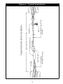
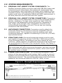
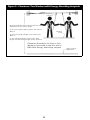
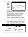
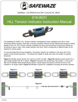
Figure 1 - Typical Installation
Typical Horizntal Lifeline Installation
Span length 100 ft (30.m) Max.
Snap Hook
Labels
Rope Tensioner
Tie-off Adapter
(Anchorage Connector)
Attachment O-ring for User
(Lanyard)
Anchorage
In-line Energy Absorber

4
WARNING: This product is part of a personal fall arrest system. The
user must follow the manufacturer’s instructions for each component
of the system. These instructions must be provided to the user of this
equipment. The user must read and understand these instructions
before using this equipment. Manufacturer’s instructions must be
followed for proper use and maintenance of this equipment. Alterations
or misuse of this equipment, or failure to follow instructions, may
result in serious injury or death.
IMPORTANT: If you have questions on the use, care, or suitability of
this equipment for your application, contact DBI-SALA.
IMPORTANT: Record the product identifi cation information from the
ID label in the inspection and maintenance log in section 9.0 of this manual.
1.0 APPLICATION
1.1 PURPOSE: The Sayfl ine Synthetic Rope Horizontal Lifeline System
is designed for use as an anchoring means for one or two persons.
Use the Sayfl ine Horizontal Lifeline System where horizontal
mobility and fall protection are required.
1.2 LIMITATIONS: The following limits apply to the installation and
use of the Sayfl ine Synthetic Rope Horizontal Lifeline System.
Other limitations may apply:
IMPORTANT: OSHA regulations state that horizontal lifelines
shall be installed and used under the supervision of a qualifi ed
person (see below for defi nition) as part of a complete personal
fall arrest system that maintains a safety factor of at least two.
QUALIFIED PERSON: An individual with a recognized degree or
professional certifi cate, and extensive knowledge and experience
in the subject fi eld, who is capable of design, analysis,
evaluation, and specifi cation in the subject work, project, or
product. Refer to OSHA 1910.66, 1926.32, and 1926.502.
A. HORIZONTAL LIFELINE SPAN: The maximum span distance
is 100 feet. The span length must be reduced when clearance
is limited. See section 3.2 for clearance information.
B. ANCHORAGES: The Sayfline horizontal lifeline must be
installed on anchorages that meet the requirements specified
in section 2.4.
C. SYSTEM CAPACITY: The maximum capacity of the Sayfline
horizontal lifeline is two persons. The maximum weight of each
person, including tools and clothing, is 310 lbs. (141kg).
D. CONNECTING SUBSYSTEM: Each person’s connecting
subsystem must limit fall arrest forces to 900 lbs. (4kN) or
less. See section 2.5.

5
E. FREE FALL: Rig and use the personal fall arrest system
such that the maximum potential free fall does not exceed
Government regulatory and subsystem manufacturer’s
requirements. See section 3.0 and subsystem manufacturer’s
Instructions for more information.
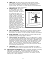
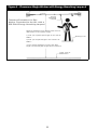
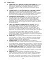
F. SWING FALLS: See Figure
2. Swing falls occur when
the anchorage point is not
directly overhead. The force
of striking an object in a
swing fall may cause serious
injury or death. Minimize
swing falls by working as
directly below the anchorage
point as possible. Do not
permit a swing fall if injury
could occur. Swing falls will
significantly increase the
clearance required when a
self retracting lifeline or other
variable length connecting
subsystem is used. If a swing
fall situation exists in your
application, contact DBI-SALA
before proceeding.
G. FALL CLEARANCE: There must be sufficient clearance below
the worker to arrest a fall before striking the lower level or
obstruction. See section 3.2 for required clearance information.
H. BODY SUPPORT: A full body harness must be used with the
Synthetic Rope Horizontal Lifeline System.
I. ENVIRONMENTAL HAZARDS: Use of this equipment in areas
with environmental hazards may require additional precautions
to reduce the possibility of injury to the user or damage to the
equipment. Hazards may include, but are not limited to; heat,
chemicals, corrosive environments, high voltage power lines,
gases, moving machinery, and sharp edges. Contact DBI–
SALA if you have questions about using this equipment where
environmental hazards exist.
J. TRAINING: This equipment must be installed and used by
persons trained in its correct application and use. See section 4.0.
1.3 APPLICABLE STANDARDS: Refer to national standards, including
ANSI Z359.1, local, state, and federal (OSHA 1910.66 and
1926.502) requirements for more information on personal fall
arrest systems and associated components. In Canada, see the
Z259 group of CSA standards.
Figure 2 - Swing Fall

6
2.0 SYSTEM REQUIREMENTS
2.1 PERSONAL FALL ARREST SYSTEM COMPONENTS: The
Sayfl ine horizontal lifeline must be used with DBI-SALA approved
components and subsystems. Non-approved components may
be incompatible, and could affect the safety and reliability of the
complete system. Personal fall arrest components used with this
system must meet all applicable OSHA and ANSI requirements. A
full body harness must be used with this system.
2.2 PERSONAL FALL ARREST SYSTEM CONNECTORS: Connectors
used to attach to the attachment O-ring on the horizontal lifeline
(hooks, carabiners, D-rings) must support at least 5,000 lbs.
Connectors and attachment elements must be compatible in
size, shape, and strength. Non-compatible connectors may
unintentionally disengage (roll-out). Do not use non-locking
connectors with this system.
2.3 ANCHORAGE CONNECTORS: Connectors used to attach the
horizontal lifeline to end anchors must be compatible with the
connection point. The connection must be positive; and, with
connecting elements, capable of sustaining a 5,000 lbs. (22.2kN)
load without failure.
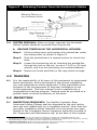
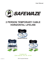
2.4 STRUCTURE LOAD: Structural anchorage points must be rigid,
and capable of supporting at least 3,600 lbs. (16kN) along the axis
of the horizontal lifeline. Anchorages must also support at least
3,600 lbs. (16kN) applied in all potential directions of fall arrest that
are perpendicular to the axis of the horizontal lifeline. See Figure 3.
WARNING: Anchorages must be rigid. Large deformations of
the anchorage will affect system performance, and may increase
the required fall clearance below the system, which could result
in serious injury or death.
2.5 CONNECTING SUBSYSTEM: The connecting subsystem is the
portion of the personal fall arrest system that is used to connect
between the horizontal lifeline subsystem and harness fall arrest
attachment element. The connecting subsystem must limit forces
applied to the horizontal lifeline to 900 lbs. (4kN) or less.
Figure 3 - Strength Requirements
Anchorage Strength Requirements
3,600 lbs (16kN) Minimum 3,600 lbs (16kN) Minimum
3,600 lbs (16kN) Minimum in all potential directions of fall
arrest that are perendicular to the axis of the lifeline

7
3.0 OPERATION AND USE
WARNING: Do not alter or intentionally misuse this equipment. Consult
DBI-SALA when using this equipment in combination with components or
subsystems other than those described in this manual. Some subsystem
and component combinations may interfere with the operation of this
equipment. Use caution when using this equipment around moving
machinery, electrical hazards, chemical hazards, and sharp edges.
WARNING: Consult your doctor if there is reason to doubt your
fi tness to absorb the impact from a fall arrest. Age and fi tness can
affect your ability to withstand fall arrest forces. Pregnant women and
minors must not use this system.
3.1 BEFORE EACH USE inspect this equipment according to section
5.0. Do not use this equipment if inspection reveals an unsafe or
defective condition. Plan your use of the fall protection system
prior to exposing workers to dangerous situations. Consider all
factors affecting your safety before using this system.
A. Read and understand all manufacturer’s instructions for each
component of the personal fall arrest system. All DBI-SALA
harnesses and connecting subsystems are supplied with separate
user instructions. Keep all instructions for future reference.
B.
Review sections 1.0 and 2.0 to ensure system limitations and
other requirements have been adhered to. Review applicable
information regarding system clearance criteria, and ensure
changes have not been made to the system installation (i.e.
length) or occurred at the job site that could affect the required
fall clearance. Do not use the system if changes are required.
3.2 SYSTEM INSTALLATION: Figure 1 shows a typical Sayfl ine
horizontal lifeline installation. When using an energy absorbing
lanyard to connect to the system, the end anchorages must be
located at a height which will limit the free fall to 6 feet (1.8m).
When using a self retracting lifeline (SRL) to connect to the
system, the end anchorages must be located above the user. The
SRL, when fully retracted, must be above the harness attachment
level. The horizontal lifeline system should be positioned at a
level that will minimize free fall while allowing ease of use. The
horizontal lifeline should be positioned near the work location to
minimize swing fall hazards. The connecting subsystem length
should be kept as short as possible to reduce the potential free
fall and required clearance distance. Both anchorages must
be installed at approximately the same elevation, so that the
horizontal lifeline system is not sloped more than 5°.
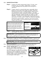
Step 1. Determine the locations of the end anchorages and
evaluate their strengths in accordance with section 2.4.
Determine the span length and evaluate the required
clearance using Figures 4, 5, or 6 and Tables 1, 2 or 3.

8
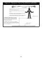
Figure 4 - Clearance: Single Worker with Energy Absorbing Lanyard
Clearance Evaluation for One
Worker Connected to the HLL with a
DBI-SALA Energy Absorbing Lanyard
Energy
Absorbing
Lanyard
Required clearance from nearest lower level or
obstruction to HLL system height
1) Find your system span length in the rows of
Table 1.
2) Find your lanyard length in the columns of
Table 1.
3) The requied clearance is where the span
length row and lanyard length column intersect.
Working Level
Lower Level or
Obstruction
Span Length

9
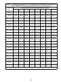
Table 1 - Required Clearance for One Worker Connected to the System
with a DBI-SALA Energy Absorbing Lanyard (See Figure 4)
Span length
in feet
Length of Enerrgy Absorbing Lanyard in feet
3
(.91)
4
(1.22)
5
(1.52)
6
(1.83)
7
(2.13)
8
(2.44)
9
(2.74)
10
(3.1)
0-10
(0-3.05)
16’-1”
(4.90)
17’-1”
(5.20)
18’-1”
(5.51)
19’-1”
(5.82)
20’-1”
(6.12)
21’-1”
(6.43)
22’-1”
(6.73)
23’-1”
(7.04)
10-15
(3.05-4.57)
16’-3”
(4.95)
17’-3”
(5.26)
18’-3”
(5.56)
19’-3”
(5.87)
20’-3”
(6.12)
21’-3”
(6.48)
22’-3”
(6.78)
23’-3”
(7.09)
15-20
(4.57-6.10)
16’-5”
(5.00)
17’-5”
(5.31)
18’-5”
(5.61)
19’-5”
(5.92)
20’-5”
(6.27)
21’-5”
(6.53)
22’-5”
(6.83)
23’-5”
(7.14)
20-25
(6.10-7.62)
16’-7”
(5.06)
17’-7”
(5.36)
18’-7”
(5.66)
19’-7”
(5.97)
20’-7”
(6.27)
21’-7”
(6.58)
22’-7”
(6.88)
23’-7”
(7.19)
25-30
(7.62-9.14)
16’-9”
(5.11)
17’-9”
(5.41)
18’-9”
(5.72)
19’-9”
(5.97)
20’-9”
(6.33)
21’-9”
(6.63)
22’-9”
(6.93)
23’-9”
(7.24)
30-35
(9.14-10.67)
17’-6”
(5.33)
18’-6”
(5.64)
19’-6”
(5.94)
20’-6”
(6.25)
21’-6”
(6.55)
22’-6”
(6.86)
23’-6”
(7.16)
24’-6”
(7.47)
35-40
(10.67-12.19)
18’-3”
(5.56)
19’-3”
(5.87)
20’-3”
(6.17)
21’-3”
(6.48)
22’-3”
(6.78)
23’-3”
(7.09)
24’-3”
(7.39)
25’-3”
(7.70)
40-45
(12.19-13.72)
18’-11”
(5.77)
19’-11”
(6.07)
20’-11”
(6.38)
21’-11”
(6.68)
22’-11”
(6.99)
23’-11”
(7.29)
24’-11”
(7.60)
25’-11”
(7.90)
45-50
(13.72-15.24)
19’-6”
(5.94)
20’-6”
(6.25)
21’-6”
(6.55)
22’-6”
(6.86)
23’-6”
(7.16)
24’-6”
(7.47)
25’-6”
(7.77)
26’-6”
(8.08)
50-55
(15.2-16.76)
20’-2”
(6.15)
21’-2”
(6.45)
22’-2”
(6.76)
23’-2”
(7.06)
24’-2”
(7.37)
25’-2”
(7.67)
26’-2”
(7.98)
27’-2”
(8.28)
55-60
(16.76-18.29)
20’-10”
(6.35)
21’-10”
(6.66)
22’-10”
(6.96)
23’-10”
(7.26)
24’-10”
(7.57)
25’-10”
(7.87)
26’-10”
(8.18)
27’-10”
(8.48)
60-65
(18.29-19.81)
21’-5”
(6.53)
22’-5”
(6.83)
23’-5”
(7.14)
24’-5”
(7.44)
25’-5”
(7.75)
26’-5”
(8.05)
27’-5”
(8.36)
28’-5”
(8.66)
65-70
(19.81-21.34)
22’-1”
(6.73)
23’-1”
(7.04)
24’-1”
(7.34)
25’-1”
(7.65)
26’-1”
(7.95)
27’-1”
(8.26)
28’-1”
(8.56)
29’-1”
(8.87)
70-75
(21.34-22.86)
22’-8”
(6.91)
23’-8”
(7.21)
24’-8”
(7.52)
25’-8”
(7.82)
26’-8”
(8.13)
27’-8”
(8.43)
28’-8”
(8.74)
29’-8”
(9.04)
75-80
(22.86-24.38)
23’-4”
(7.11)
24’-4”
(7.42)
25’-4”
(7.72)
26’-4”
(8.03)
27’-4”
(8.33)
28’-4”
(8.64)
29’-4”
(8.94)
30’-4”
(9.25)
80-85
(24.38-25.91)
24’-0”
(7.32)
25’-0”
(7.62)
26’-0”
(7.93)
27’-0”
(8.23)
28’-0”
(8.53)
29’-0”
(8.84)
30’-0”
(9.14)
31’-0”
(9.45)
85-90
(25.91-27.43)
24’-7”
(7.49)
25’-7”
(7.80)
26’-7”
(8.10)
27’-7”
(8.41)
28’-7”
(8.71)
29’-7”
(9.02)
30’-7”
(9.32)
31’-7”
(9.63)
90-95
(27.43-28.96)
25’-3”
(7.70)
26’-3”
(8.00)
27’-3”
(8.31)
28’-3”
(8.61)
29’-3”
(8.92)
30’-3”
(9.22)
31’-3”
(9.53)
32’-3”
(9.83)
95-100
(28.96-30.48)
25’-10”
(7.87)
26’-10”
(8.18)
27’-10”
(8.48)
28’-10”
(8.79)
29’-10”
(9.09)
30’-10”
(9.40)
31’-10”
(9.70)
32’-10”
(10.01)
Meters are shown in parenthesis

10
Figure 5 - Clearance: Two Workers with Energy Absorbing Lanyards
Clearance Evaluation for One or Two
Workers Connected to the HLL with a
DBI-SALA Energy Absorbing Lanyard
Energy Absorbing
Lanyard
Required clearance from nearest lower level or
obstruction to HLL system height
1) Find your system span length in the rows of
Table 2.
2) Find your lanyard length in the columns of
Table 2.
3) The requied clearance is where the span
length row and lanyard length column intersect.
Working
Level
Lower Level or
Obstruction
Span Length

11
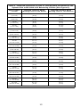
Table 2 - Required Clearance for Two Workers Connected to the System
with a DBI-SALA Energy Absorbing Lanyard (See Figure 5)
Span
length
in
feet
Length of Enerrgy Absorbing Lanyard in feet
3
(.91)
4
(1.22)
5
(1.52)
6
(1.83)
7
(2.13)
8
(2.44)
9
(2.74)
10 (3.1)
0-10
(0-3.05)
16’-5”
(5.00)
17’-5”
(5.31)
18’-5”
(5.61)
19’-5”
(5.92)
20’-5”
(6.27)
21’-5”
(6.53)
22’-5”
(6.83)
23’-5”
(7.14)
10-15
(3.05-4.57)
17’-5”
(5.31)
18’-5”
(5.61)
19’-5”
(5.92)
20’-5”
(6.27)
21’-5”
(6.53)
22’-5”
(6.83)
23’-5”
(7.14)
24’-5”
(7.44)
15-20
(4.57-6.10)
18’-5”
(5.61)
19’-5”
(5.92)
20’-5”
(6.27)
21’-5”
(6.53)
22’-5”
(6.83)
23’-5”
(7.14)
24’-5”
(7.44)
25’-5”
(7.75)
20-25
(6.10-7.62)
19’-4”
(5.89)
20’-4”
(6.20)
21’-4”
(6.50)
22’-4”
(6.81)
23’-4”
(7.11)
24’-4”
(7.42)
25’-4”
(7.72)
26’-4”
(8.03)
25-30
(7.62-9.14)
20’-4”
(6.20)
21’-4”
(6.50)
22’-4”
(6.81)
23’-4”
(7.11)
24’-4”
(7.42)
25’-4”
(7.72)
26’-4”
(8.03)
27’-4”
(8.33)
30-35
(9.14-10.67)
21’-7”
(6.58)
22’-7”
(6.88)
23’-7”
(7.19)
24’-7”
(7.49)
25’-7”
(7.80)
26’-7”
(8.10)
27’-7”
(8.41)
28’-7”
(8.71)
35-40
(10.67-12.19)
22’-9”
(6.93)
23’-9”
(7.24)
24’-9”
(7.54)
25’-9”
(7.85)
26’-9”
(8.15)
27’-9”
(8.46)
28’-9”
(8.76)
29’-9”
(9.07)
40-45
(12.19-13.72)
23’-10”
(7.26)
24’-10”
(7.57)
25’-10”
(7.87)
26’-10”
(8.18)
27’-10”
(8.48)
28’-10”
(8.79)
29’-10”
(9.09)
30’-10”
(9.40)
45-50
(13.72-15.24)
24’-11”
(7.60)
25’-11”
(7.90)
26’-11”
(8.20)
27’-11”
(8.51)
28’-11”
(8.81)
29’-11”
(9.12)
30’-11”
(9.42)
31’-11”
(9.73)
50-55
(15.2-16.76)
26’-0”
(7.93)
27’-0”
(8.23)
28’-0”
(8.53)
29’-0”
(8.84)
30’-0”
(9.14)
31’-0”
(9.45)
32’-0”
(9.75)
33’-0”
(10.06)
55-60
(16.76-18.29)
27’-2”
(8.28)
28’-2”
(8.59
29’-2”
(8.89
30’-2”
(9.20
31’-2”
(9.50
32’-2”
(9.80
33’-2”
(10.11
34’-2”
(10.41
60-65
(18.29-19.81)
28’-3”
(8.61)
29’-3”
(8.92)
30’-3”
(9.22)
31’-3”
(9.53)
32’-3”
(9.83)
33’-3”
(10.14
34’-3”
(10.44
35’-3”
(10.74
65-70
(19.81-21.34)
29’-4”
(8.94)
30’-4”
(9.25)
31’-4”
(9.55)
32’-4”
(9.86)
33’-4”
(10.16)
34’-4”
(10.47)
35’-4”
(10.77)
36’-4”
(11.07)
70-75
(21.34-22.86)
30’-5”
(9.27)
31’-5”
(9.58)
32’-5”
(9.88)
33’-5”
(10.19)
34’-5”
(10.49)
35’-5”
(10.80)
36’-5”
(11.10)
37’-5”
(11.41)
75-80
(22.86-24.38)
31’-6”
(9.60)
32’-6”
(9.91)
33’-6”
(10.21)
34’-6”
(10.52)
35’-6”
(10.82)
36’-6”
(11.13)
37’-6”
(11.43)
38’-6”
(11.74)
80-85
(24.38-25.91)
32’-7”
(9.93)
33’-7”
(10.24)
34’-7”
(10.54)
35’-7”
(10.85)
36’-7”
(11.15)
37’-7”
(11.46)
38’-7”
(11.76)
39’-7”
(12.07)
85-90
(25.91-27.43)
33’-8”
(10.26)
34’-8”
(10.57)
35’-8”
(10.87)
36’-8”
(11.18)
37’-8”
(11.48)
38’-8”
(11.79)
39’-8”
(12.09)
40’-8”
(12.40)
90-95
(27.43-28.96)
34’-9”
(10.59)
35’-9”
(10.90)
36’-9”
(11.20)
37’-9”
(11.51)
38’-9”
(11.81)
39’-9”
(12.12)
40’-9”
(12.42)
41’-9”
(12.73)
95-100
(28.96-30.48)
35’-10”
(10.92)
36’-10”
(11.23)
37’-10”
(11.54)
38’-10”
(11.84)
39’-10”
(12.14)
40’-10”
(12.45)
41’-10”
(12.75)
42’-10”
(13.06)
Meters are shown in parenthesis

12
Figure 6 - Clearance: One or Two Workers with SRLs
Clearance Evaluation for One
or Two Workers Connected to
the HLL with a DBI-SALA Self
Retracting Lifeline
WARNING: This information only applies
when the SRL is directly overhead and above
the level of the harness attachment point and
the user is standing.
Self Retracting
Lifeline
Required clearance from nearest lower level or
obstruction to working level
1) Find your system span length in the rows of
Table 3.
2) Find the number of workers to be connected to
the system in the columns of Table 3.
3) The requied clearance is where the span length
row and number of workers column intersect.
Working Level
Lower Level or
Obstruction
Span Length

13
Table 3 - Required Clearance for One or Two Workers Connected to the
System with a DBI-SALA Self Retracting Lifeline (See Figure 6).
Span Lenght
in feet
Required Clearance Below
Working Level for One Worker
Required Clearance Below
Working Level for Two Workers
0-10
(0-3.05)
7’-11”
(2.41)
8’-11”
(2.72)
10-15
(3.05-4.57)
8’-2”
(2.49)
9’-7”
(2.92)
15-20
(4.57-6.10)
8’-5”
(2.57)
10’-3”
(3.12)
20-25
(6.10-7.62)
8’-8”
(2.64)
10’-10”
(3.30)
25-30
(7.62-9.14)
8’-10”
(2.69)
11’-6”
(3.51)
30-35
(9.14-10.67)
9’-1”
(2.77)
12’-2”
(3.71)
35-40
(10.67-12.19)
9’-4”
(2.84)
12’-9”
(3.89)
40-45
(12.19-13.72)
10’-3”
(3.12)
14’-2”
(4.32)
45-50
(13.72-15.24)
11’-3”
(3.43)
15’-6”
(4.72)
50-55
(15.2-16.76)
12’-2”
(3.71)
16’-11”
(5.16)
55-60
(16.76-18.29)
13’-2”
(4.01)
18’-3”
(5.56)
60-65
(18.29-19.81)
14’-2”
(4.32)
19’-8”
(5.99)
65-70
(19.81-21.34)
15’-1”
(4.60)
21’-0”
(6.40)
70-75
(21.34-22.86)
16’-1”
(4.90)
22’-5”
(6.83)
75-80
(22.86-24.38)
17’-0”
(5.18)
23’-9”
(7.24)
80-85
(24.38-25.91)
18’-0”
(5.49)
25’-2”
(7.76)
85-90
(25.91-27.43)
19’-0”
(5.79)
26’-6”
(8.08)
90-95
(27.43-28.96)
19’-11”
(6.07)
27’-11”
(8.51)
95-100
(28.96-30.48)
20’-11”
(6.38)
29’-3”
(8.92)
Meters are shown in parenthesis

14
Step 2. Install the
anchorage
connectors.
Some
Sayfl ine
horizontal
lifeline
systems
include
two tie-off
adaptor
anchorage
connectors.
To ensure
the tie-off adaptor does not slide down a vertical or
sloped anchorage, the tie-off adaptor must be wrapped
twice around the structure as shown in Figure 7.
Refer to the tie-off adaptor instructions for complete
installation information. The horizontal lifeline may be
secured directly to the anchorage when the anchorage
incorporates a compatible attachment
element that
meets the requirements specifi ed in section 2.3.
Step 3. Secure each end of the horizontal lifeline to the
anchorage connectors with the snap hook or carabiner.
Loosen and reposition the rope tensioner as required.
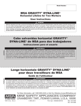
Step 4. Remove the slack from the horizontal lifeline by pulling
the rope through the tensioner by hand. To tension
the horizontal lifeline, use a pointed bar or a 1 1/8 in.
wrench and turn the tensioning nut clockwise until the
tensioner slips. Do not modify the rope tensioner to
achieve greater lifeline tension. See Figure 8. The fi nal
tension will be 300 to 450 lbs. (1.3 to 2.0 kN).
Figure 8 - Tensioning the Horizintal Lifeline
Tensioning the
Horizontal Lifeline
Pointed Bar
Rope Tensioner
Tensioning Nut
Figure 7 - Tie-off Adapter
Installing Tie-Off Adaptor to Vertical
or Sloped Anchorage Structure.
Vertical or Sloped
Anchorage Structure
Tie-Off Adaptor
Wrap Tie-Off Adaptor twice
around Anchorage Structure

15
3.3 OPERATION:
A. PERSONAL FALL ARREST SYSTEM COMPONENTS: Inspect
and don the full body harness according to manufacturer’s
instructions. Attach the connecting subsystem (energy
absorbing lanyard or SRL) to the dorsal connection on the
harness.
B. CONNECTING TO THE HORIZONTAL LIFELINE SYSTEM:
Approach the work area using the appropriate access
equipment. Connect your personal fall arrest system to one of
the attachment O-rings on the horizontal lifeline. Connectors
must meet all compatibility and strength requirements.
C. HAZARDOUS SITUATIONS: Do not take unnecessary risks,
such as jumping or reaching too far from the edge of the
working surface. Do not allow the connecting subsystem
to pass under arms or between feet. To avoid inadequate
clearance, do not climb above the horizontal lifeline. To avoid
swing fall hazards, do not work too far from either side of the
horizontal lifeline.
D. TWO (2) PERSONS CONNECTED TO THE HLL: When a
person falls while connected to the horizontal lifeline, the
system will deflect. If two (2) persons are connected to
the same horizontal lifeline, and one (1) person falls, the
second person may be pulled off the working surface due to
deflection. The potential for the second person falling increases
as the horizontal lifeline span length increases. The use of
independent horizontal lifeline systems for each person, or
shorter span length, is recommended to minimize the potential
of the second person falling.
E. FREE FALL: The personal fall arrest system must be rigged to
limit free falls to 6 feet (1.8m) or less when using an energy
absorbing lanyard, or such that the SRL is overhead without
slack, according to OSHA requirements.
F. SHARP EDGES: Avoid working where the connecting
subsystem or other system components will be in contact with,
or abrade against, unprotected sharp edges. If working around
sharp edges is unavoidable, a protective cover must be used to
prevent cutting of the personal fall arrest system components.
G. IN THE EVENT OF A FALL: The responsible party must have
a rescue plan and the ability to implement a rescue. Tolerable
suspension time in a full body harness is limited, so a prompt
rescue is critical.
H. RESCUE: With the number of potential scenarios for a
worker requiring rescue, an on-site rescue team is beneficial.
The rescue team is given the tools, both in equipment and
technique, to perform a successful rescue. Training should be
provided on a periodic basis to ensure rescuers’ proficiency.

16
Figure 9 - Releasing Tension from the Horizontal Lifeline
Releasing Tension on
the Horizontal Lifeline
Pointed Bar
Locking Lever
Rope Tensioner
Tensioning Nut
3.4 SYSTEM REMOVAL: When no longer required, the horizontal
lifeline system should be removed from the job site.
A. RELEASE TENSION ON THE HORIZONTAL LIFELINE:
Step 1. Lift the locking lever and position the pointed bar under
the locking lever as shown in Figure 9.
Step 2. Push the pointed bar in a upward motion to unlock the
lever.
Step 3. Loosen the tensioning nut by inserting the pointed bar
through the hole in the nut, or use a 1 3/16 in (30 mm)
wrench, and turn the tensioning nut counterclockwise.
Step 4. Remove all knots and kinks in the rope before storage.
4.0 TRAINING
4.1 It is the responsibility of all users of this equipment to understand
these instructions, and to be trained in the correct installation,
use, and maintenance of this equipment. These individuals must
be aware of the consequences of improper installation or use
of this equipment. This user manual is not a substitute for a
comprehensive training program. Training must be provided on a
periodic basis to ensure profi ciency of the users.
5.0 INSPECTION
5.1 INSPECTION FREQUENCY: The Sayfl ine Synthetic Rope
Horizontal Lifeline System shall be inspected by the user before
each use and, additionally, by a competent person
1
other than the
user after installation and at intervals of no more than one year
2
.
Results of the Competent Person inspection should be recorded in
the “Inspection and Maintenance Log” at the back of this manual.
1 Competent Person: One who is capable of identifying existing and predictable hazards in the
surroundings or working conditions which are unsanitary, hazardous, or dangerous to employees, and who
has authorization to take prompt corrective measures to eliminate them.
2 Inspection Frequency: Extreme working conditions (harsh environments, prolonged use, etc.) may
require increasing the frequency of competent person inspections.

17
5.2 INSPECTION STEPS:
Step 1. Inspect all metal components (hooks, O-rings, rope
tensioner, etc.) for cracks, deformities, corrosion,
or other damage that may affect their strength or
operation.
Step 2. Inspect rope for concentrated wear; especially those
portions of the rope that contact the Rope Tensioner.
Material must be free of frayed strands, broken yarns,
cuts, abrasions, burns, and discoloration. The rope
must be free of knots, excessive soiling, paint build-up,
and rust staining. Inspect ferrules for cracks or other
damage. Thimble must be held fi rmly by the ferrule.
Check for chemical or heat damage; indicated by brown,
discolored, or brittle areas. Check for ultraviolet damage;
indicated by discoloration, splinters, and slivers along
the rope surface. All of the above factors are known to
reduce rope strength.
ROPE CORE: Concentrated wear, cuts,
abrasion, or burns may expose the white inner
core of the rope. Any time the white inner core
of the rope is visible, excluding the cut ends
of the rope, the rope shall be removed from
service and no longer used. If the braided
black cover must be pulled, spread apart, or
separated by hand to expose the white core,
the rope is still acceptable for use. Frayed or
broken strands that give the rope a “fuzzy”
appearance are acceptable, provided the white
inner core is not visible.
Acceptable:
White inner core
is not exposed.
Unacceptable:
White inner core
is exposed.
Step 3. Inspect system labels. The labels must be present and
fully legible. See section 8.0.
IMPORTANT: If this equipment is subjected to the forces of a
fall arrest, it must be removed from service and destroyed, or
returned to DBI-SALA for inspection or repair.
5.3 If inspection reveals an unsafe or defective condition, remove unit
from service and destroy, or contact DBI-SALA for possible repair.
IMPORTANT: Only DBI-SALA or parties authorized in writing
may make repairs to this equipment.
5.4 USER EQUIPMENT: Inspect harness and energy absorbing
lanyard or SRL according to manufacturer’s instructions.
5.5 i-Safe™ RFID TAG: If your equipment
has an i-Safe Radio Frequency
Identifi cation (RFID) tag (Figure 10),
the RFID tag can be used with a reading
device to simplify inspection and provide
records for your equipment. Contact
Capital Safety or see the Capital Safety
website (http://www.capitalsafety.com/
en-us/Pages/i-Safe.aspx).
Figure 10 - RFID

18
6.0 MAINTENANCE, SERVICING, STORAGE
6.1 CLEANING AND MAINTENANCE: Clean the horizontal lifeline
system with water and a mild detergent. Wipe dry with a clean,
dry cloth and hang to air dry. Do not force dry with heat. An
excessive build-up of dirt, paint, etc. may prevent the system
from working properly, and in severe cases, weaken the rope. A
lubricant may be applied to the moving parts of the rope tensioner.
Do not allow lubricant to contact the rope tensioner teeth.
6.2 STORAGE: Store this horizontal lifeline system in a clean, dry
environment, out of direct sunlight. Avoid areas where chemical
vapors are present. Thoroughly inspect the system after extended
storage.
6.3 USER EQUIPMENT: Maintain, service, and store user equipment
according to manufacturer’s instructions.
7.0 SPECIFICATIONS
7.1 MATERIALS:
• Rope Tensioner: Steel, plated
• O-rings: Alloy steel, plated
• Lifeline Rope: 11/16 in. nylon, static kernmantle, breaking
strength: 12,000 lb.
• Rope Tensioner Strap: Polyester/Nylon
• Snap Hooks: Alloy steel, plated
• Carabiners: High tensile alloy steel, plated
• Tie-off Adaptor: Polyester web, plated alloy steel hardware

19
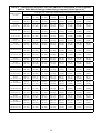
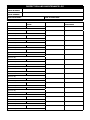
8.0 LABELING
8.1 The following labels must be present and fully legible:
WARNING

INSPECTION AND MAINTENANCE LOG
SERIAL NUMBER:
MODEL NUMBER:
DATE PURCHASED: DATE OF FIRST USE:
INSPECTION DATE INSPECTION ITEMS
NOTED
CORRECTIVE ACTION MAINTENANCE
PERFORMED
Approved By:
Approved By:
Approved By:
Approved By:
Approved By:
Approved By:
Approved By:
Approved By:
Approved By:
Approved By:
Approved By:
Approved By:
Approved By:
Approved By:
Approved By:
Approved By:
Approved By:
Approved By:
Page is loading ...
Page is loading ...
Page is loading ...
Page is loading ...
-
 1
1
-
 2
2
-
 3
3
-
 4
4
-
 5
5
-
 6
6
-
 7
7
-
 8
8
-
 9
9
-
 10
10
-
 11
11
-
 12
12
-
 13
13
-
 14
14
-
 15
15
-
 16
16
-
 17
17
-
 18
18
-
 19
19
-
 20
20
-
 21
21
-
 22
22
-
 23
23
-
 24
24


3M DBI-SALA® Sayfline™ Synthetic Horizontal Lifeline System 7600503, 1 ea Operating instructions
- Type
- Operating instructions
- This manual is also suitable for
-
- DBI-SALA® Sayfline™ Synthetic Horizontal Lifeline System 7600502, 1 ea
- DBI-SALA® Sayfline™ Synthetic Horizontal Lifeline System 7600504, 1 EA
- DBI-SALA® Sayfline™ Synthetic Horizontal Lifeline System 7600505, 1 ea
- DBI-SALA® Sayfline™ Synthetic Horizontal Lifeline System 7600506, 1 EA
- DBI-SALA® Sayfline™ Synthetic Horizontal Lifeline System 7600507, 1 ea
- DBI-SALA® Sayfline™ Synthetic Horizontal Lifeline System 7600508, 1 EA
- DBI-SALA® Sayfline™ Synthetic Horizontal Lifeline System 7600509, 1 ea
- DBI-SALA® Sayfline™ Synthetic Horizontal Lifeline System 7600510, 1 EA
Ask a question and I''ll find the answer in the document
Finding information in a document is now easier with AI
Related papers
-
3M PROTECTA® PRO-Line™ Temporary Horizontal Lifeline System 1200101, EA Operating instructions
-
DBI-SALA 2200401 Operating instructions
-
-
-
-
DBI-SALA DBI-SALA® Cab Mount Self Retracting Lifeline, Web 3101008, 8 ft. (2.4m), 1 EA User manual
-
-
-
-
DBI-SALA DBI-SALA® Twin-Leg Tie-Back Quick Connect Self Retracting Lifeline, Web 3102115, 7.5 ft. (2.3m), 1 EA User manual
Other documents
-
Honeywell Miller MightEvac User Instruction Manual
-
DBI SALA Sayfline 7603160 User Instruction Manual
-
Guardian Quadro (formerly Big Boss) Horizontal Lifeline Operating instructions
-
 SafeWaze 019-8031 Owner's manual
-
Philips Medical Alarms 6900 User manual
-
Miller HLLR Series User manual
-
Extron MR D Series Template
-
Toshiba PX1706E-1HJ0 Datasheet
-
 SafeWaze 019-8025 Owner's manual
-
 Dyna-Line Gravity® Temporary Horizontal Lifelines Owner's manual


