SSV Works RZ5-Q5XARC User manual

Type
User manual

SSV Works RZ5-Q5XARC is an audio kit that will transform your Polaris RZR 5 with Ride Command into a concert on wheels. With a powerful 800-watt amplifier, 5 Kicker speakers, and a 10-inch subwoofer, this kit will deliver an immersive sound experience that will make your rides unforgettable. The included glove box subwoofer enclosure ensures that you'll feel the bass in your bones, while the kick panel and cage mount speakers provide crystal-clear highs and mids. Installation is a breeze with the included instructions and all the necessary hardware.

SSV Works RZ5-Q5XARC is an audio kit that will transform your Polaris RZR 5 with Ride Command into a concert on wheels. With a powerful 800-watt amplifier, 5 Kicker speakers, and a 10-inch subwoofer, this kit will deliver an immersive sound experience that will make your rides unforgettable. The included glove box subwoofer enclosure ensures that you'll feel the bass in your bones, while the kick panel and cage mount speakers provide crystal-clear highs and mids. Installation is a breeze with the included instructions and all the necessary hardware.

SSV WORKS, 201 N. Rice Ave Unit A, Oxnard, CA 93030
www.SSVworks.com | Phone: 818-991-1778 | Fax: 866-293-6751
RZ5-Q5XARC
RZR 5 with Ride Command
SSV Works 5 Speaker Audio Kit
Phase 5
RZR5 2020+
Panels, Dash Disassembly,
and Wiring
Subwoofer
Installation
Amp Tray
Installation
pg 6
pg 11
pg 13
Cage Mount Speakers
Installation
pg 15
Kick Panel Speakers
Installation
pg 14
2
!
Please read and understand these
instructions completely before
installation to avoid possible injury,
or damage to the accessory or vehicle.
WARRANTY INFORMATION:
All SSV Works enclosures are covered by a limited lifetime warranty against defects in
material or workmanship. All SSV Works Electronics are covered by a limited 1 year warranty
against defects in material or workmanship. All Kicker Speakers are covered by a limited 1
year warranty against defects in material or workmanship. All Kicker Ampliers are covered by
a limited 2 year warranty against defects in material or workmanship. Labor for replacement
of defective components is not covered. Contact SSV Works for further warranty information.
Wiring Installation
SSV WORKS, 201 N. Rice Ave Unit A, Oxnard, CA 93030
www.SSVworks.com | Phone: 818-991-1778 | Fax: 866-293-6751
PARTS LIST 1/4
TOOLS NEEDED FOR INSTALLATION
- T25, T30, T40 Torx Driver - 10mm wrench
PARTS LIST IMAGES
2. 800.5 Amp Mounting Plate 3. Amp Power Wire x2
6. M6 x 1.0 Screws and
Washers x4 (T-30 torx)
4. Speaker Expansion Cable x1
7. Fuse Holder with 40A
Fuse x 2
5. B-H219 for Door Pods
1. 800.5 PhaseEQ Amp
3
!
Please read and understand these
instructions completely before
installation to avoid possible injury,
or damage to the accessory or vehicle.
WARRANTY INFORMATION:
All SSV Works enclosures are covered by a limited lifetime warranty against defects in material
or workmanship. All SSV Works Electronics are covered by a limited 1 year warranty against
defects in material or workmanship. All SSV Works Speakers are covered by a limited 1 year
warranty against defects in material or workmanship. All Kicker Speakers are covered by a
limited 1 year warranty against defects in material or workmanship. Labor for replacement of
defective components is not covered. Contact SSV Works for further warranty information.
Glove Box Subwoofer Enclosure
SSV WORKS, 201 N. Rice Ave Unit A, Oxnard, CA 93030
www.SSVworks.com | Phone: 818-991-1778 | Fax: 866-293-6751
PARTS LIST 2/4
TOOLS NEEDED FOR INSTALLATION - Torx Driver T25 T30 T40 - Panel removal tools
PARTS LIST IMAGES
2. Base Bracket
5. M6x1.0x40mm x2 6. M6 washers x11 7. M6 Speed Clips x2
1. RZ5-UD10 Enclosure 4. M6x1.0x12mm x93. Clamp Bracket
4
Kicker 6.5” Speaker Front Kick Panels
WARRANTY INFORMATION:
All SSV Works enclosures are covered by a limited lifetime warranty against defects in
material or workmanship. All SSV Works Electronics are covered by a limited 1 year warranty
against defects in material or workmanship. All Kicker Speakers are covered by a limited 1
year warranty against defects in material or workmanship. All Kicker Ampliers are covered by
a limited 2 year warranty against defects in material or workmanship. Labor for replacement
of defective components is not covered. Contact SSV Works for further warranty information.
SSV WORKS, 201 N. Rice Ave Unit A, Oxnard, CA 93030
www.SSVworks.com | Phone: 818-991-1778 | Fax: 866-293-6751
PARTS LIST 3/4
!
Please read and understand these
instructions completely before
installation to avoid possible injury, or
damage to the accessory or vehicle.
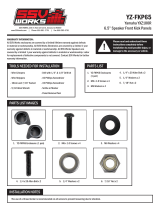
TOOLS NEEDED FOR INSTALLATION
- T25, T30, T40 Torx Driver - 10mm wrench
PARTS LIST IMAGES
2. M6 x 14mm Screws x8
5. Mounting Brackets x2
1. RZ5-DF65 Enclosure (pair) 4. M6 x 16mm Screws &
M6 Nuts x4
3. M6 Washers x16
5
!
Please read and understand these
instructions completely before
installation to avoid possible injury, or
damage to the accessory or vehicle.
WARRANTY INFORMATION:
All SSV Works enclosures are covered by a limited lifetime warranty against defects in
material or workmanship. All SSV Works Electronics are covered by a limited 1 year warranty
against defects in material or workmanship. All Kicker Speakers are covered by a limited 1
year warranty against defects in material or workmanship. All Kicker Ampliers are covered by
a limited 2 year warranty against defects in material or workmanship. Labor for replacement
of defective components is not covered. Contact SSV Works for further warranty information.
TOOLS NEEDED FOR INSTALLATION
- Torx T25, T40 - Wrench 8mm, 10mm
PARTS LIST IMAGES
2. Dual Mounting Clamp Base
x 2
5. M6x1.0x45mm (5mm Allen
Head) Screws & Washers x4
6. M6x1.0x6mm (3mm Allen
Head) Screws x4
10. Zip Tie Panel Post x5 11. Zip Ties
7. B-H2195 Rear Speaker
Harness
8. B-H1912 & B-H1913
Speaker Extension Harness
1. RZ5-C65ARC Enclosures
(1 pair) 4. M6x1.0x20mm (8mm Hex
Head) Screws & Washers x4
3. 2” Ring Clamp x 4
- Socket 10mm
SSV WORKS, 201 N. Rice Ave Unit A, Oxnard, CA 93030
www.SSVworks.com | Phone: 818-991-1778 | Fax: 866-293-6751
- 3mm, 4mm, 5mm Allen Key
PARTS LIST 4/4
Cage Mount
Kicker 6.5” Speaker Enclosures
6
A
PANELS AND DASH DISASSEMBLY
D
B
E
C
A
A. Remove all the seats from the vehicle. Compress the release lever located in front of the seat base. With the release lever compressed, tilt the seat
forward and remove from the vehicle.
D. Remove the (2) T40 torx screws and (2) push pins with a panel
removal tool.
B. Using a 8mm wrench. Disconnect the negative battery cable from
the battery.
E. Open the top-center dash compartment and lift to remove the compartment
tray. We recommend using a panel tool to assist releasing the tray from the
compartment. Once the tray is separated from the compartment, pull out the
USB cable from the tray, set tray to the side.
C. Remove the (2) T40 torx screws and set the hood panel aside.
7
I
K
G
H
J
F. Use a panel tool to assist with the removal of the (3) trim panels. The
blue highlighted points represent the location of the panel clips that are
retaining the trim panels to the dash.
I. Use a panel to aid in lifting the fenders to release the top dash panel.
K. Lift and remove the glove compartment from the dash cavity.
G. Open the glove compartment. Remove the (4) T25 Torx screws and
(3) T40 Torx screws.
H. Remove the (4) T40 Torx screws that surround the gauge cluster. For
ease of access to each screw we recommend adjusting the position
of the steering column accordingly.
J. Pull dash from the vehicle.
F
8
P Q
N
L M
O
P. Remove the (2) push pins that are found on the bottom of the dash
towards the center console.
Q. Loosen the 10mm screw on the left of the fuse block (circled in
blue) and remove the 10mm screw on the right (circled in yellow).
The fuse block is located on the driver side of the center console
near the gas pedal.
N. Disconnect the 12V socket.
L. Open the center console and twist to disengage the locking pins
and lift out the center console tray.
M. Remove the (2) T40 torx screws from both sides of the center console and
lift out the rear portion of the center console.
O. Remove the (1) push pin and (8) T40 screws from each side of the
remainder of the center console.
9
U
W
SR
T
V
U. Gently lift center console to release/separate driver and passenger
console side panels
W. Twist the lock knobs on the rear rewall and remove the rewall.
S. Remove the (2) push pins on the passenger side front of the center
console.
R. Rotate the fuse block counterclockwise and remove the now exposed
push pin.
T. Lift the shift boot to expose the (1) T40 screw for removal
V. With the center console separated, unclip the LED from the driver and
passenger console side panel. Once the LEDs have been unclipped,
remove the driver console side panel from the vehicle.
10
RUNNING WIRING AND CABLES
B
B. Run the power (Pink) and expansion speaker cables (Blue - B-H1913
extension cable) down the center of the vehicle to the rear. Follow
factory wiring harnesses when routing the cable and avoid sharp edges
or rotating vehicle parts.
A
A. Route both of the expansion harnesses down the dash cavity and through the
grommet on the front of the passenger console side panel.
C
C. Route one speaker cable to their assigned speaker door pods
(Yellow - B-H2195). Route the power cable to the battery - Do not
connect the power cable to the battery yet.
11
A A
A. Secure the base bracket to the enclosure with (6) M6x1.0x12mm T30 screws and washers.
SUBWOOFER INSTALLATION
B C
B. Slip on (2) M6 speed clips onto the specied locations of the rewall. C. From the Passenger footwell, lift the RZ5-UD10 into the dash cavity.
D E
D. The top of the enclosure will tuck under the chassis cross bar. The
bottom of the enclosure will rest above this edge of the rewall.
E. Apply force to the bottom of the enclosure to swing it into place.
Once it is in place the lower mounting points will be in-line with the
(2) M6 clip nuts.
12
F F
F. Place the clamp bracket over the chassis and base mounting bracket. Secure the clamp bracket to the base bracket with (3) M6x1.0x12mm
T30 screws and washers.
G
G. Secure the bottom of the enclosure with the provided M6x1.0x40mm
T30 screws and washers to the M6 clip nuts attached to the rewall.
H. Connect the subwoofer cable to the 800.5 amplier output.
H
I1. Place zip-tie through zip-tie post. Press zip-tie post into the zip-tie post holes that follow down the center of the vehicle. Starting from the rear of
the vehicle, zip-tie the speaker cable to the vehicle and zip-tie post that were pressed in down the center of the vehicle in the previous step. Coil
and zip-tie any slack in the harness towards the front of the vehicle.
I1
I1 I1
13
AMP TRAY INSTALLATION - WITH FACTORY RIDE COMMAND (ALL MODELS)
Follow these steps if you currently have the Polaris factory door speakers already installed. This process
will deactivate the factory amp and speakers. If you want to continue to use the factory system with this
audio system, please contact SSV Works at 818-991-1778 x2 or email support@SSVworks.com
Disconnect and
uninstall the factory
amplier. Discard as
it will not be needed
anymore. We always
recommend e-recycling
any unwanted
electronics.
RIDE COMMAND HARNESS
1. Amp Input - B-H2591
2. Amp Output
3. Speaker Out FR2
4. Amp Turn-On
1. INPUT (FRONT)
2. INPUT (REAR)
3. INPUT (SUB)
4. OUTPUT (SUB)
5. B-H2701
6. OUTPUT (FRONT)
7. OUTPUT (REAR)
8. EXT SWITCH
9. AMP TURN-ON
10. TO POWER INPUT
1
2
3
4
5
67
8
9
10
808000.5 AMP.5 AMP800.5 AMP
1
2
3
4
14
AMPLIFIER INSTALLATION
B
C
B. Remove the (5) push pins located on the plastic tray in the dash
cavity.
C. Extract (2) T25 screws located at the back of the plastic tray, once
extracted remove the plastic tray.
D
D. Line up the 800.5 amp plate in the same location.
F. Replace the (2) T25 screws.
F G
G. Connect the INPUT and OUTPUT Harness into
the 800.5 amp. Connect ground wire to billet
connector that the factory amp was plugged
into when it was removed.
E. Replace the (5) push pins.
E
A. Disconnect the factory amp connector, and plug in the provided
16-pin Ride-Command connector
A
15
C. Remove the (11) T40 torx screws and (2) T25 Torx screws from the door and set the door skin aside (Step C1). Put the pod in place on inside of the door.
Loosely fasten (2) T30 M6x1.0x14mm torx screw and washers through the top of the door frame and into the RZ5-DF65 (Step C2 & C3).
B. The mounting brackets are side specic. To verify the correct orientation of the bracket, follow the outline in the diagram above.
C2 C3
B1 B2
DRIVER PASSENGER
TOPTOP TOPTOP
BOTTOMBOTTOM BOTTOMBOTTOM
C1
PODS INSTALL
A. Fasten the mounting brackets to the enclosures with (2) T30 M6x1.0x14mm screws and washers.
A1 A2
DRIVER PASSENGER
TOP TOP
STRAIGHTSTRAIGHT
STRAIGHTSTRAIGHT
ANGLEDANGLED
ANGLEDANGLED
BOTTOM BOTTOM
16
D1 D2
D. Insert (2) T30 M6x1.0x16mm torx screws and washers through the front of the
enclosure mounting bracket and secure to the door frame with (2) 10mm M6 nuts
and washers. Tighten hardware once it has all been installed.
E
E. Route the B-H2195 Driver and passenger cables to their
assigned speaker pods. Connect the B-H2195 to the door
pod cable.
SPEAKER POD INSTALL
C1. Find your desired orientation for the US-C65A on your roll
cage and fasten the set screws with a 3mm allen key in the
opposite holes of where the clamp will install two.
D1. Loosely install the clamp base to the US-C65A with (2)
M6x1.0x20mm screws and washers using a 8mm open-ended
wrench. Position the clamp base to your desired position and
tighten the (2) M6x1.0x20mm screws.
C1 D1
E1. Wrap a plastic bag around the roll cage to prevent scratching. Press the clamps onto the roll cage over the plastic bag. Place the (2) M6x1.0x45mm
screws and washers through the clamp and clamp base. Secure the clamps to the roll cage with a 5mm allen key.
E1 E1 E1
17
CONNECTING POWER & GROUND CABLE TO BATTERY
CB
A2 A3
B. Unscrew the factory nut on the negative battery terminal. Install
the 2 ground cables to the screw on the ground battery terminal.
Re-install the factory nut.
A1. Remove the bottom cover of the fuse holder
by extracting the 2 screws. Break off the right
and left side tabs on the bottom cover.
A2. Extract both fuse holder screws. A3. Attach both the Power Wire and Battery
Terminal Cable to the fuse holder. Reattach
the bottom cover.
C. Unscrew the factory nut on the positive battery terminal. Install the 2
power cables to the screw on the postive battery terminal. Re-install
the factory nut.
Power
Wire
Battery
Terminal
Cable
A1
Break
off tab
Break
off tab
F1. Position the speaker to your liking and tighten the 8mm hex
screws.
F1
18
E
D
E. Zip tie all of the electrical cabling (factory and audio) along the center
column away from the drive shaft.
D. Remove the top of the fuse holder and extract the 2 screws. Insert the
40A fuse, screw the 2 screws back in and reattach the fuse holder top.
THIS CONCLUDES THE INSTALLATION PROCESS.
© 2022 SSV Works, Oxnard, CA 93030 RZ5-Q5XARC 9-27-22
  • Page 1 1
  • Page 2 2
  • Page 3 3
  • Page 4 4
  • Page 5 5
  • Page 6 6
  • Page 7 7
  • Page 8 8
  • Page 9 9
  • Page 10 10
  • Page 11 11
  • Page 12 12
  • Page 13 13
  • Page 14 14
  • Page 15 15
  • Page 16 16
  • Page 17 17
  • Page 18 18

SSV Works RZ5-Q5XARC User manual

Type
User manual

SSV Works RZ5-Q5XARC is an audio kit that will transform your Polaris RZR 5 with Ride Command into a concert on wheels. With a powerful 800-watt amplifier, 5 Kicker speakers, and a 10-inch subwoofer, this kit will deliver an immersive sound experience that will make your rides unforgettable. The included glove box subwoofer enclosure ensures that you'll feel the bass in your bones, while the kick panel and cage mount speakers provide crystal-clear highs and mids. Installation is a breeze with the included instructions and all the necessary hardware.

Ask a question and I''ll find the answer in the document

Finding information in a document is now easier with AI