X32-Q3A3

SSV Works X32-Q3A3 Installation guide

  • Hello! I'm your chat assistant, and I've reviewed the SSV Works user manual for the Phase 3 X32-Q3A3 Audio Kit. This document contains detailed installation instructions for adding a comprehensive audio system to your Can-Am X3, covering everything from panel disassembly and wiring to component mounting. I'm ready to answer your questions about the installation process, the included parts, and the features of your new audio system
  • What vehicles is this audio kit designed for?
    What components are included in this kit?
    Is there a warranty on the SSV Works enclosures?
    What tools are needed for installation?
1
SSV WORKS, 201 N. Rice Ave Unit A, Oxnard, CA 93030
www.SSVworks.com | Phone: 818-991-1778 | Fax: 866-293-6751
X32-Q3A3
Can-Am X3
SSV Works 3 Speaker Audio Kit
Phase 3
Panels, Dash Disassembly,
and Wiring
Amp Tray
Installation
Underseat Subwoofer
Installation
pg 6
pg 9
pg 14
Kick Panel Speakers
Installation
pg 17
MRB3 and Dash Kit
Installation
pg 12
Can-Am X3 2014+
2
!
Please read and understand these
instructions completely before
installation to avoid possible injury, or
damage to the accessory or vehicle.
WARRANTY INFORMATION:
All SSV Works enclosures are covered by a limited lifetime warranty against defects in
material or workmanship. All SSV Works Electronics are covered by a limited 1 year warranty
against defects in material or workmanship. All SSV Works Speakers are covered by a
limited 1 year warranty against defects in material or workmanship. Labor for replacement of
defective components is not covered. Contact SSV Works for further warranty information.
TOOLS NEEDED FOR INSTALLATION
- T30 torx
- 10mm wrench or ratchet
- 13mm wrench or ratchet
- 18 mm socket with extention
- Wire crimpers
- Panel removal tool
PARTS LIST IMAGES
- #2 screw driver
- #3 screw driver
SSV WORKS, 201 N. Rice Ave Unit A, Oxnard, CA 93030
www.SSVworks.com | Phone: 818-991-1778 | Fax: 866-293-6751
2. B-H1909 Front
Speaker Harness
7. M6 x 16mm Screw x 2 8. M6 Washer x 3
9. M6 Locking Hex Nut 10. Zip Ties x 5 11. Fuse Holder with 40A Fuse x2 12. Battery Terminal Cable x2
1. Amp Power Wire x2
5. Amp Tray with pre-loaded
PhaseEQ Amp and MRB3 brain
4. MRB3 Power & Ground
Connector
Wiring Installation
PARTS LIST 1/4
6. M6 Flange Hex Head Bolt
3. B-H1912 & B-H1913
Rear Speaker Expansion x 2
3
SSV WORKS, 201 N. Rice Ave Unit A, Oxnard, CA 93030
www.SSVworks.com | Phone: 818-991-1778 | Fax: 866-293-6751
!
Please read and understand these
instructions completely before
installation to avoid possible injury, or
damage to the accessory or vehicle.
WARRANTY INFORMATION:
All SSV Works enclosures are covered by a limited lifetime warranty against defects in
material or workmanship. All SSV Works Electronics are covered by a limited 1 year warranty
against defects in material or workmanship. All Kicker Speakers are covered by a limited 1
year warranty against defects in material or workmanship. All Kicker Ampliers are covered by
a limited 2 year warranty against defects in material or workmanship. Labor for replacement
of defective components is not covered. Contact SSV Works for further warranty information.
1. X3-DM3 Base Plate
2. X3-DM3 Top Panel
3. #7 x 1.25 Kit Screws x4
TOOLS NEEDED FOR INSTALLATION PARTS LIST
PARTS LIST IMAGES
4. M3 x 20mm Screws x2
5. M3 Washers x 2
6. M3 Hex Nuts x 2
2. X3-DM3 Top Panel
1. X3-DM3 Base Plate
- #2 Phillips Screw Driver
- 1/8” drill bit
- 1/2” drill bit
- Drill
INSTALLATION NOTES
For instructions regarding the MRB3 black box, refer to the MRB3 manual.
5. M3 Washers x 2
4. M3 x 20mm Screws x2 6. M3 Hex Nuts x 2
3. #7 x 1.25 Kit Screws x4
Dash Kit
PARTS LIST 2/4
4
!
Please read and understand these
instructions completely before
installation to avoid possible injury, or
damage to the accessory or vehicle.
WARRANTY INFORMATION:
All SSV Works enclosures are covered by a limited lifetime warranty against defects in material
or workmanship. All SSV Works Electronics are covered by a limited 1 year warranty against
defects in material or workmanship. All Kicker Speakers are covered by a limited 1 year
warranty against defects in material or workmanship. All Kicker Ampliers are covered by a
limited 2 year warranty against defects in material or workmanship. Labor for replacement of
defective components is not covered. Contact SSV Works for further warranty information.
TOOLS NEEDED FOR INSTALLATION
2. M6 x 16mm Screws &
Washers x 10 (T-30 torx)
7. A-Bracket x 1
11. M6 Locking Hex Nut
8. Large Bracket
12. Foam Strips x 5
3. Thread Rolling Screw x 2 4. M6 x 25mm Screw x 1
5. Large washers x 2
9. Seat Spacer x 1
1. X32-DUS10 Enclosure
6. C-Bracket
10. Small Spacer x 1
- 10mm, 13mm, 16mm and
18mm Sockets & Wrenches
- T-30 & T-40
Torx Driver
- 1½” Hole Saw - Hole Punch /
Scribe Tool
- Ratchet & Extension - #3 Phillips
Screwdriver
Triangular
end
SSV WORKS, 201 N. Rice Ave Unit A, Oxnard, CA 93030
www.SSVworks.com | Phone: 818-991-1778 | Fax: 866-293-6751
PARTS LIST IMAGES
Under Seat Subwoofer Enclosure
PARTS LIST 3/4
5
SSV WORKS, 201 N. Rice Ave Unit A, Oxnard, CA 93030
www.SSVworks.com | Phone: 818-991-1778 | Fax: 866-293-6751
!
Please read and understand these
instructions completely before
installation to avoid possible injury, or
damage to the accessory or vehicle.
WARRANTY INFORMATION:
All SSV Works enclosures are covered by a limited lifetime warranty against
defects in material or workmanship. All SSV Works Electronics are covered by a
limited 1 year warranty against defects in material or workmanship. All SSV Works
Speakers are covered by a limited 1 year warranty against defects in material or
workmanship. Labor for replacement of defective components is not covered.
Contact SSV Works for further warranty information.
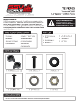
1. X3-F65 Enclosures (1 pair)
2. M6 x 1.0 Screws x 6
3. M6 Washers x 6
4. M5 screws and washers 8
TOOLS NEEDED FOR INSTALLATION PARTS LIST
PARTS LIST IMAGES
5. Large Bracket x 2
6. Small Bracket x 2
7. Driver Side Template
8. Passenger Side Template
2. M6 x 1.0 Screws x 6
6. Small Bracket x 2 7. Driver Side Template 8. Passenger Side Template
1. X3-F65 Enclosures
(1 pair)
5. Large Bracket x 2
3. M6 Washers x 6 4. M5 Screws and
Washers x 8
- T-30 Torx Driver
- Drill with 1/4” Drill bit
- Scribe or Punch tool
- Phillips / at head
screwdriver
- 10 mm wrench
X3-F65 KICKPOD DRILL TEMPLATE - DRIVER SIDE
DRIVER SIDE
X3-F65 KICKPOD DRILL TEMPLATE - PASSENGER SIDE
PASSENGER SIDE
SPEAKER
WIRE
SSV Works 6.5” Speaker Front Kick Panels
PARTS LIST 4/4
6
A
PANELS AND DASH DISASSEMBLY
B B B
A
C
A. To remove the seat, use a 13mm socket and wrench to remove front (2) bolt and nut, and use a 18mm socket to remove (2) rear nuts and seat belt nut
( repeat on other seat)
B. Carefully unsnap console panels by hand or with a panel removal tool.
C. Unscrew (2) T30 torx located on the center console panel under the
dash. Use a panel tool to remove push pins on passenger side.
D
D. Carefully unsnap rear cover to expose the engine compartment
7
EE E
E. Remove gas cover on the passenger side to expose a 10mm nut. Unscrew with a wrench and T30 torx driver.
F
F. Remove fender well panel using a T30 driver (will need a10mm socket for
the screw near the headlight)
G
G. After the fender well panel is removed, remove the third fastener clip
from the bottom.
E2E2 E2
E2. Using panel removal tool unsnap (2) push clips on the driver and passenger side dash covers. Unscrew the (4) T30 screws on the passenger
side, and (7) T30 screws on the driver side.
8
RUNNING AMP POWER CABLE AND SPEAKER WIRE
A1 A2
A. In this step you will be feeding all of the necessary wires from the top drivers side dash down the center dash column. Be sure to run all of the wires
along side the factory cabling to avoid any moving parts. Feed both amp power wires, both audio expansion harness, (one is for subwoofer, the second
is for rear speakers sold separately), and power/ground for MRB3 from top driver side down the center column (A1). Pull all wires through the bottom
center column and across the center console with the factory wiring (A2).
B. Run the second audio expansion harness through rear center console cavity,
following the factory cables. The harness will be use for Cage Mounted
Speakers sold separately.
B
9
B
A. From underneath driver side place amp plate between the two cross bars behind the steering wheel.
(MRB3 Brain attached, inclusion will depend on kit.)
A
AMP PLATE INSTALLATION
1. INPUT (FRONT) - CONNECT TO MRB3 “FRONT SPEAKERS”
2. INPUT (REAR) - CONNECT TO MRB3 “REAR SPEAKERS”
3. INPUT (SUB) - CONNECT TO MRB3 “LINE OUT EXT AMP TRIGGER
4. OUTPUT (SUB) - CONNECT TO SUB
5. B-H2701
6. OUTPUT (FRONT) - CONNECT TO FRONT SPEAKER HARNESS
7. OUTPUT (REAR) - CONNECT TO REAR SPEAKER EXPANSION
8. EXT SWITCH
9. AMP TURN-ON
10. TO POWER INPUT
808000.5 AMP.5 AMP800.5 AMP
1
2
3
4
5
67
8
9
10
10
H
H. Connect the front (white/gray) and rear (green/purple) outputs from
the MRB3 power harness to the inputs of the 800.5 amp.
D
F
C
D. Make a pilot hole with a pick tool through the top right screw hole
in the amp plate and push all the way through the vehicle panel.
F. Drill larger holes through the pilot holes using a 1/4” drill bit.
Be sure to move the amp plate out of the way before drilling.
C. Secure the amp tray to the vehicle using the supplied M6 ange hex
head Bolt, 10mm nut and washer.
G
G. Repeat Step C and then use the included M6 x 16mm Screws and
washers in your drilled holes to secure the amp plate .
E
E. Make a pilot hole with a pick tool through the bottom screw hole in
the amp plate and push all the way through the vehicle panel.
11
J. Connect the front (white/gray) and rear (green/purple) inputs of the 800.5 amplier. Connect the audio extension harness to the output of
800.5 amplier (J1). Connect amplier power harnesses to amplier (J2).
J2J1
K K K
K. Connect the MRB3 power harness to the power strip located on the passenger side of the center console. Unscrew the top post, remove the nut and
install the black-ground wire terminal. Replace the nut. Unscrew the center post, remove the nut and install the red-battery power wire terminal. Replace
the nut.
I1 I2
I. Route the front speaker harness (B-H1909) towards the driver and passenger side of the vehicle and leave the 4 pin connector at the driver
side of dash (I1). Route the passenger side speaker wire under the center dash panel all the way to the passenger side speaker location (I2).
12
DASH KIT
A
D
C C C
B
E
A. Remove the factory rocker switches.
D. Place the base plate back on the dash lining up the outside
screw holes to the dimples on the dash. Using (2) #7 Screws and
a philips screw driver secure the base to the dash. Make sure the
screws are driving into the dash dimples for best results.
Line up base plate Drill pilot hole Drill 1/2” hole
C. Rest the X3-DM3 base plate on the dash. Line up the two outside screw holes with the dimples of the dash. Do not screw the kit in yet.
While holding the base plate down to the dash, use the center hole on the base plate to drill your 1/8” pilot hole.
Remove the base plate and open the pilot hole up using a 1/2” drill bit.
B. Locate the two dimples at the top of the dash. These dimples
are actual screw bosses on the underside of the dash.
E. Fasten the MRB3 Remote to the dash kit using (2) M3 screws.
13
G
H
G
G. Using (2) #7 screws, secure the top of the Top Panel to the Base Plate.
H. Refer to the MRB3 manual for wiring instructions.
F. Now that the MRB3 remote is mounted to the dash kit route the din cable through the base plate so that it drops into the dash. Plug
into wire control panel. Make sure arrows align. Push carefully until you hear a click.
Pull the din cable all the way through until the X3-DM3 Top Panel rests on the Base Plate.
F F F
14
A. Apply the short foam strips to the large bracket in the order shown above (A1).
Apply the long foam strips to the outside edges of the enclosure. (Driver outside = left /
Passenger outside = right) (A2).
B. Using the supplied T-30 torx M6 screws and washers, screw the
C bracket to the bottom left side of the enclosure.
C. Using the supplied T-30 torx M6 screws and washers, screw the
Large bracket to the right side of the enclosure shown above. Do
not screw in all the way, leave the screws somewhat loose so that
you can t the enclosure snug and then tighten the screws after.
A2A1
B C
D D
D. To remove driver the seat, use a 13mm socket and wrench to remove front (2) bolt and nut, and use a 18mm socket to remove (2) rear nuts and
(1) 16mm seat belt bolt. Disconnect the seat belt sensor.
UNDER SEAT SUBWOOFER ENCLOSURE
15
G. Replace the factory seat bolt spacer with the supplied SSV
Works spacer on top of bracket C.
F. Remove the seat mounting spacer from the seat mounting stud
towards the center of the car.
Feed the enclosure down under the seat bar and simultaneously
guide “Bracket C” over the inner seat mounting stud that does
not have the spacer. The Factory spacer will not be re-used***
As the enclosure is set into place, the brake line is to run along
the dedicated channel on the sub enclosure. Make any routing
adjustments to the brake line so the enclosure lays down at without
any tension on the brake line. Bracket C should be sitting at on top
of the oor plastic once the enclosure is in place.
FG
H. Place bracket A to the right side of the enclosure (H1). Line up the 2 screw holes and proceed to hand thread the T-30 torx screws and washers. Use a T-30
torx bit to tighten screws (H2). Line up the top of bracket A hole on the factory seat brakcet. Screw in the T-30 torx screw with the large washer (H3).
H1 H2 H3
E. Remove the factory 10mm nut and bolt from the brake line. Place the washer on top of the factory bracket and push the long M6x25mm screw through
the top. Then attach the brake line, spacer, washer and nut. (Disregard this step for the 4-seat Maverick X3 Max)
E E E
16
J. Route the rst audio extension harness out from the center console away from any moving parts and sharp metal then connect to the
X32-DUS10.
J J
THIS STEP IS OPTIONAL
H. To help minimize skid plate rattle, we have supplied a drill template that adds 4 holes to help relieve air pressure that is being generated by the high
output of the sub enclosure. Remove sub enclosure and leave brackets in place, and line up the template under the sub mounting brackets (H1). With
hole punch/scribe tool mark the 4 drilling points through the template on to the oorboard (H2). Drill the four (4) - 1½” holes with a hole saw (H3).
Some x3 models have a thinner skid plate that
others and may rattle more. We have provided a
drill template to help minimize skid plate rattle.
H1 H2 H3
DRILL TEMPLATE
I. The large bracket will align over (2) factory holes in the chassis.
Using a #3 Phillips screwdriver, secure the large bracket to the
chassis with the provided (2) thread rolling screws and washers.
I
17
D. Remove gas tube from fender and place back on gas tank
until install is complete
B2 B3
D
NOTE: Steps C-D are for the Passenger side only
A. Front covers will need to be removed, start by removing
passenger side gas cover.
B. Remove the eleven (11) T30 Torx bolts that secure the fender.
Note: There is three (3) T30 screws on passenger side and
two (2) on driver side that will have a 10mm bolt. Remove the
metal clip that is securing the top panel to the fender.
C. Using a at head screw driver to loosen the hose clamp on the
gas tube.
Note: You will have to remove three (3) additional T30 screws
holding the top OE speaker pod cover for access to gas clamp.
A B1
C
B4
FRONT KICK PANELS
18
G. Using a 1/4” drill bit, drill holes for mounting the pod. Use
a 1/2” drill bit to drill the hole for routing the speaker cable
connector.
I. Place the smaller bracket on top of the bar and line up the
holes with the large bracket. Using the M5 screws, tighten
both brackets to one another (make sure the drilled out holes
line up to brackets)
G
I
F. Using a scribing tool, mark the center of the three (3) drill points
illustrated on the template as shown in image F.
H. Place the larger bracket on inside of the cage tube.
J. Route speaker connector through the 1/2” hole that was
drilled out.
E. Cut out the template (Driver/Passenger) along the cut line.
Position the template on inner plastic ,making sure to square
up the template along the factory panel as shown in image E.
F
H
J
E
Pod holesPod holes
Cable holeCable hole
19
M. Make your speaker connection Installation is complete. Repeat for driver side pod.
M
K. Place the kick pod in position for mounting. Use the provided
M6 screws and washers to hand tighten the pod to the kick
panel.
L. Once all screws have been inserted into pod , tighten all three
(3) screws.
K L
20
;).,&.32''5,//7(03/$7('5,9(56,'(
%3*7&34*%&
/