
GB
Technical
Manual
GA 24
Model 544907
4132280

Copyright 2003 Textron Inc. “All rights reserved, including the
right to reproduce this material or portions thereof in any form.”
To Order Parts
1. Write your full name and complete address on the
order.
2. Explain where and how to make shipment.
3. Give product number, name and serial number that is
stamped on the name plate or serial plate of your prod-
uct.
4. Order by the quantity desired, the part number, paint
code, and description of the part as given in the parts
list.
5. Send or bring the order to an authorized Textron Turf
Care And Specialty Products Dealer.
6. Inspect all shipments on receipt. If any parts are dam-
aged or missing, file a claim with the carrier before
accepting.
7. Do not return material without a letter of explanation,
listing the parts being returned. Transportation charges
must be prepaid.
Use of other than authorized parts will void the warranty.
Proposition 65 Warning
Engine exhaust from this product
contains chemicals known to the State
of California to cause cancer, birth
defects, and other reproductive harm
Table of Contents
1 Safety
1.1 Operating Safety................................................. 4
1.2 Important Safety Notes .......................................5
2 Specifications
2.1 Product Identification .......................................... 6
2.2 Engine .................................................................6
2.3 Aerator ................................................................6
2.4 Tractor ................................................................7
2.5 Weights and Dimensions ....................................7
2.6 Accessories & Support Literature .......................7
3 Decals and Icons
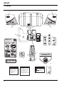
3.1 Decals................................................................. 8
3.2 Icons ...................................................................8
4 Controls
4.1 Control Descriptions ...........................................9
5 Operation
5.1 Daily InspectioN................................................ 11
5.2 Operator Presence Control (OPC) ....................11
5.3 Operating Procedures .......................................12
5.4 Starting .............................................................12
5.5 Stopping / Parking ............................................13
5.6 To Drive / Transport ..........................................13
5.7 Hillside Operation .............................................13
5.8 Aerating ............................................................14
5.9 Trailering ...........................................................14
6 Adjustments
6.1 General ............................................................ 15
6.2 Turf Guard ........................................................15
6.3 Aerator Drive Idler Cable ..................................15
6.4 Traction Drive Idler Cable ................................16
6.5 Aerator Timing ..................................................16
6.6 Shift Control Cable ...........................................17
6.7 Lift Cable ..........................................................17
6.8 Torque Specification ........................................18
7 Maintenance
7.1 General ............................................................ 19
7.2 Engine ..............................................................19
7.3 Engine Oil .........................................................20
7.4 Engine Air Filter ................................................20
7.5 Fuel ..................................................................20
7.6 Hydraulic Hoses ...............................................21
7.7 Hydraulic Oil .....................................................21
7.8 Muffler and Exhaust .........................................22
7.9 Tires .................................................................22
7.10 Wheel Mounting Procedure ..............................22
7.11 Care and Cleaning ...........................................22
7.12 Storage .............................................................23
8 Troubleshooting
8.1 General ............................................................ 24
9 Maintenance & Lubrication Charts
9.1 General ............................................................ 25
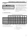
9.2 Maintenance Charts .........................................25
10 Notes
11 Parts Catalog
11.1 Table Of Contents............................................ 27
Litho in U.S.A. 3-2004

3
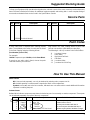
Suggested Stocking Guide
To Keep your Equipment fully operational and productive, maintain a stock of the more commonly used maintenance
items. We have included part numbers for additional support materials and training aids. A more complete listing of
accessories and attachments can be found in the Specifications Section
How To Use This Manual
Abbreviations
N/S - Not serviced seperately, can only be obtained by ordering main component or kit.
AR -Variable quantity or measurement is required to obtain correct adjustment.
Symbols such as ▲, next to the item number, indicate that a note exists which contain additional information
important in ordering that part.
Indented Items
Bulleted items indicate component parts that are included as part of an assembly or another component. These parts
can be ordered separetely or as part of the main component.
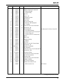
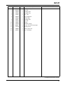
Item Part No. Qty Description Serial Numbers/Notes
▲ 1 123456 1 Mount, Valve Indicates a piece part
2 789012 1 Valve, Lift Includes Items 2 and 3
3 345678 1 • Handle Serviced part included with Item 2
4 N/S 1 • Seal Kit Non serviced part included with Item 2
5 901234.6 1 Screw, 1/4-20 x 2” Hex Head Indicates a part painted Jacobsen Orange
Service Parts
Paint Codes
A paint code suffix is required when ordering painted
parts. The available paint codes for each part are listed
in the Parts Catalog using the following format:
[Part Number].[Paint Code]
For example:
123456.7 represents part 123456 painted Gloss Black.
If more than one paint code is listed, choose the paint
code that matches your machine.
Parts listed in the Parts Catalog without a paint code
suffix do not need the suffix added to order parts.
The following is a list of Jacobsen Paint Code Suffixes
.6 Jacobsen Orange
.7 Gloss Black
.8 High Heat Flat Black
.9 Flat Black
.10 Jacobsen White
.11 Jacobsen Non Skid Gray
Qty. Part No. Description Qty. Part No. Description
4132280 Technical Manual

1 SAFETY
4
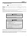
1 SAFETY
1.1 OPERATING SAFETY ______________________________________________________
1. Safety is dependent upon the awareness, concern
and prudence of those who operate or service the
equipment. Never allow minors to operate any
equipment.
2. It is your responsibility to read this manual and all
publications associated with this equipment (Engine
Manual, accessories and attachments). If the
operator can not read English it is the owner’s
responsibility to explain the material contained in
this manual to them.
3. Learn the proper use of the machine, the location
and purpose of all the controls and gauges before
you operate the equipment. Working with unfamiliar
equipment can lead to accidents.
4. Never allow anyone to operate or service the
machine or its attachments without proper training
and instructions; or while under the influence of
alcohol or drugs.
5. Wear all the necessary protective clothing and
personal safety devices to protect your head, eyes,
ears hands and feet. Operate the machine only in
daylight or in good artificial light.
6. Inspect the area where the equipment will be used.
Pick up all the debris you can find before operating.
Beware of overhead obstructions (low tree limbs,
electrical wires, etc.) and also underground
obstacles (sprinklers, pipes, tree roots, etc.) Enter a
new area cautiously. Do not enter narrow openings
that may force operator too close to unit. Stay alert
for hidden hazards.
7. Never direct discharge of material toward
bystanders, nor allow anyone near the machine
while in operation. The owner/operator can prevent
and is responsible for injuries inflicted to
themselves, to bystanders and damage to property.
8. Never operate equipment that is not in perfect
working order or is without decals, guards, shields,
discharge deflectors or other protective devices
securely fastened in place.
9. Carbon monoxide in the exhaust fumes can be fatal
when inhaled. Never operate the engine without
proper ventilation.
10. Fuel is highly flammable, handle with care.
11. Keep the engine clean. Allow the engine to cool
before storing and always remove the ignition key.
12. Disengage all drives and engage parking brake
before starting the engine (motor).
13. Equipment must comply with the latest federal,
state, and local requirements when driven or
transported on public roads.
14. Never use your hands to search for oil leaks.
Hydraulic fluid under pressure can penetrate the
skin and cause serious injury.
15. Operate the machine up and down the face of the
slopes (vertically), not across the face (horizontally).
16. To prevent tipping or loss of control, do not start or
stop suddenly; reduce speed when making sharp
turns. Use caution when changing direction on
slopes.
This machine is to be operated and maintained as specified in this manual and is intended for the professional
maintenance of specialized turf grasses. It is not intended for use on rough terrain or long grasses.
WARNING
EQUIPMENT OPERATED IMPROPERLY OR BY UNTRAINED PERSONNEL CAN BE DANGEROUS.
Familiarize yourself with the location and proper use of all controls. Inexperienced operator’s should receive
instruction from someone familiar with the equipment before being allowed to operate the machine.
!

SAFETY 1
5
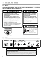
1.2 IMPORTANT SAFETY NOTES ________________________________________________
This safety alert symbol is used to alert you to potential hazards.
DANGER - Indicates an imminently hazardous situation which, if not avoided, WILL result in death or serious injury.
WARNING - Indicates a potentially hazardous situation which, if not avoided, COULD result in death or serious
injury.
CAUTION - Indicates a potentially hazardous situation which, if not avoided, MAY result in minor or moderate injury
and property damage. It may also be used to alert against unsafe practices.
For pictoral clarity, some illustrations in this manual may show shields, guards or plates open or removed. Under no
circumstances should this equipment be operated without these devices securely fastened in place
By following all instructions in this manual, you will prolong the life of your machine and maintain its maximum
efficiency. Adjustments and maintenance should always be performed by a qualified technician.
If additional information or service is needed, contact your Authorized Jacobsen Dealer who is kept informed of the
latest methods to service this equipment and can provide prompt and efficient service. Use of other than original or
authorized Jacobsen parts and Accessories will void the warranty.
WARNING
The Operator Presence Control (OPC) on this machine will shut off the
aerator and traction drive if the operator releases the OPC handle.
To protect the operator and others from injury, never operate equipment with
the OPC system disconnected or malfunctioning.
!
!
WARNING
1. Before leaving the operator’s position for any reason:
a. Release OPC handle.
b. Lower aerator head to the ground.
c. Stop engine
d. Disconnect spark plug wire.
2. Keep hands, feet, and clothing away from moving parts. Wait for all
movement to stop before you clean, adjust or service the machine.
3. Keep the area of operation clear of all bystanders and pets.
4. Never carry passengers.
5. Never operate mowing equipment without the discharge deflector
securely fastened in place.
!

2 SPECIFICATIONS
6
2 SPECIFICATIONS
2.1 PRODUCT IDENTIFICATION_________________________________________________
544907............................GA 24 Aerator with OPC, 8 hp
gasoline engine.
Serial Number ................An identification plate, like the one
shown, listing the serial number, is
attached to the right side frame,
near the engine.
Always provide the serial number of the unit when ordering
replacement parts or requesting service information.
2.2 ENGINE__________________________________________________________________
Make...............................Briggs & Stratton
Model..............................Intek Pro OHV
Horsepower ....................8 hp (6.0 kW) @3600 rpm
Displacement..................18.64 cu. In. (305.4 cc)
Bore x Stroke..................2.94 x 2.75 in (74.61 x 69.85 mm)
Fuel:
Type..........................Unleaded Gasoline
Rating .......................Min. 85 Octane
Capacity.................... 2.5 U.S. Gal. (9.5 liters)
Governor......................... Flyweight Mechanical
Lubrication:
Capacity.................... 1 quart (0.95 liters)
Type.......................... SAE 30W
API Classification ..... SG, SH, SJ
Air Filter.......................... Replaceable Dual Element.
Cooling System .............. Air Cooled
2.3 AERATOR________________________________________________________________
Spacing...........................2 in. (51 mm) on center
Depth of Penetration.......3 in. (76 mm) maximum
Standard Tines
Type..........................Hollow, Tapered
Material.....................Case Hardened Steel
Quantity .................... Two sets 1/2 in. (13 mm)
diameter
Tine Options
Solid..........................1/4 in. (6 mm) Quad Tines
Hollow.......................1/4 in. (6 mm), 3/8 in. (9 mm), 5/8
in. (16 mm)
Swath Width....................24 in. (609 mm)
CHARLOTTE, NC MADE IN U.S.A.
®
A Textron Company
544907 1601

SPECIFICATIONS 2
7
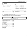
2.4 TRACTOR ________________________________________________________________
Tires
Front..........................11 x 4.00 - 5 2 Ply
Rear..........................16 x 6.50 - 6 4 Ply
Pressure:...................14 psi (97 kPa)
Speed:
H (Transport) ...........0 - 4.0 mph (6.4 kph)
L (Aerate).................. 0 - 0.9 mph (1.4 kph)
R (Reverse) .............. 0 - 1.8 mph (2.9 kph)
Hydraulic System:
Capacity.................... 2 U.S. gal. (7.57 liters)
Fluid Type.................GreensCare 68
Aerator Head Lift.......Hydraulic Double Acting Cylinders
2.5 WEIGHTS AND DIMENSIONS ________________________________________________
Dimensions: Inches (mm)
Length............................................................. 72 (1676)
Width............................................................ 49.5 (1257)
Height.............................................................. 48 (1219)
Weights: Lbs. (kg)
Working Weight Less Fuel............................ 850 (386)
2.6 ACCESSORIES & SUPPORT LITERATURE _____________________________________
Contact your area Jacobsen Dealer for a complete listing of accessories and attachments.
Accessories
Air Blow Gun...........................................................JAC5098
Orange Touch-up Paint (12 oz. spray)...................... 554598
Coring Quad Tine Accessory.................................. 4116987
Solid Quad Tine Accessory..................................... 4116986
Tines (12 Required)
1/4 in. (6 mm) Coring ................................................ 517486
1/4 in. (6 mm) Solid................................................... 523863
3/8 in. (9 mm) Coring ................................................ 517487
1/2 in. (13 mm) Coring.............................................. 517488
1/2 in. (13 mm) Heavy Duty Coring........................... 523995
1/2 in. (13 mm) Carbide Tipped Coring..................... 547183
5/8 in. (16 mm) Coring.............................................. 517489
Support Literature
Technical Manual.................................................... 4132280
Operator Training Video.......................................... 4130949
CAUTION
Use of other than Jacobsen authorized parts and accessories may cause personal injury or damage to the
equipment and will void the warranty
!

3 DECALS AND ICONS
8
3 DECALS AND ICONS
3.1 DECALS _________________________________________________________________
Familiarize yourself with the decals they are critical to the safe operation of the machine.
REPLACE DAMAGED DECALS IMMEDIATELY.
3.2 ICONS ___________________________________________________________________
WARNING
Never attempt to drive the tractor unless you have read the Technical Manual and know
how to operate all controls correctly.
Familiarize yourself with the icons shown above and what they represent. Learn the
location and purpose of all the controls and gauges before operating this tractor.
KEEP HANDS AND FEET AWAY
DANGER
835892
340623
1. Leer el manual del operador. No permitir que personas
no capacitadas para ello usen la maquina.
2. Mantener los escudos en su lugar y la tornilleria
debidamente fijada.
3. Antes de limpiar, ajustar o reparar este equipo,
desengranar todas los mandos, aplicar el freno de
estacionamiento y apagar el motor.
4. Mantener las manos, los pies y la ropa alejados de las
piezas en movimiento.
5. No viajar como pasajero ni llevar pasajeros en
maquinas sin asiento para ello.
6. Mantener a las demas personas alejadas.
7. Si no sabe leer ingles, solictarle a otra persona que le
lea y explique el contenido de las etiquetas y del
manual de le maquina.
! ADVERTENCIA
361854
1. Read operator’s manual. Do not allow
untrained operators to use machine.
2. Keep shields in place and hardware
securely fastened.
3. Before you clean, adjust or repair this
equipment, disengage all drives, engage
parking brake and stop engine.
4. Keep hands, feet and clothing away from
moving parts.
5. Never carry passengers.
6. Keep bystanders away.
! WARNING
524729
Exposed moving parts
can cause severe injury.
Do not operate without
covers in place.
See Operators /
Maintenance manual.
! WARNING
Read Manual Engine Throttle
Fast Choke Slow
Fuel
Tine Lever
Lift Lower
OPC
Release
Tine
Engage
!

CONTROLS 4
9
4 CONTROLS
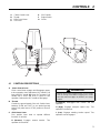
4.1 CONTROL DESCRIPTIONS __________________________________________________
A. Clutch Control Lever
Clutch control lever engages and disengages power
to tine operation clutch and latches OPC handle.
Pull
lever until OPC handle (E) closes for Transport. Pull
handle until it clicks and locks in place for tine
operation. Release the OPC handle to disengage.
B. Throttle
Controls the ground speed of the unit. Position lever
between SLOW and FAST to set desired ground
speed. Fully raise lever to STOP position to shut off
engine.
C. Shift Control Lever
Four position lever used to operate different
functions of machine.
R (Reverse): Engages reverse traction. Tine
operation is locked out.
N (Neutral): Disengages both traction and tine
operation.
H (High): Engages transport speed only. Tine
operation is locked out.
L (Low): Engages aerating traction speed. Tine
operation can be engaged
A
L
H
N
R
C
D
B
E
F
G
A Clutch Control Lever
B Throttle
C Shift Control Lever
D Tine Lever
E OPC Handle
F Engine Switch
G Choke
WARNING
Damage to turf and/or equipment may occur if aerator
head is not fully raised before engaging OPC handle
with shift control lever (C) in R (Reverse) or H (High)
position.
!

4 CONTROLS
10
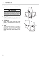
D. Tine Lever
Raises and lowers aerator head. Lift lever to RAISE
position to raise head. Push lever to LOWER position
to lower head.
E. OPC Handle
Engages and disengages drive clutch. Returns clutch
control lever (A) to disengaged position when
released.
F. Engine Switch
Controls engine operation. Move switch to ON
position for normal operation. Move switch to OFF
position to shut unit off or when adjusting, trailering
or storing unit.
G. Choke
The choke lever opens and closes the choke valve in
the carburetor. The CLOSED position enriches the
fuel mixture for starting a cold engine. The OPEN
position provides the correct fuel mixture for
operation after starting, and for restarting a warm
engine.
WARNING
To prevent injury from hot hydraulic oil, the tine lever
must be returned to the neutral position after raising or
lowering the unit. If the lever sticks or is held in the
“RAISE” or “LOWER” position, the hydraulic fluid will
overheat, possibly causing a hydraulic line to rupture
!
A
L
H
N
R
C
D
B
E
F
G

OPERATION 5
11
5 OPERATION
5.1 DAILY INSPECTION ________________________________________________________
1. Perform a visual inspection of the entire unit, look for
signs of wear, loose hardware, and missing or
damaged components. Check for fuel or oil leaks to
ensure connections are tight and hoses and tubes
are in good condition.
2. Check the hydraulic oil level, fuel supply, crankcase
oil and air cleaner. All fluids must be at the full level
mark with engine cold.
3. Check tires for proper inflation.
5.2 OPERATOR PRESENCE CONTROL (OPC) _____________________________________
1. The OPC system is intended to protect the operator
and others from injury by stopping the aerator and
drive mechanism as soon as the operator releases
the OPC handle.
2. Test OPC system.
a. Start the engine and place throttle (B) at slow.
Fully raise aerator head.
b. Place shift control (C) in R (Reverse) position. In
this position, unit will move away from operator
when testing.
c. Pull clutch control lever (A) slightly until OPC
handle (E) can be engaed. Do not engage tine
operation.
d. The drive mechanism will engage and the unit
will slowly move backward.
e. Release the OPC handle. The handle must come
up and the wheels must stop. Shut off engine.
f. Place shift control (C) in L (Low) position.
g. Pull clutch control lever (A) slightly until OPC
handle (E) can be engaed. Engage tine
operation.
h. Release the OPC handle (E). The clutch control
lever (A) must return to disengaged position, and
OPC handle must come up.
i. Check each position of shift control lever (C).
Tine operation should only engage with lever in L
(Low) position.
3. If the wheels begin to turn before the OPC handle is
engaged or the wheels continue to turn after the
OPC handle is released, or clutch control lever does
not return to disengaged position; stop the engine
immediately and have the system repaired.
CAUTION
The daily inspection should be performed only when
the engine is off and all fluids are cold. Lower aerator
head to the ground, stop engine and disconnect spark
plug wire.
!
WARNING
Never operate equipment with the OPC system
disconnected or malfunctioning.
!

5 OPERATION
12
5.3 OPERATING PROCEDURES_________________________________________________
1. Before starting engine, always release OPC handle.
2. Do not operate aerator or attachments with loose,
damaged or missing components.
3. First aerate in a test area to become thoroughly
familiar with the operation of the unit and control
levers.
4. Study the area to determine the best and safest
operating procedure. Consider the type of terrain,
and condition of the surface. Each condition will
require certain adjustments or precautions.
5. Never direct discharge of material toward
bystanders, nor allow anyone near the machine
while in operation. The owner/operator is
responsible for injuries inflicted to bystanders and/or
damage to their property.
6. Use discretion when operating near gravel areas
(roadway, parking areas, cart paths, etc.). Stones
struck by the unit may cause serious injuries to
bystanders and/or damage the equipment.
7. Always raise aerator head and move control lever
out of L position when not aerating.
8. Disengage the tines and raise the aerator head
when crossing paths or roadways. Look out for
traffic.
9. Stop and inspect the equipment for damage
immediately after striking an obstruction or if the
machine begins to vibrate abnormally. Have the
equipment repaired before resuming operation.
10. Slow down and use extra care on hillsides. Read
Section 5.7. Use caution when operating near drop
offs.
11. Use care when approaching blind corners, shrubs,
tress or other objects that may obscure vision.
12. Never use your hands to clean aerator. Tine edges
are sharp and can cause serious injuries.
5.4 STARTING _______________________________________________________________
1. Check engine crankcase oil levels.
2. Fill fuel tank with fresh, clean unleaded fuel.
3. Turn engine switch to ON position.
4. Place shift control lever (C) in neutral, and
disengage clutch control (A).
5. Move throttle lever (B) to 1/2 throttle.
6. Pull recoil starter located on right side of engine.
Choke as required to start engine.
7. Allow the engine to become warm and properly
lubricated before operating at high RPM.
Figure 5A
CAUTION
To prevent injury, always wear safety glasses, leather work shoes or boots, a hard hat, and ear protection.
!
CAUTION
Before operating, pick up all debris such as rocks,
toys and wire which can be thrown by the machine.
Enter a new area cautiously. Always operate at
speeds that allow you to have complete control of the
unit.
!
WARNING
Before you clean, adjust, or repair this
equipment, always disengage all drives, lower
aerator head to the ground, stop engine and
disconnect spark plug wire to prevent injuries.
!
A
L
H
N
R
C
D
B
E

OPERATION 5
13
5.5 STOPPING / PARKING______________________________________________________
To stop:
Release OPC handle to bring unit to a complete stop.
To park the tractor under normal conditions:
1. Release OPC handle, raise the aerator head. Move
shift control lever to H position, engage OPC handle
and move away from the area of operation.
2. Select a flat and level area to park.
a. Release OPC handle to bring unit to a complete
stop.
b. Lower aerator head to the ground, reduce throttle
to slow and allow engine to operate at no load for
several minutes.
3. Move engine switch to OFF position.
If an emergency arises and the unit must be parked in the
area of operation, follow the guidelines outlined by the
grounds superintendent. If the unit is parked on an
incline, chock or block the wheels.
5.6 TO DRIVE / TRANSPORT____________________________________________________
Read and follow all safety notes contained in this manual
when driving or transporting tractor. Refer to Section 5.3
for general operating instructions. When operating in
reverse look behind you to ensure you have a clear path.
1. Release OPC handle and raise aerator head.
2. Set throttle lever to slow.
3. Move shift control lever to H position and engage
OPC handle to drive to and from the area of
operation.
4. Adjust throttle lever to desired transport speed.
5.7 HILLSIDE OPERATION _____________________________________________________
The unit has been designed for good traction and stability
under normal conditions; however, use caution when
operating on slopes, especially over rough terrain or
when the grass is wet. Wet grass reduces traction and
steering control.
1. Always operate at reduced forward speed to
maintain the control.
2. If the tractor tends to slide or the tires begin to
“mark” the turf, angle tractor into a less steep grade
until traction is regained or tire marking stops.
3. If tractor continues to slide or mark the turf, the
grade is too steep for safe operation. Do not make
another attempt to climb, back down slowly.
Correct tire pressure is essential for maximum traction.
Front 14 psi (97 kPa)
Rear 14 psi (97 kPa)
CAUTION
When transporting, operate unit in such a manner to
allow you to see the path ahead and quickly move
away from the unit should you accidentally lose
control.
!
WARNING
To minimize the possibility of overturning, the safest
method for operating on hills and terraces is to travel
up and down the face of the slope (vertically), not
across the face (horizontally). Avoid unnecessary
turns, travel at reduced speeds, stay alert for hidden
hazards, and drop offs.
CAUTION
Do not operate on slopes greater than 20°.
!
!

5 OPERATION
14
5.8 AERATING _______________________________________________________________
To Aerate:
1. Start the engine raise aerator head.
2. Move shift control lever to L position.
3. Move throttle lever to SLOW, stand to the side of
unit and slowly engage OPC handle.
a. Adjust throttle to desired walking speed after unit
is in motion.
b. Pull clutch control lever until it clicks and locks in
tine operation position.
c. At proper starting point on turf, fully lower aerator
head by pushing down on the tine lever.
4. To stop aerating, pull up on the tine lever to raise
aerator head. Disengage OPC handle.
5.9 TRAILERING _____________________________________________________________
If the unit experiences problems and must be shut down
and removed from the area, it should be loaded onto a
trailer for transport.
Use care when loading and unloading unit. Tines may
drag or catch on trailer ramp. To prevent push rods from
being bent, remove the two lowest positioned tines.
Fasten unit to trailer to prevent tractor from rolling or
shifting during transport.
Long Distance Trailering / Transport. If the unit is to be
trailered on the highway, before strapping to trailer,
inflate tires to:
Front - 22 psi (152 kPa)
Rear - 22 psi (152 kPa)
After unloading tractor, reduce tire pressure to normal
operating pressure. See Section 5.7
WARNING
To prevent serious injuries, keep hands, feet and
clothing away from aerator mechanism.
NEVER use your hands to clean aerator. Tine edges
can be sharp and could cause injuries.
To clear obstructions from tine, disengage master
clutch, raise aerator head, stop engine and disconnect
spark plug wire, then remove obstruction.
!

ADJUSTMENTS 6
15
6 ADJUSTMENTS
6.1 GENERAL ________________________________________________________________
1. Adjustments and maintenance should always be
performed by a qualified technician. If proper
adjustment cannot be made, contact an authorized
Jacobsen Dealer.
2. Replace, do not adjust, worn or damaged
components.
3. Long hair, jewelry or loose fitting clothing may get
tangled in moving parts. Remove jewelry, tuck in
loose fitting clothing and tuck long hair under a cap.
4. Do not change governor settings or overspeed the
engine.
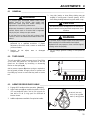
6.2 TURF GUARD _____________________________________________________________
The turf guard (C) is used to prevent the turf from lifting
up as cores are pulled out. The pressure on the turf
guard can be adjusted by increasing or decreasing
tension on the springs (A).
Add or remove spacers (B) above spring as required so
the turf guard provides enough presure to prevent turf
from lifting up, but not so much that they mark or cut the
turf.
Figure 6A
6.3 AERATOR DRIVE IDLER CABLE _____________________________________________
1. Engage OPC handle and tine operation. [ See 4.1]
2. Adjust cable nuts (D) as required to obtain 0.18 inch
(3.3 mm) deflection with a 4.4 lb (2.0 kg) push for
new belt or 3.0 lb (1.4 kg) push for used belt at
location shown.
3. Addition adjustment available if required at handle.
Figure 6B
WARNING
To prevent injury, disengage master clutch, lower
aerator head to the ground, stop engine and
disconnect spark plug wire before making any
adjustments or performing maintenance.
Make sure the aerator is parked on a solid and level
surface. Never work on a tractor that is supported
only by the jack. Always use jack stands.
If only the front or rear of the unit is raised, place
chocks in front of and behind the wheels that are not
raised.
!
CAUTION
Be careful to prevent entrapment of the hands and
fingers between moving and fixed components of the
machine.
WARNING
To prevent injury, support upper frame with blocks
when working on unit with aerator head raised.
Hydraulic lines may rupture or lever could be tripped,
causing unit to drop rapidly.
!
!
A
B
D
0.18 inch (3.3 mm)
4.4 lb (1.81 kg) New
3.0 lb (1.36 kg) Used

6 ADJUSTMENTS
16
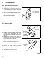
6.4 TRACTION DRIVE IDLER CABLE_____________________________________________
1. Engage OPC handle. [ See 4.1]
2. Adjust cable nuts (E) as required to obtain 0.18 inch
(3.3 mm) deflection with a 4.4 lb (2.0 kg) push for
new belt or 3.0 lb (1.4 kg) push for used belt at
location shown.
3. Addition adjustment available if required at handle.
4. Test handle operation. When OPC handle is
engaged, parking brake (F) should release and idler
pulley should engage traction drive.
Figure 6C
6.5 AERATOR TIMING _________________________________________________________
Note: Improper timing between the aerator crankshaft
and the camshaft will cause elongated holes while
aerating and excessive noise in the camcase.
1. Remove shields from both sides of unit.
2. Remove aerator chain connecting crankshaft to
camshaft from both sides of unit.
3. Loosen stud between crankshaft halves.
4. Rotate right camshaft sprocket (G) until the keyway
is pointing towards the front of the unit. Timing
marks should be at a 45° angle with dot towards the
lower front.
5. Rotate right side crankshaft sprocket (H) until the
timing marks are horizontal with the dot towards the
front. Keyway should be at a 45° angle.
6. Install right side aerator chain (J). Crankshaft
sprocket may be rotated up to 5° in a clockwise
direction only to properly mesh with the chain.
7. Rotate left crankshaft sprocket (K) until the timing
marks are vertical and dot is towards the ground.
8. Install left side aerator chain (L). Crankshaft
sprocket may be rotated up to 5° in a counter-
clockwise direction only to properly mesh with the
chain.
9. Tighten stud between crankshaft halves.
10. Install shields
Figure 6D
Figure 6E
E
F
0.18 inch (3.3 mm)
4.4 lb (1.81 kg) New
3.0 lb (1.36 kg) Used
Timing Marks
Horizontal
Timing Marks
45° Angle
Dot towards
lower front
Dot towards
front
Front
Right Side Aerator Chain
G
H
J
Left Side Aerator Chain
Front
Timing Marks
Vertical
Dot towards
ground
K
L

ADJUSTMENTS 6
17
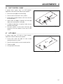
6.6 SHIFT CONTROL CABLE ___________________________________________________
If traction drive system does not shift properly,
adjustment of the shift control cable may be required.
1. Disconnect clevis (N) from shift lever (P).
2. Place the shift control lever in the L position.
3. Rotate shift lever (P) clockwise until it locks into the
low speed detent.
4. Adjust cable nuts (M) as required until clevis (N)
aligns with mounting hole in lever (P).
5. If additional adjustment is required, cable may be
adjusted at the handle.
6. Test each position of shift control. Shift lever (P)
should lock into each detent at each stop of shift
control.
Figure 6F
6.7 LIFT CABLE ______________________________________________________________
If aerator head does not raise or lower properly,
adjustment of the lift cable may be required.
1. Loosen both cable nuts (R). Lift valve should
automaticaly return to center.
2. Place lift control handle in center (neutral) position.
3. Tighten nuts (R).
4. Test operation of lift control.
Figure 6G
M
N
P
R

6 ADJUSTMENTS
18
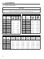
6.8 TORQUE SPECIFICATION __________________________________________________
Jacobsen uses Grade 5 bolts as standard, unless otherwise noted.
CAUTION
All torque values included in these charts are approximate and are for reference only. Use of these torque values is
at your sole risk. Jacobsen is not responsible for any loss, claim, or damage arising from the use of these charts.
Extreme caution should always be used when using any torque value.
AMERICAN NATIONAL STANDARD FASTENERS
SIZE UNITS GRADE 5 GRADE 8
#6-32 in-lbs (Nm) 20 (2.3) –
#8-32 in-lbs (Nm) 24 (2.7) 30 (3.4)
#10-24 in-lbs (Nm) 35 (4.0) 45 (5.1)
#10-32 in-lbs (Nm) 40 (4.5) 50 (5.7)
#12-24 in-lbs (Nm) 50 (5.7) 65 (7.3)
1/4-20 in-lbs (Nm) 95 (10.7) 125 (14.1)
1/4-28 in-lbs (Nm) 95 (10.7) 150 (17.0)
5/16-18 in-lbs (Nm) 200 (22.6) 270 (30.5)
5/16-24 in-lbs (Nm) 240 (27.1) 300 (33.9)
3/8-16 ft-lbs (Nm) 30 (40.7) 40 (54.2)
3/8-24 ft-lbs (Nm) 35 (47.5) 45 (61.0)
7/16-14 ft-lbs (Nm) 50 (67.8) 65 (88.1)
7/16-20 ft-lbs (Nm) 55 (74.6) 70 (94.9)
1/2-13 ft-lbs (Nm) 75 (101.7) 100 (135.6)
1/2-20 ft-lbs (Nm) 85 (115.3) 110 (149.2)
9/16-12 ft-lbs (Nm) 105 (142.4) 135 (183.1)
9/16-18 ft-lbs (Nm) 115 (155.9) 150 (203.4)
5/8-11 ft-lbs (Nm) 150 (203.4) 195 (264.4)
5/8-18 ft-lbs (Nm) 160 (217.0) 210 (284.8)
3/4-10 ft-lbs (Nm) 170 (230.5) 220 (298.3)
3/4-16 ft-lbs (Nm) 175 (237.3) 225 (305.1)
7/8-14 ft-lbs (Nm) 300 (406.8) 400 (542.4)
AMERICAN NATIONAL STANDARD FASTENERS
SIZE UNITS GRADE 5 GRADE 8
METRIC FASTENERS
SIZE UNITS
Non Critical
Fasteners into
Aluminum
M4 Nm (in-lbs) 1.2 (11) 1.7 (15) 2.9 (26) 4.1 (36) 5.0 (44) 2.0 (18)
M5 Nm (in-lbs) 2.5 (22) 3.2 (28) 5.8 (51) 8.1 (72) 9.7 (86) 4.0 (35)
M6 Nm (in-lbs) 4.3 (38) 5.7 (50) 9.9 (88) 14.0 (124) 16.5 (146) 6.8 (60)
M8 Nm (in-lbs) 10.5 (93) 13.6 (120) 24.4 (216) 33.9 (300) 40.7 (360) 17.0 (150)
M10 Nm (ft-lbs) 21.7 (16) 27.1 (20) 47.5 (35) 66.4 (49) 81.4 (60) 33.9 (25)
M12 Nm (ft-lbs) 36.6 (27) 47.5 (35) 82.7 (61) 116.6 (86) 139.7 (103) 61.0 (45)
M14 Nm (ft-lbs) 58.3 (43) 76.4 (55) 131.5 (97) 184.4 (136) 219.7 (162) 94.9 (70)
4.8 5.8 8.8 10.9 12.9

MAINTENANCE 7
19
7 MAINTENANCE
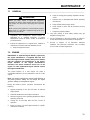
7.1 GENERAL ________________________________________________________________
1. Adjustment and maintenance should always be
performed by a qualified technician. If proper
adjustments cannot be made, contact an Authorized
Jacobsen Dealer.
2. Inspect the equipment on a regular basis, establish a
maintenance schedule and keep detailed records.
a. Keep the equipment clean.
b. Keep all moving parts properly adjusted and lubri-
cated.
c. Replace worn or damaged parts before operating
the machine.
d. Keep all fluids at their proper levels.
e. Keep shields in place and all hardware securely
fastened.
f. Keep tires properly inflated.
3. Long hair, jewelry or loose fitting clothing may get
tangled in moving parts.
4. Use the illustrations in the Parts Catalog as reference
for the disassembly and reassembly of components.
5. Recycle or dispose of all hazardous materials
(batteries, fuel, lubricants, anti-freeze, etc.) according
to local, state or federal regulations.
7.2 ENGINE _________________________________________________________________
IMPORTANT: A separate Engine Manual, prepared by
the engine manufacturer, is supplied with this unit.
Read the engine manual carefully until you are familiar
with the operation and maintenance of the engine.
Proper attention to the engine manufacturer’s
directions will assure maximum service life of the
engine. To order replacement engine manuals contact
the engine manufacturer.
The proper break-in of a new engine can make a
considerable difference to the performance and life of the
engine.
Note: The aerator is designed to operate most efficiently at
the preset governor setting. Do not change the engine
governor settings or overspeed the engine.
During the break-in period, Jacobsen recommends the
following:
1. Operate modestly for the first 25 hours at reduced
engine speed.
2. Avoid full throttle starts and rapid acceleration.
3. Allow the engine to reach operating temperature before
operating at full load.
4. Change the oil and filter after the first 5 hours of
operation.
5. Refer to Section 9.2 and Engine Manual for specific
maintenance intervals.
WARNING
Before you clean, adjust, or repair this equipment,
disengage all drives, lower aerator head to the ground,
stop engine and disconnect spark plug wire to prevent
injuries
Make sure the unit is parked on a solid and level surface.
Never work on a unit that is supported only by the jack.
Always use jack stands.
!

7 MAINTENANCE
20
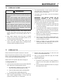
7.3 ENGINE OIL ______________________________________________________________
Check the engine oil at the start of each day, before starting
the engine. If the oil level is low, remove oil filler cap and add
oil as required.
Perform initial oil change after the first 5 hours of operation.
Change oil every 25 hours thereafter.
See the engine manufacturer’s Owners’s Manual for
detailed service information.
After adding or changing oil, start and run engine at idle with
all drives disengaged for 30 seconds. Shut engine off. Wait
30 seconds and check oil level. Add oil to bring up to FULL
mark on dipstick.
Use only engine oils with API classification SG, SH or SJ.
Figure 7A
7.4 ENGINE AIR FILTER _______________________________________________________
1. Remove and service the foam pre-cleaner every 25
hours. Replace if dirty or damaged.
To service pre-cleaner, wash in a liquid detergent and
warm water. Rinse Thoroughly and squeeze dry in a
clean cloth. Saturate in clean engine oil and squeeze
out excess oil in a clean, absorbent cloth.
2. Replace the paper air cleaner element every 100
hours, more often when operating in dusty conditions.
Note: Always replace the paper element. Do not wash
or use pressurized air to clean cartridge.
See the engine manufacturer’s Owners’s Manual for
detailed service information.
7.5 FUEL ____________________________________________________________________
Handle fuel with care - it is highly flammable. Use an
approved container, the spout must fit inside the fuel filler
neck. Avoid using cans and funnels to transfer fuel.
• Fill the fuel tank to within 1 in. (25 mm) of the bottom of
the filler neck.
• Store fuel according to local, state or federal ordinances
and recommendations from your fuel supplier.
• Never overfill fuel tank.
Gas Engine:
• Use clean, fresh, regular grade, unleaded gasoline
minimum 85 Octane.
• Do not use hi-test gasoline or an oil-gasoline mixture.
When using blended fuel, do not use a blend with more
than 10% ethanol. Under no circumstances should you
use a blend with methanol.
Above 32° F (0° C) SAE 30W
Below 32° F (0° C) SAE 5W20 or SAE 5W30
Operating
Range
FULL
mark
WARNING
Never remove the fuel cap from the fuel tank, or add fuel,
when the engine is running or while the engine is hot.
Do not smoke when handling fuel. Never fill or drain the
fuel tank indoors.
Do not spill fuel and clean spilled fuel immediately.
Never handle or store fuel containers near an open flame
or any device that may create sparks and ignite the fuel
or fuel vapors.
Be sure to reinstall and tighten fuel cap securely.
!
Page is loading ...
Page is loading ...
Page is loading ...
Page is loading ...
Page is loading ...
Page is loading ...
Page is loading ...
Page is loading ...
Page is loading ...
Page is loading ...
Page is loading ...
Page is loading ...
Page is loading ...
Page is loading ...
Page is loading ...
Page is loading ...
Page is loading ...
Page is loading ...
Page is loading ...
Page is loading ...
Page is loading ...
Page is loading ...
Page is loading ...
Page is loading ...
Page is loading ...
Page is loading ...
Page is loading ...
Page is loading ...
Page is loading ...
Page is loading ...
Page is loading ...
Page is loading ...
Page is loading ...
Page is loading ...
Page is loading ...
Page is loading ...
Page is loading ...
Page is loading ...
Page is loading ...
Page is loading ...
-
 1
1
-
 2
2
-
 3
3
-
 4
4
-
 5
5
-
 6
6
-
 7
7
-
 8
8
-
 9
9
-
 10
10
-
 11
11
-
 12
12
-
 13
13
-
 14
14
-
 15
15
-
 16
16
-
 17
17
-
 18
18
-
 19
19
-
 20
20
-
 21
21
-
 22
22
-
 23
23
-
 24
24
-
 25
25
-
 26
26
-
 27
27
-
 28
28
-
 29
29
-
 30
30
-
 31
31
-
 32
32
-
 33
33
-
 34
34
-
 35
35
-
 36
36
-
 37
37
-
 38
38
-
 39
39
-
 40
40
-
 41
41
-
 42
42
-
 43
43
-
 44
44
-
 45
45
-
 46
46
-
 47
47
-
 48
48
-
 49
49
-
 50
50
-
 51
51
-
 52
52
-
 53
53
-
 54
54
-
 55
55
-
 56
56
-
 57
57
-
 58
58
-
 59
59
-
 60
60


Ask a question and I''ll find the answer in the document
Finding information in a document is now easier with AI
Related papers
-
Ransomes 58230 User manual
-
-
-
 ryan 544872 User manual
-
-
-
-
-
-

Other documents
-
Toro 21in Walk-Behind Aerator User manual
-
-
-
-
-
Toro 30in Stand-On Aerator User manual
-
-
-
-