Page is loading ...
+)2
+)2
2*
2*
Kichler
®
Lighting
7711 East Pleasant Valley Road
P.O. Box 318010
Cleveland, Ohio 44131-8010
Customer Service
866.558.5706
8:30 AM to 5:00 PM EST,
Monday - Friday
Instruction Manual
Monarch II Patio
TM
A Kichler
®
Select
™
ceiling fan
1. To reduce the risk of electric shock, insure
electricity has been turned off at the circuit
breaker or fuse box before beginning.
2. All wiring must be in accordance with the
National Electrical Code and local
electrical codes. Electrical installation
should be performed by a qualified
licensed electrician.
3. WARNING: Suitable for use with solid-
state speed controls.
4. WARNING: To reduce the risk of personal
injury, use only the two steel screws (and
lock washers) provided with the outlet box
for mounting to the outlet box. Most outlet
boxes commonly used for the support of
lighting fixtures are not acceptable for fan
support and may need to be replaced,
consult a qualified electrician if in doubt.
5. The outlet box and support structure must
be securely mounted and capable of
reliably supporting a minimum of 50
pounds. Use only CUL Listed outlet boxes
marked "FOR FAN SUPPORT".
6. The fan must be mounted with a minimum
of 7 feet clearance from the trailing edge of
the blades to the floor.
7. To operate the reverse function on this
fan, press the reverse button while the fan
is running.
8. WARNING: Use only with light kit marked
"Suitable for Use in Wet Locations".
9. Avoid placing objects in the path of the
blades.
10. To avoid personal injury or damage to the
fan and other items, be cautious when
working around or cleaning the fan.
11. Do not use water or detergents when
cleaning the fan or fan blades. A dry dust
cloth or lightly dampened cloth will be
suitable for most cleaning.
12. After making the electrical connections,
spliced conductors should be turned
upward and pushed carefully up into
outlet box. The wires should be spread
apart with the ground wire and white
(common) wire to one side with the black
(load) wire to the other side of the outlet
box.
13. Electrical diagrams are reference only.
Light kits that are not packed with the fan
must be CUL Listed and marked suitable
for use with the model fan you are
installing. Switches must be CUL General
Use Switches. Refer to the Instructions
packaged with the light kits and switches
for proper assembly.
WARNING
TO REDUCE THE RISK OF FIRE, ELECTRIC
SHOCK OR PERSONAL INJURY, MOUNT
FAN TO OUTLET BOX MARKED
"ACCEPTABLE FOR FAN SUPPORT".
WARNING
TO REDUCE THE RISK OF PERSONAL
INJURY, DO NOT BEND THE BLADE
BRACKETS (ALSO REFERRED TO AS
FLANGES) DURING ASSEMBLY OR AFTER
INSTALLATION. DO NOT INSERT OBJECTS
IN THE PATH OF THE BLADES.
1
1. SAFETY RULES

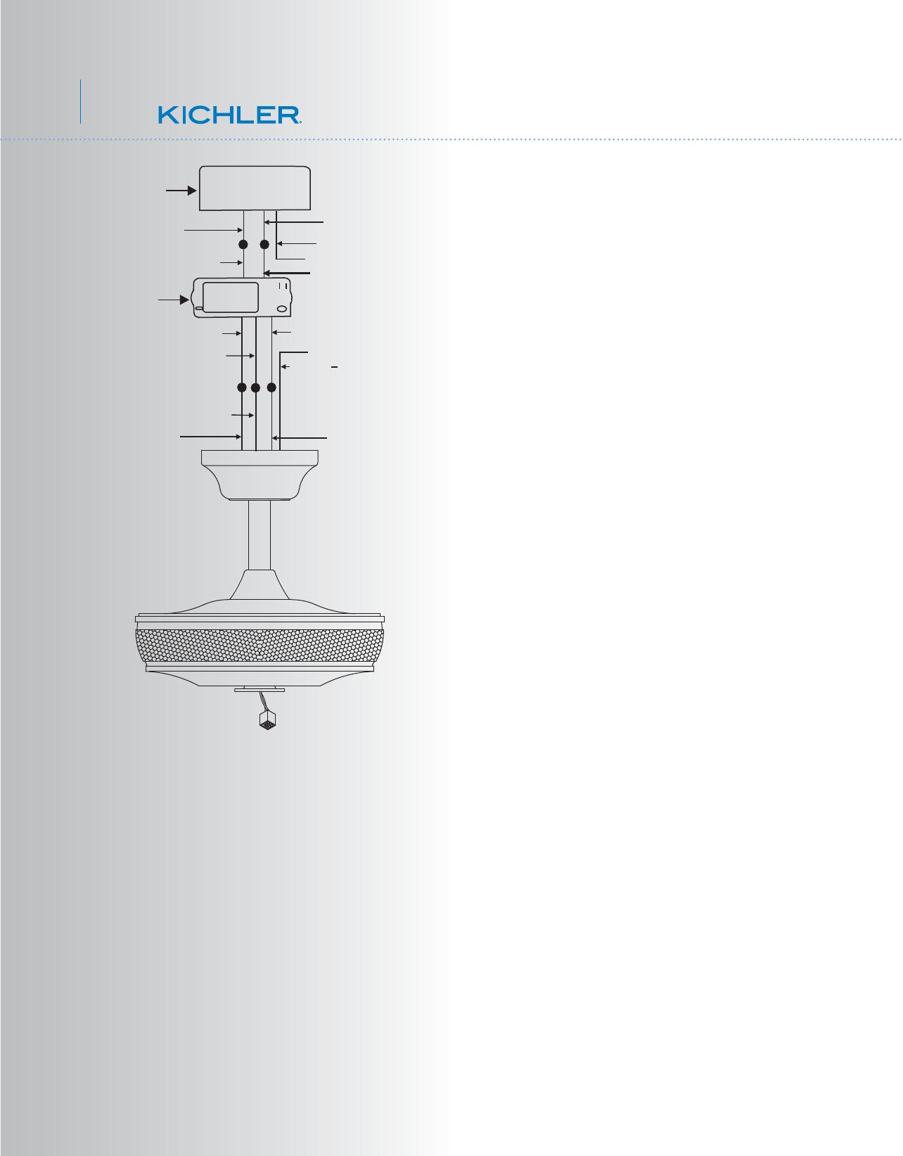
2
3. PACKAGE CONTENTS
Unpack your fan and check the contents. You
should have the following items:
a. Fan blades (5)
b. Canopy & Ceiling mounting bracket
c. Ball/downrod assembly
d. Coupling cover
e. Fan motor assembly
f. Set of 5 blade brackets and Pre-Installed
mounting screws
g. Switch house mounting plate
h. Switch housing
i. Receiver
j. Limited Function CoolTouch™ Control
System
k. Part bag contents
1) Mounting hardware:
star washers (2), wire nuts (3),
machine screws (2), washers (2),
screws (2)
2) Blade attachment hardware:
Screws (17), rubber washers (17)
3) Blade brackets hardware:
screws (2)
4) Safety cable hardware:
wood screw, lock washer, flat washer
5) Balance Kit
Philips screw driver
Blade screw driver
11 mm wrench
Step ladder
Wire cutters
2. TOOLS AND MATERIALS REQUIRED
a
b
c
d
e
f
g
h
k
i
j
Monarch II
TM
Patio
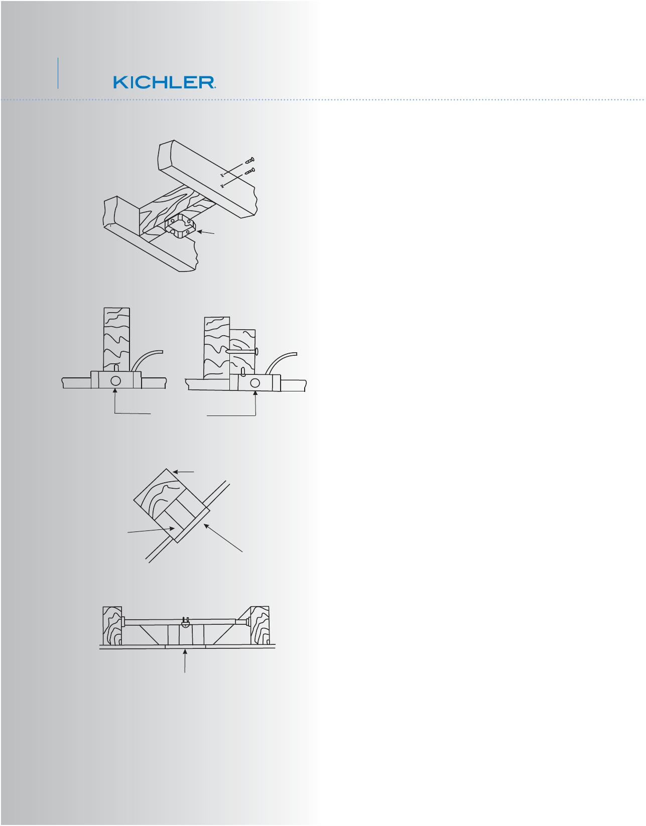
4. MOUNTING OPTIONS
Outlet box
Provide strong
support
Recessed
outlet box
Ceiling
mounting
plate
Outlet box
Fig. 1
Fig. 3
Fig. 4
Outlet box
Fig. 2
ANGLED CEILING
MAXIMUM 30
°
ANGLE
3
If there isn't an existing UL (cUL for Canadian
Installation) listed mounting box, then read the
following instructions. Disconnect the power
by removing fuses or turning off circuit
breakers.
Secure the outlet box directly to the building
structure. Use appropriate fasteners and
building materials. The outlet box and its
support must be able to fully support the
moving weight of the fan (at least 50 lbs). Do
not use plastic outlet boxes.
Figures 1, 2 and 3 are examples of different
ways to mount the outlet box.
NOTE: If you are installing the ceiling fan on a
sloped (vaulted) ceiling, you may need a
longer downrod to maintain proper clearance
between the tip of the blade and the ceiling.
A minimum clearance of 12" is suggested for
optimal operation.
NOTE: Depending on the location you have
selected for installation, you may need to
purchase and install a "Joist Hanger" for the
support of the outlet box. Make sure the joist
hanger you purchase has been designed for
use with ceiling fans. (Fig. 4)

4
Fig. 7
Fig. 8
Mounting screws
(supplied with
electrical box)
Hook
Ceiling
mounting
bracket
UL Listed
outlet box
120V Wires
Washers
Downrod
Cross pin
Hanger
ball
Set screw
Fig. 6
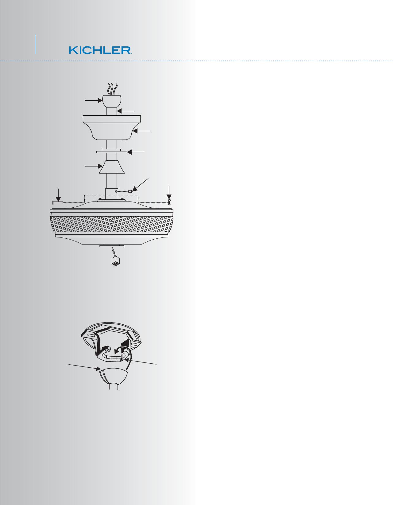
5. HANGING THE FAN
Supply wires
Downrod
Hitch pin
Retaining clip
Coupling
Set screws
Set screws
REMEMBER to turn off the power before you
begin.
To properly install your ceiling fan, follow the
steps below.
Step 1. Remove the decorative canopy
bottom cover from the canopy by turning the
cover counter clockwise. (Fig. 5)
Step 2. Remove the ceiling mounting bracket
from the canopy by removing (and save) one
of the two screws. Loosen the remaining
screw by a half turn. (Fig. 5)
Step 3. Pass the 120 volt supply wires from
the ceiling outlet box through the center of the
ceiling mounting bracket. (Fig.6)
Step 4. Attach the ceiling mounting bracket to
the outlet box using the screws and washers
included with the outlet box. (Fig. 6)
Step 5. Remove the hanger ball from the
downrod assembly by loosening the set
screw, removing the cross pin and sliding the
ball off the rod. (Fig.7)
Step 6. Loosen the two set screws and
remove the hitch pin and retaining clip from
the coupling on top of the motor assembly.
(Fig. 8)
Step 7. Carefully feed the electrical lead wires
from the fan up through the downrod. Thread
the downrod into the coupling until the Hitch
pin holes are aligned.
Next, replace the hitch pin and retaining clip.
Tighten both set screws. (Fig. 8)
Fig. 5
Ceiling mounting
bracket
Canopy
Canopy
cover
Monarch II
TM
Patio
5
Fig. 9
Fig. 10
Registration slot
Check tab
Hanger ball
Canopy
Downrod
Canopy cover
Set screws
Coupling cover
Step 8. Slip the coupling cover, canopy cover
and canopy onto the downrod.
Thread the hanger ball onto the downrod,
insert the cross pin through the downrod and
tighten. Now tighten the set screw. (Fig. 9)
Step 9. Lift the motor assembly into position
and place the hanger ball into the ceiling
mounting bracket.
Rotate the entire assembly until the "Check
Tab" has dropped into the "Registration Slot"
and seats firmly. (Fig. 10)
The entire motor assembly should not rotate
(left or right) when seated properly.
WARNING: Failure to reattach the cross pin
and seat the "Check Tab" can cause the fan
to fall from the ceiling during operation. Take
special care to make sure this pin is
reattached.
Hitch pin
Retaining clip
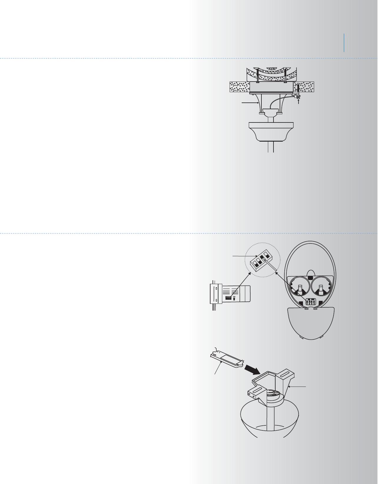
6
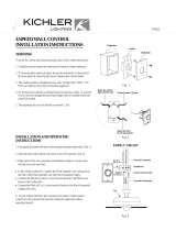
7. ELECTRICAL CONNECTIONS
Fig. 12
Fig. 13
Code Switch
Receiver
Ceiling Mounting
Bracket
WARNING: To avoid possible electrical
shock, be sure you have turned off the power
at the main circuit panel.
Follow the steps below to connect the fan to
your household wiring. Use the wire
connecting nuts suppled with your fan.
Secure the connectors with electrical tape.
Make sure there are no loose wire strands or
connections.
NOTE: The CoolTouch™ Control System is
equipped with 16 possible frequency
combinations to prevent interference from or
with other remote control units. The frequency
switches on your receiver and transmitter
have been preset at the factory. Please
recheck to make sure the switches on
transmitter and receiver are set to the same
position, any combination of settings will
operate the fan as long as the transmitter and
receiver are set to the same position. (Fig. 12)
Step 1. Insert the receiver in the ceiling
mounting bracket with the flat side of the
receiver facing the ceiling. (Fig. 13) For best
performance, make sure the Black Antenna,
on the end of the receiver, remains extended
and not tangled with any of the electrical
wires.
Fig. 11
6. INSTALLATION OF SAFETY SUPPORT
(required for Canadian installation ONLY)
A safety support cable is provided to help
prevent the ceiling fan from falling.
Step 1. Attach the provided wood screw and
washers to the ceiling joist next to the
mounting bracket but do not tighten. (Fig. 11)
Step 2. Adjust the length of the safety cable
to reach the screw and washers by pulling the
extra cable through the cable clamp until the
overall length is correct, put the end of the
cable back through the cable clamp, forming
a loop at the end of the cable. Tighten the
cable clamp securely. Now, put the loop in the
end of the safety cable over the wood screw
and under the washer. Tighten the wood
screw securely.
NOTE: Although the safety support cable is
required for Canadian installations only. It's a
good idea to make the attachment with any
installation.
Ceiling
mounting
bracket
Attach
safety cable
to ceiling joist
with screw and
washer
Monarch II
TM
Patio
7
Fig. 14
Step 2. Motor to Receiver Electrical
Connections: (Fig. 14)
Connect the black wire from the fan to the
black wire marked "TO MOTOR L" on the
receiver.
Connect the white wire from the fan to the
white wire marked "TO MOTOR N" on the
receiver.
Connect the blue wire from the fan to the blue
wire marked "FOR LIGHT" on the receiver.
NOTE: If the receiver included with your
ceiling fan has an "orange wire", Insure that it
has a wire nut attached to the end of the wire.
No exposed wire should show.
The Orange wire is used for decorative up
lighting on some models
Secure each set of wire connections with the
plastic wire nuts provided in the parts bag.
Step 3. (Fig. 14) Receiver to House Supply
Wires Electrical Connections:
Connect the black (hot) wire from the ceiling
to the black wire marked "AC in L" from the
receiver.
Connect the white(neutral) wire from the
ceiling to the white wire marked "AC in N"
from the Receiver.
Secure the wire connections with the plastic
wire nuts provided.
Step 4. (Fig. 14) If your outlet box has a
ground wire (green or bare copper) connect it
to the fan ground wires; otherwise connect the
hanging bracket ground wire to the mounting
bracket. Secure the wire connection with a
plastic nut provided. After connecting the
wires, spread them apart so that the green
and white wires are on one side of the outlet
box and black and blue wires are on the other
side. Carefully tuck the wire connections up
into the outlet box.
Note: Fan must be installed at a maximum
distance of 30 feet from the CoolTouch™
Remote Transmitter for optimal signal
transmission between the transmitter and the
fan's receiving unit.
White (neutral)
White (neutral)
Green or bare
copper (ground)
White ("AC IN N")
White ("to motor N")
Ground
(green)
(Connect to
ground wire on
hanger bracket
if no house
ground wire
exists.)
Outlet box
Black (hot)
Black ("AC IN L")
Black ("to motor L")
Receiver
Blue (for light)
Blue (for light)
Black (motor)

8
Step 1. Tuck all the connections neatly into
the ceiling outlet box.
Step 2. Slide the canopy up to the mounting
bracket and place one of the key hole slots
over the mounting screw on the mounting
bracket. Rotate the canopy until the screw
head locks in place at the narrow section of
the key hole. See figure 15.
Step 3. Align the remaining circular hole on
the canopy with the remaining hole on the
Ceiling Mounting Bracket. Insert and tighten
the mounting screw you removed earlier and
the mounting screw from Step 2 above. Now,
attach the canopy cover to the mounting
screw heads by inserting the screw heads into
the bottom side of the canopy cover and
rotating the cover clockwise.
NOTE: Adjust the canopy screws as
necessary until the canopy and canopy cover
are snug. (Fig. 15)
8. FINISHING THE INSTALLATION
Fig. 15
Outlet box
Ceiling mounting
brackrt
Canopy
Screw
Canopy cover
Screws
Monarch II
TM
Patio

Fig. 16
Fig. 17
9. ATTACHING THE FAN BLADES
9
10. INSTALLING THE SWITCH HOUSE
MOUNTING PLATE
CAUTION: Remove the five rubber shipping
blocks attached to the face of the motor.
These blocks keep the motor from shifting
during shipping and MUST be removed during
installation.
Step 1. Attach a blade to a blade bracket
using the screws and rubber washers
provided. (Fig. 16)
Make sure the blade is straight when set on
the blade bracket. Tighten each mounting
screw until the rubber washer is slightly
compressed. Repeat this procedure for each
blade.
Step 2. Attach each blade assembly to the
motor using the "Pre-Installed" mounting
screws in the blade bracket. (Fig 16)
Step 1. Loosen the two screws on the
mounting ring attached to the motor shaft and
"remove" and save the third screw. (Fig. 17)
Step 2. Place the key hole slots on the switch
house mounting plate over the two screws
previously loosened on the mounting ring.
Turn the switch house mounting plate until is
locks in place at the narrow section of the key
hole slots.
Tighten both key hole screws and replace the
third screw previously removed and tighten
securely.
Screws
Blades
Blade brackets
Screws
Rubber
washers
Switch house
mounting plate
Mounting ring
Screws
10
11. INSTALLING THE SWITCH HOUSING
Attach the switch housing to the mounting
plate with the screws provided. Make sure
each screw is tight. (Fig. 18)
Fig. 18
Fig. 19
Switch
housing
Screws
Switch house
mounting plate
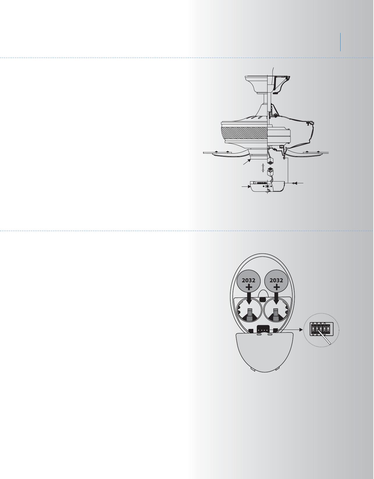
Remove the battery compartment cover on
the back of the CoolTouch™ Transmitter and
insert both batteries provided. Make sure the
+ sign is facing up.
Take care during this procedure NOT TO
move the frequency dip switches inside this
compartment. The settings MUST remain the
same as the settings on the receiver for
proper communication with the control
system.
It's a good idea to remove these batteries if
your fan is not used for extend periods of
time, (months).
NOTE: Make sure Dip Switch #5 is set to the
X position. This disables the dimming
function. You light fixture utilizes CFL lamps
that can NOT be dimmed.
12. INSTALLING THE BATTERIES
ON
1 2 3 4
D
X
ON
Code Switch
Monarch II
TM
Patio

Fig. 20
Fig. 21
13. OPERATING INSTRUCTIONS
Restore power to ceiling fan and test for
proper operation.
A. , , and buttons:
These three buttons are used to set the
fan speed as follows:
= High speed
= Medium speed
= High speed
B. button:
This button turns the fan off.
C. The " " button:
This button turns the light fixture On or
Off. Press and release once for either Off
or On.
It is designed for use with "Fluorescent Lamps".
This control is designed for use with "Fluorescent
Lamps". It is NOT designed to control dimming of
the light fixture.
At this time, using any control system that will dim
fluorescent lamps is not recommended. It could
damage the fixture and/or the lamps.
This control system is NOT designed to "Reverse"
the rotation of the blades. to set the fan blades in
reverse, locate the reverse slide switch located on
the side of the Switch Housing. See inset image
at left.
11
Slide switch
12
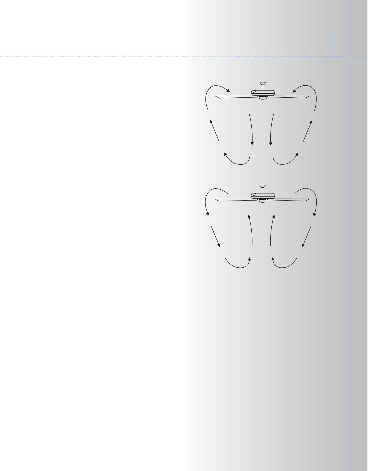
14. OPERATING INSTRUCTIONS
Fig. 22
Fig. 23
The Black Slide Switch on the side of the
switch housing controls the direction of the
blades "Forward and Reverse".
Warm weather - Forward (counter clockwise)
A downward airflow creates a cooling effect
as shown in Fig. 22. This allows you to set
your air conditioner on a warmer setting
without affecting your comfort.
Cool weather - Reverse (clockwise) An
upward airflow moves warm air off the ceiling
area as shown in Fig. 23. This allows you to
set your heating unit on a cooler setting
without affecting your comfort.
NOTE: To change the direction of rotation for
the fan blades, locate the reverse switch
located on the side of the switch housing.
Monarch II
TM
Patio
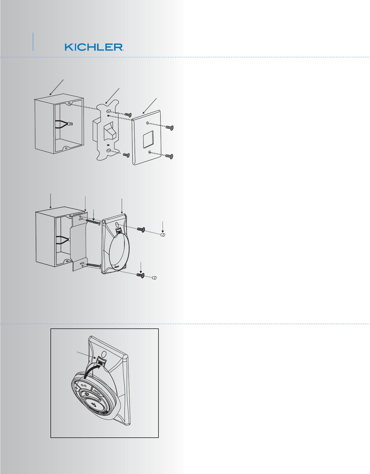
Fig. 24
Fig. 25
15. INSTALLING THE COOLTOUCH
™
CONTROL SYSTEM WALL PLATE
16. INSTALLING THE TRANSMITTER
1. Insert the transmitter into the wall plate by
inserting the bottom of the transmitter first
and then press the top of the transmitter into
the pocket. The transmitter will fully function
from this location or you can remove the
transmitter and use as a "Hand Held" device.
(Fig. 26)
2. To remove the transmitter from the wall
plate, push the release button and the
transmitter will fall into your hand.
Release
button
Fig. 26
Wall plate
Switch
Outlet box
Select a location to install your CoolTouch™
Control System Transmitter. You can replace
an existing wall switch or, install the
transmitter on ANY flat surface.
Option 1: Install the control system using an
existing wall switch outlet box.
Make sure the electrical power is TURNED
OFF at the main panel before continuing.
Step 1. Remove the existing wall plate and the
old switch from the wall outlet box. Wire nut
the BLACK leads (hot) together and push back
inside the outlet box. (Fig. 24)
Step 2. Install the metal plate and CoolTouch
™
wall plate to the existing wall outlet box with
4
screws provided. Then place the two plastic
plugs into the wall plate. (Fig. 25)
Option 2: Install the control system on ANY
flat surface.
Select the desired location and use the
CootTouch™ wall plate to mark the location
for the mounting holes. Use the dry wall
anchors and screws provided and finish the
installation.
Screws
Screws
Plastic plugs
CoolTouch
™
wall plate
Outlet box
Metal plate
13
Problem
Fan will not start.
Fan sounds noisy.
Fan wobble.
Remote control
malfunction.
Solution
1. Check circuit fuses or breakers.
2. Check all electrical connections to insure proper contact. CAUTION: Make sure the
main power is OFF when checking any electrical connection.
3. Make sure the transmitter batteries are installed properly. Positive (+) side facing
out.
4. Insure the batteries have a good charge.
1. Make sure all motor housing screws are snug.
2. Make sure the screws that attach the fan blade brackets to the motor are tight.
3. Make sure wire nut connections are not rubbing against each other or the interior
wall of the switch housing. CAUTION: Make sure main power is off.
4. Allow a 24-hour "breaking-in" period. Most noise associated with a new fan
disappear during this time.
5. If using an optional light kit, make sure the screws securing the glassware are tight.
Make sure the light bulbs are not touching any other component.
6. Do not connect this fan to wall mounted variable speed control(s). they are not
compatible with ceiling fan motors or remote controls.
7. Make sure the upper canopy is a short distance from the ceiling. It should not touch
the ceiling.
1. Check that all blade and blade arm screws are secure.
2. Most fan wobbling problems are caused when blade levels are unequal. Check this
level by selecting a point on the ceiling above the tip of one of the blades. Measure
this distance. Rotate the fan until the next blade is positioned for measurement.
Repeat for each blade. The distance deviation should be equal within 1/8".
3. Use the enclosed Blade Balancing Kit if the blade wobble is still noticeable.
4. If the blade wobble is still noticeable, interchanging two adjacent (side by side)
blades can redistribute the weight and possibly result in smoother operation.
WARNING: TO REDUCE THE RISK OF PERSONAL INJURY AND TO INUSRE THE
PROPER OPERATION OF YOUR CEILING FAN. NEVER ATTACH THE BLADE
ASSEMBLIES UNTIL THE CEILING FAN HAS BEEN MOUNTING ON THE CEILING. DO
NOT BEND THE BLADE ARMS WHILE INSTALLING, BALANCING OR CLEANING THE
FAN. DO NOT INSERT FOREIGN OBJECTS BETWEEN ROTATING FAN BLADES.
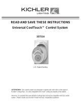
1. Ceiling Fans with remote control systems CAN NOT be operated in conjunction
with any other control system EXCEPT a basic On/Off wall switch, if desired.
2. Make sure the frequency dip switches in the transmitter and receiver have identical
settings.
3. Make sure the Black Antenna on the receiver is NOT tangled with any other
electrical wires and is extended around the inside of the ceiling canopy.
17. TROUBLESHOOTING
14
18. SPECIFICATIONS
These are approximate measurements. They do not include data for any lamps or fixtures
attached to the ceiling fan.
2.34'
11.78
kgs
12.78
kgs
0.60
0.46
0.33
70.70
29.00
12.60
178
109
60
6201.00
3848.00
2322.00
88
133
184
RPM
CFM CFM/W
N.W. G.W. C.F.
120
120
120
Fan Size
52"
Speed Volts
Amps
Watts
Low
Medium
High
Monarch II
TM
Patio
/