Eurotherm T940 Owner's manual
- Category
- Networking
- Type
- Owner's manual
This manual is also suitable for

HA028225
February 2012 (issue 8)
T940X Process Supervisor
Handbook

© 2012
All rights are strictly reserved. No part of this document may be reproduced, modified, or transmitted in any
form by any means, nor may it be stored in a retrieval system other than for the purpose to act as an aid in
operating the equipment to which the document relates, without prior written permission of the
manufacturer.
The manufacturer pursues a policy of continuous development and product improvement. The
specifications in this document may therefore be changed without notice. The information in this document
is given in good faith, but is intended for guidance only. The manufacturer will not accept responsibility for
any losses arising from errors in this document.

© 2011 Eurotherm Limited
All rights are strictly reserved. No part of this document may be reproduced, modified, or transmitted in any
form by any means, nor may it be stored in a retrieval system other than for the purpose to act as an aid in
operating the equipment to which the document relates, without the prior written permission of Eurotherm
limited.
Eurotherm Limited pursues a policy of continuous development and product improvement. The specifications
in this document may therefore be changed without notice. The information in this document is given in good
faith, but is intended for guidance only. Eurotherm Limited will accept no responsibility for any losses arising
from errors in this document.
E
UR
O
T
H
E
R
M
®
®
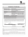
Declaration of Conformity
Manufacturer’s name: Eurotherm Limited
Manufacturer’s address: Faraday Close, Worthing, West Sussex,
BN13 3PL, United Kingdom
Product type: Process Supervisor
Models: T940X Processor module (Status level A1 or higher)
T320 Connection Module (Status level T12 or higher)
T310 Backplane (Status level T11 or higher)
Safety specication: BS EN61010-1: 2001-02
EMC emissions specication: BS EN61326 2002-02
EMC immunity specication: BS EN61326 2002-02
Eurotherm Limited hereby declares that the above products conform to the safety and EMC
specications listed. Eurotherm Limited further declares that the above products comply
with the EMC Directive 89 / 336 / EEC amended by 93 / 68 / EEC, and also with the Low
Voltage Directive 73 / 23 / EEC.
Signed: Dated:
Signed for and on behalf of Eurotherm Limited
William Davis
(General Manager)
IA249986U610 Issue 2 Aug 04

E
UR
O
T
H
E
R
M
®
®

PROCESSS SUPERVISOR HANDBOOK
HA028225
Issue 8 Feb 12
Contents
Page i
PROCESS SUPERVISOR HANDBOOK
LIST OF CHAPTERS
Section Title
Contents Contents
Chapter 1 Introduction
Chapter 2 Installation
Chapter 3 User interface
Chapter 4 Start-up
Chapter 5 Configuration
Chapter 6 Error conditions and diagnostics
Chapter 7 Task Scheduling and Tuning
Chapter 8 Service
Chapter 9 Specification and order codes
Annex A Terminal configurator
Index Index
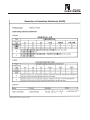
EFFECTIVITY
This manual refers to software version V5.2 for Process Supervisor units of the status levels listed below.
Please see earlier issues of this manual for instruments with earlier status levels. The status level appears as a
two or three character group, enclosed in parentheses ((T13) for example), at the end of the serial number.
T940X Processor unit (G6 or higher)
T320 Connect module (T11 or higher)
T310 Backplane (T11 or higher)
See The Modbus/Profibus manual (HA028104) for details of serial communications.

PROCESS SUPERVISOR HANDBOOK
Contents
Page ii
HA028225
Issue 8 Feb 12
LIST OF CONTENTS
Section Page
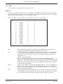
GLOSSARY OF TERMS ............................................. ix
Chapter 1 INTRODUCTION. . . . . . . . . . . . . . . . . . . . . . . . . . . . . . . . . . . . . . . . . 1-1
1.1 MANUAL CONTENTS . . . . . . . . . . . . . . . . . . . . . . . . . . . . . . . . . . . . . . . . . . . . . . . . . . . 1-1
1.2 OTHER INFORMATION SOURCES . . . . . . . . . . . . . . . . . . . . . . . . . . . . . . . . . . . . . . . . . 1-1
1.3 THE PROCESS SUPERVISOR UNITS . . . . . . . . . . . . . . . . . . . . . . . . . . . . . . . . . . . . . . . . 1-1
1.3.1 Typical applications ................................................ 1-2
1.3.2 Features . . . . . . . . . . . . . . . . . . . . . . . . . . . . . . . . . . . . . . . . . . . . . . . . . . . . . . . . . 1-2
LIN . . . . . . . . . . . . . . . . . . . . . . . . . . . . . . . . . . . . . . . . . . . . . . . . . . . . . . . . . . . . . . . 1-2
MODBUS . . . . . . . . . . . . . . . . . . . . . . . . . . . . . . . . . . . . . . . . . . . . . . . . . . . . . . . . . 1-2
PROFIBUS. . . . . . . . . . . . . . . . . . . . . . . . . . . . . . . . . . . . . . . . . . . . . . . . . . . . . . . . . 1-2
REDUNDANT PROCESSOR MODULES . . . . . . . . . . . . . . . . . . . . . . . . . . . . . . . . . . . 1-2
AUTOMATIC TAKE-OVER ............................................. 1-2
REDUNDANT POWER SUPPLY CONNECTION ............................. 1-2
LIVE PROCESSOR REPLACEMENT ...................................... 1-2
DIAGNOSTICS . . . . . . . . . . . . . . . . . . . . . . . . . . . . . . . . . . . . . . . . . . . . . . . . . . . . . 1-2
FRONT PANEL ANNUNCIATION. . . . . . . . . . . . . . . . . . . . . . . . . . . . . . . . . . . . . . . 1-2
CONTINUOUS HEALTH MONITORING .................................. 1-2
WATCHDOG ....................................................... 1-3
I/O . . . . . . . . . . . . . . . . . . . . . . . . . . . . . . . . . . . . . . . . . . . . . . . . . . . . . . . . . . . . . . 1-3
CONFIGURATION. .................................................. 1-3
BLOCK STRUCTURE. . . . . . . . . . . . . . . . . . . . . . . . . . . . . . . . . . . . . . . . . . . . . . . . . 1-3
ST USER ALGORITHMS . . . . . . . . . . . . . . . . . . . . . . . . . . . . . . . . . . . . . . . . . . . . . . 1-3
BLOCK SUPPORT .................................................... 1-3
ENCLOSURES ...................................................... 1-3
Chapter 2 INSTALLATION .......................................... 2-1
2.1 SAFETY AND EMC INFORMATION. . . . . . . . . . . . . . . . . . . . . . . . . . . . . . . . . . . . . . . . . 2-1
2.1.1 Installation requirements for EMC .................................... 2-1
2.1.2 Installation safety requirements ...................................... 2-2
PERSONNEL . . . . . . . . . . . . . . . . . . . . . . . . . . . . . . . . . . . . . . . . . . . . . . . . . . . . . . . . 2-2
HAZARDOUS VOLTAGES .............................................. 2-2
CONDUCTIVE POLLUTION ............................................ 2-2
VENTILATION ....................................................... 2-2
PRECAUTIONS AGAINST ELECTROSTATIC DISCHARGE ..................... 2-2
2.1.3 Keeping the product safe . . . . . . . . . . . . . . . . . . . . . . . . . . . . . . . . . . . . . . . . . . . 2-2
MISUSE OF EQUIPMENT .............................................. 2-2
SERVICE AND REPAIRS . . . . . . . . . . . . . . . . . . . . . . . . . . . . . . . . . . . . . . . . . . . . . . . 2-2
2.2 UNPACKING . . . . . . . . . . . . . . . . . . . . . . . . . . . . . . . . . . . . . . . . . . . . . . . . . . . . . . . . . 2-2
2.2.1 Handling precautions . . . . . . . . . . . . . . . . . . . . . . . . . . . . . . . . . . . . . . . . . . . . . . 2-3
2.2.2 Package contents .................................................. 2-3
PRODUCT LABELLING . . . . . . . . . . . . . . . . . . . . . . . . . . . . . . . . . . . . . . . . . . . . . . . 2-3
2.3 MECHANICAL LAYOUT AND INSTALLATION ................................ 2-3
2.3.1 Layout drawings ................................................... 2-4
2.3.2 Removal of modules ............................................... 2-5
2.3.3 Fitting of modules . . . . . . . . . . . . . . . . . . . . . . . . . . . . . . . . . . . . . . . . . . . . . . . . 2-5
2.4 BACKPLANE SWITCHES . . . . . . . . . . . . . . . . . . . . . . . . . . . . . . . . . . . . . . . . . . . . . . . . . 2-6
2.4.1 Location . . . . . . . . . . . . . . . . . . . . . . . . . . . . . . . . . . . . . . . . . . . . . . . . . . . . . . . . . 2-6

PROCESSS SUPERVISOR HANDBOOK
HA028225
Issue 8 Feb 12
Contents
Page iii
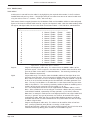
LIST OF CONTENTS (CONT.)
Section Page
2.4.2 Switch functions . . . . . . . . . . . . . . . . . . . . . . . . . . . . . . . . . . . . . . . . . . . . . . . . . . 2-6
SW1: LIN ADDRESS SETTING SWITCH . . . . . . . . . . . . . . . . . . . . . . . . . . . . . . . . . . . 2-6
Sw2: OPTIONS SWITCH . . . . . . . . . . . . . . . . . . . . . . . . . . . . . . . . . . . . . . . . . . . . . . 2-7
WDR (WATCHDOG RETRY) ............................................ 2-7
MDB (MODBUS ENABLE) . . . . . . . . . . . . . . . . . . . . . . . . . . . . . . . . . . . . . . . . . . . . . 2-7
SRD (REDUNDANCY DISABLE) ......................................... 2-7
2.5 CONNECTIONS AND WIRING ............................................ 2-8
2.5.1 Connect module . . . . . . . . . . . . . . . . . . . . . . . . . . . . . . . . . . . . . . . . . . . . . . . . . . 2-9
COMMUNICATIONS CONNECTORS ..................................... 2-10
ELIN CONNECTORS . . . . . . . . . . . . . . . . . . . . . . . . . . . . . . . . . . . . . . . . . . . . . . . . . 2-11
ALIN CONNECTORS ................................................. 2-12
ELIN HUBS . . . . . . . . . . . . . . . . . . . . . . . . . . . . . . . . . . . . . . . . . . . . . . . . . . . . . . . . . 2-13
ALIN HUBS (ACTIVE) ................................................. 2-13
ALIN HUBS (PASSIVE) . . . . . . . . . . . . . . . . . . . . . . . . . . . . . . . . . . . . . . . . . . . . . . . . 2-14
DAISY-CHAIN LAYOUT . . . . . . . . . . . . . . . . . . . . . . . . . . . . . . . . . . . . . . . . . . . . . . . 2-14
CABLING ........................................................... 2-14
DC SUPPLY WIRING .................................................. 2-15
RELAY WIRING ...................................................... 2-16
2.5.2 Processor module . . . . . . . . . . . . . . . . . . . . . . . . . . . . . . . . . . . . . . . . . . . . . . . . . 2-17
CONFIGURATION OF CONTROL STRATEGIES AND SEQUENCES . . . . . . . . . . . . . 2-19
TERMINAL CONFIGURATOR RESTRICTIONS . . . . . . . . . . . . . . . . . . . . . . . . . . . . . . 2-19
2.5.3 Safety earth connection ............................................ 2-19
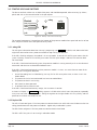
2.5.4 Transparent Modbus Access (TMA) . . . . . . . . . . . . . . . . . . . . . . . . . . . . . . . . . . 2-20
Chapter 3 USER INTERFACE ........................................ 3-1
3.1 INTRODUCTION . . . . . . . . . . . . . . . . . . . . . . . . . . . . . . . . . . . . . . . . . . . . . . . . . . . . . . . 3-1
3.2 POWER MONITORING LEDs . . . . . . . . . . . . . . . . . . . . . . . . . . . . . . . . . . . . . . . . . . . . . . 3-3
3.2.1 A and B .......................................................... 3-3
3.2.2 ext . . . . . . . . . . . . . . . . . . . . . . . . . . . . . . . . . . . . . . . . . . . . . . . . . . . . . . . . . . . . . 3-3
3.2.3 int .............................................................. 3-3
3.3 ALARM LEDS .......................................................... 3-4
3.4 COMMS LEDs ......................................................... 3-5
3.4.1 System A/B, i/oA, i/oB . . . . . . . . . . . . . . . . . . . . . . . . . . . . . . . . . . . . . . . . . . . . . 3-5
3.4.2 Exp1 tx/rx ........................................................ 3-5
3.4.3 Exp2 tx/rx . . . . . . . . . . . . . . . . . . . . . . . . . . . . . . . . . . . . . . . . . . . . . . . . . . . . . . . 3-5
3.5 CHANGEOVER LEDs AND SWITCHES ....................................... 3-6
3.5.1 Primary LED . . . . . . . . . . . . . . . . . . . . . . . . . . . . . . . . . . . . . . . . . . . . . . . . . . . . . . 3-6
3.5.2 Standby LED ...................................................... 3-6
3.5.3 Sync/changeover switch ............................................ 3-6
3.5.4 Desync switch . . . . . . . . . . . . . . . . . . . . . . . . . . . . . . . . . . . . . . . . . . . . . . . . . . . . 3-6
3.5.5 Processor module Synchronisation . . . . . . . . . . . . . . . . . . . . . . . . . . . . . . . . . . . 3-7
TIME TO SYNCHRONISE . . . . . . . . . . . . . . . . . . . . . . . . . . . . . . . . . . . . . . . . . . . . . . 3-7
3.6 STARTUP LEDS AND SWITCHES ........................................... 3-8
3.6.1 wdog LED ........................................................ 3-8
3.6.2 Duplex LED . . . . . . . . . . . . . . . . . . . . . . . . . . . . . . . . . . . . . . . . . . . . . . . . . . . . . . . 3-8
3.6.3 Restart switch . . . . . . . . . . . . . . . . . . . . . . . . . . . . . . . . . . . . . . . . . . . . . . . . . . . . 3-9
3.6.4 Halt switch ........................................................ 3-9

PROCESS SUPERVISOR HANDBOOK
Contents
Page iv
HA028225
Issue 8 Feb 12
LIST OF CONTENTS (CONT.)
Section Page
3.6.5 Start up mode ..................................................... 3-9
HOT ............................................................... 3-9
COLD .............................................................. 3-9
HOT/COLD ......................................................... 3-9
TEST . . . . . . . . . . . . . . . . . . . . . . . . . . . . . . . . . . . . . . . . . . . . . . . . . . . . . . . . . . . . . . 3-9
Chapter 4 START-UP ............................................. 4-1
4.1 REDUNDANCY MODES .................................................. 4-1
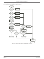
4.2 START-UP MODES ..................................................... 4-1
4.2.1 Hot start ......................................................... 4-3
4.2.2 Hot/cold start . . . . . . . . . . . . . . . . . . . . . . . . . . . . . . . . . . . . . . . . . . . . . . . . . 4-3
4.2.3 Cold start ........................................................ 4-3
4.2.4 Test start . . . . . . . . . . . . . . . . . . . . . . . . . . . . . . . . . . . . . . . . . . . . . . . . . . . . . 4-3
4.2.5 Reset Data Set ................................................. 4-4
4.3 STARTING A SINGLE (NON REDUNDANT) PROCESSOR ........................ 4-5
4.3.1 Start-up sequence ................................................. 4-5
OFF STATE . . . . . . . . . . . . . . . . . . . . . . . . . . . . . . . . . . . . . . . . . . . . . . . . . . . . . . . . . 4-5
STARTING STATE . . . . . . . . . . . . . . . . . . . . . . . . . . . . . . . . . . . . . . . . . . . . . . . . . . . . 4-5
PRIMARY UNSYNCH STATE . . . . . . . . . . . . . . . . . . . . . . . . . . . . . . . . . . . . . . . . . . 4-6
4.3.2 Watchdog indications .............................................. 4-6
4.3.3 Watchdog relay ................................................... 4-6
4.4 STARTING UP A PAIR OF PROCESSORS ..................................... 4-7
4.4.1 Redundant mode .................................................. 4-7
PRIMARY/SECONDARY CRITERIA . . . . . . . . . . . . . . . . . . . . . . . . . . . . . . . . . . . . . . 4-7
AUTOSYNCHRONISATION ............................................ 4-8
SYNCHRONISATION . . . . . . . . . . . . . . . . . . . . . . . . . . . . . . . . . . . . . . . . . . . . . . . . . 4-8
TIME TO SYNCHRONISE . . . . . . . . . . . . . . . . . . . . . . . . . . . . . . . . . . . . . . . . . . . . . . 4-8
4.4.2 Non-redundant mode .............................................. 4-8
4.5 LED FAULT INDICATIONS ................................................ 4-9
POWER A/B LEDs .................................................... 4-9
WATCHDOG LED . . . . . . . . . . . . . . . . . . . . . . . . . . . . . . . . . . . . . . . . . . . . . . . . . . . . 4-9
PRIMARY LED . . . . . . . . . . . . . . . . . . . . . . . . . . . . . . . . . . . . . . . . . . . . . . . . . . . . . . 4-9
COMMS LEDs ....................................................... 4-9
SYSTEM AND I/O LEDS. . . . . . . . . . . . . . . . . . . . . . . . . . . . . . . . . . . . . . . . . . . . . . 4-9
EXP1, EXP2 LEDS. ................................................... 4-10
DUPLEX LED ........................................................ 4-10
Chapter 5 CONFIGURATION ........................................ 5-1
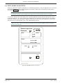
5.1 THE TERMINAL CONFIGURATOR .......................................... 5-1
5.1.1 Configuration Access ............................................... 5-1
5.1.2 Connecting to a PC . . . . . . . . . . . . . . . . . . . . . . . . . . . . . . . . . . . . . . . . . . . . . . . . 5-1
5.1.3 Running the configurator . . . . . . . . . . . . . . . . . . . . . . . . . . . . . . . . . . . . . . . . . . . 5-1
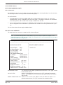
INITIAL MENU ACCESS . . . . . . . . . . . . . . . . . . . . . . . . . . . . . . . . . . . . . . . . . . . . . . . 5-2
THE INITIAL MENU .................................................. 5-4
QUITTING THE TERMINAL EMULATION PROGRAM . . . . . . . . . . . . . . . . . . . . . . . 5-4
5.1.4 Database configuration ............................................. 5-5
UTILITIES . . . . . . . . . . . . . . . . . . . . . . . . . . . . . . . . . . . . . . . . . . . . . . . . . . . . . . . . . . 5-5

PROCESSS SUPERVISOR HANDBOOK
HA028225
Issue 8 Feb 12
Contents
Page v
LIST OF CONTENTS (CONT.)
Section Page
5.2 LINTOOLS ON-LINE RECONFIGURATION . . . . . . . . . . . . . . . . . . . . . . . . . . . . . . . . . . 5-8
5.2.1 On-line Reconfiguration ............................................ 5-8
5.2.2 Preparing to run LINtools ........................................... 5-9
CONNECTING TO A COMPUTER ........................................ 5-9
CREATING A PROJECT FOLDER ......................................... 5-9
5.2.3 Running LINtools .................................................. 5-10
UPLOADING AN INSTRUMENT CONTROL STRATEGY ....................... 5-10
DOWNLOADING AN INSTRUMENT CONTROL STRATEGY ................... 5-10
RECONFIGURING INSTRUMENT CONTROL STRATEGY ...................... 5-10
5.3 MODBUS TOOLS ....................................................... 5-11
5.3.1 Preparing to run Modbus Tools . . . . . . . . . . . . . . . . . . . . . . . . . . . . . . . . . . . . . . 5-11
5.3.2 Running Modbus Tools ............................................. 5-11
Chapter 6 ERROR CONDITIONS & DIAGNOSTICS ........................ 6-1
6.1 ERROR INDICATION TYPES .............................................. 6-1
6.2 PROCESSOR MODULE FRONT PANEL ERROR DISPLAYS . . . . . . . . . . . . . . . . . . . . . . . 6-2
6.2.2 Processor failure modes ............................................ 6-4
6.2.3 Power failure ..................................................... 6-5
PRIMARY PROCESSOR MODULE . . . . . . . . . . . . . . . . . . . . . . . . . . . . . . . . . . . . . . . 6-5
SECONDARY PROCESSOR MODULE ..................................... 6-5
6.2.4 Watchdog failure .................................................. 6-5
6.2.5 ICM (Inter-CPU Messaging for redundancy) failure ...................... 6-5
ACTION IN THE EVENT OF ICM FAILURE . . . . . . . . . . . . . . . . . . . . . . . . . . . . . . . . 6-6
6.2.6 LIN failure . . . . . . . . . . . . . . . . . . . . . . . . . . . . . . . . . . . . . . . . . . . . . . . . . . . . . . . 6-6
EFFECT OF LIN FAILURE ON REDUNDANCY MODE CONTROL . . . . . . . . . . . . . . . 6-6
6.2.7 Database stop . . . . . . . . . . . . . . . . . . . . . . . . . . . . . . . . . . . . . . . . . . . . . . . . . . . . 6-7
6.2.8 I/O Comms failure ................................................. 6-7
6.3 POWER-UP FAILURE .................................................... 6-7
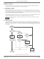
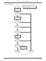
6.3.1 Processor unit power-up routine ..................................... 6-7
6.4 POSTs (POWER ON SELF TESTS) . . . . . . . . . . . . . . . . . . . . . . . . . . . . . . . . . . . . . . . . . . 6-10
ERROR TYPES ....................................................... 6-12
6.5 DIAGNOSTIC BLOCKS. . . . . . . . . . . . . . . . . . . . . . . . . . . . . . . . . . . . . . . . . . . . . . . . . . . 6-12
6.6 ERROR NUMBERS ...................................................... 6-13
6.6.1 Error number structure ............................................. 6-13
RUNNING PACKAGES . . . . . . . . . . . . . . . . . . . . . . . . . . . . . . . . . . . . . . . . . . . . . . . . 6-13
6.6.2 Error messages. . . . . . . . . . . . . . . . . . . . . . . . . . . . . . . . . . . . . . . . . . . . . . . . . . . . 6-13
Chapter 7 TASK ORGANISATION & TUNING ............................ 7-1
7.1 TASK SCHEDULING ..................................................... 7-1
7.1.1 Tasks . . . . . . . . . . . . . . . . . . . . . . . . . . . . . . . . . . . . . . . . . . . . . . . . . . . . . . . . . . . . 7-1
7.1.2 Priorities ......................................................... 7-1
7.1.3 Task Functions . . . . . . . . . . . . . . . . . . . . . . . . . . . . . . . . . . . . . . . . . . . . . . . . . . . . 7-1
NETWORK TASK . . . . . . . . . . . . . . . . . . . . . . . . . . . . . . . . . . . . . . . . . . . . . . . . . . . . 7-1
NFS TASK . . . . . . . . . . . . . . . . . . . . . . . . . . . . . . . . . . . . . . . . . . . . . . . . . . . . . . . . . . 7-1
USER TASKS 1 TO 4 .................................................. 7-1
CACHE SYNC SERVER . . . . . . . . . . . . . . . . . . . . . . . . . . . . . . . . . . . . . . . . . . . . . . . . 7-1
CACHE CONN SERVER ................................................ 7-1
LLC TASK . . . . . . . . . . . . . . . . . . . . . . . . . . . . . . . . . . . . . . . . . . . . . . . . . . . . . . . . . . 7-2

PROCESS SUPERVISOR HANDBOOK
Contents
Page vi
HA028225
Issue 8 Feb 12
LIST OF CONTENTS (CONT.)
Section Page
LOAD TASK ......................................................... 7-2
BGND TASK (Scan) . . . . . . . . . . . . . . . . . . . . . . . . . . . . . . . . . . . . . . . . . . . . . . . . . . 7-2
IDLE TASK .......................................................... 7-2
7.2 USER TASKS ........................................................... 7-3
7.2.1 Terminology ...................................................... 7-3
USER TASK ......................................................... 7-3
SERVER ............................................................ 7-3
7.2.2 User task servers .................................................. 7-3
SERVER INTERACTIONS ............................................... 7-3
USER TASK SERVER OPERATION ........................................ 7-4
7.3 USER TASK TUNING . . . . . . . . . . . . . . . . . . . . . . . . . . . . . . . . . . . . . . . . . . . . . . . . . . . . 7-5
7.3.1 Repeat times & execution times ...................................... 7-5
7.3.2 Automatic dynamic tuning .......................................... 7-5
7.3.3 Manual tuning . . . . . . . . . . . . . . . . . . . . . . . . . . . . . . . . . . . . . . . . . . . . . . . . . . . . 7-5
7.4 DATA COHERENCE ..................................................... 7-6
7.4.1 Data flow between tasks ............................................ 7-6
CONNECTIONS INTO TASKS (FROM OTHER TASKS IN THE SAME INSTRUMENT (NODE))
7-6
CONNECTIONS INTO THIS TASK (FROM OTHER TASKS IN ANOTHER INSTRUMENT)
7-6
CONNECTIONS OUT OF THIS TASK TO ANOTHER NODE . . . . . . . . . . . . . . . . . . . 7-7
Chapter 8 SERVICE ............................................... 8-1
8.1 PREVENTIVE MAINTENANCE SCHEDULE . . . . . . . . . . . . . . . . . . . . . . . . . . . . . . . . . . . 8-1
8.2 REPLACEMENT PROCEDURES ............................................ 8-2
8.2.1 Chassis fan filter replacement . . . . . . . . . . . . . . . . . . . . . . . . . . . . . . . . . . . . . . . 8-2
8.2.2 Chassis Fan replacement ............................................ 8-3
8.2.3 Capacitor board / capacitor board fan replacement ..................... 8-4
8.2.4 Battery fitting . . . . . . . . . . . . . . . . . . . . . . . . . . . . . . . . . . . . . . . . . . . . . . . . . . . . 8-5
PROCEDURE ........................................................ 8-5
8.2.5 Flash card Replacement . . . . . . . . . . . . . . . . . . . . . . . . . . . . . . . . . . . . . . . . . . . . 8-5
8.2.6 Firmware upgrade ................................................. 8-5
8.3 PHYSICAL ARRANGEMENT INSIDE PROCESSOR MODULE ..................... 8-6
8.4 THE MONITOR . . . . . . . . . . . . . . . . . . . . . . . . . . . . . . . . . . . . . . . . . . . . . . . . . . . . . . . . 8-7
8.4.1 Top level (main) menu access . . . . . . . . . . . . . . . . . . . . . . . . . . . . . . . . . . . . . . . . 8-7
8.4.2 Quit . . . . . . . . . . . . . . . . . . . . . . . . . . . . . . . . . . . . . . . . . . . . . . . . . . . . . . . . . . . . 8-7
8.4.3 Help . . . . . . . . . . . . . . . . . . . . . . . . . . . . . . . . . . . . . . . . . . . . . . . . . . . . . . . . . . . . 8-7
8.4.4 Display saved system features ........................................ 8-8
8.4.5 Diagnostics menu ................................................. 8-8
AUTOMATIC TEST SEQUENCE. . . . . . . . . . . . . . . . . . . . . . . . . . . . . . . . . . . . . . . . . . 8-9
PSE COMM TEST MENU . . . . . . . . . . . . . . . . . . . . . . . . . . . . . . . . . . . . . . . . . . . . . . 8-9
PSE COMM TEST (Cont.) .............................................. 8-10
NET MENU ......................................................... 8-10
PROFIBUS TEST . . . . . . . . . . . . . . . . . . . . . . . . . . . . . . . . . . . . . . . . . . . . . . . . . . . . . 8-10
PROFIBUS TEST (Cont.) ............................................... 8-11
MASTER DATA SCREEN ............................................... 8-11
PROFIBUS TEST (Cont.) ............................................... 8-12
SLAVE DATA SCREEN ................................................. 8-12

PROCESSS SUPERVISOR HANDBOOK
HA028225
Issue 8 Feb 12
Contents
Page vii
LIST OF CONTENTS (CONT.)
Section Page
8.4.6 Manual set-up . . . . . . . . . . . . . . . . . . . . . . . . . . . . . . . . . . . . . . . . . . . . . . . . . . . . 8-14
8.4.7 Automatic set-up .................................................. 8-14
WATCHDOG RELAY TEST .............................................. 8-14
RL1 RELAY TEST ..................................................... 8-15
RL2 RELAY TEST ..................................................... 8-15
COMMUNICATIONS HARDWARE CHECK ................................. 8-15
8.4.8 The ‘S’ Monitor ................................................... 8-16
S MONITOR ACCESS . . . . . . . . . . . . . . . . . . . . . . . . . . . . . . . . . . . . . . . . . . . . . . . . . 8-16
QUIT .............................................................. 8-16
HELP . . . . . . . . . . . . . . . . . . . . . . . . . . . . . . . . . . . . . . . . . . . . . . . . . . . . . . . . . . . . . . 8-16
DISPLAY BASIC MACHINE STATUS ...................................... 8-17
DISPLAY EXTENDED MACHINE STATUS .................................. 8-17
DIAGNOSTICS MENU ................................................. 8-18
MEMORY STATUS. . . . . . . . . . . . . . . . . . . . . . . . . . . . . . . . . . . . . . . . . . . . . . . . . . . . 8-20
SHOW BOOT INFO ................................................... 8-20
DATE /TIME SET ..................................................... 8-20
Chapter 9 SPECIFICATION AND ORDER CODES .......................... 9-1
INSTALLATION CATEGORY AND POLLUTION DEGREE ............................ 9-1
Installation category II. . . . . . . . . . . . . . . . . . . . . . . . . . . . . . . . . . . . . . . . . . . . . . . . . . . 9-1
Pollution degree 2 ...................................................... 9-1
9.1 SPECIFICATION . . . . . . . . . . . . . . . . . . . . . . . . . . . . . . . . . . . . . . . . . . . . . . . . . . . . . . . . 9-2
9.1.1 General specification ............................................... 9-2
9.1.2 Backplane specification ............................................. 9-2
9.1.3 Connect module specification . . . . . . . . . . . . . . . . . . . . . . . . . . . . . . . . . . . . . . . 9-3
9.1.4 Processor Module specification . . . . . . . . . . . . . . . . . . . . . . . . . . . . . . . . . . . . . . 9-4
9.1.5 Software specification .............................................. 9-5
9.2 ORDER CODES ........................................................ 9-6
9.2.1 Instrument order code . . . . . . . . . . . . . . . . . . . . . . . . . . . . . . . . . . . . . . . . . . . . . 9-6
9.2.2 Spares and accessories .............................................. 9-7
9.3 COSHH ............................................................... 9-8
9.3.1 Lithium thionyl chloride batteries . . . . . . . . . . . . . . . . . . . . . . . . . . . . . . . . . . . . 9-8
ANNEX A CONFIGURATION ........................................ A-1
A.1 TOOLS: THE CONFIGURATOR AND LINTOOLS . . . . . . . . . . . . . . . . . . . . . . . . . . . . . . A-1
A.2 CONFIGURABLE ITEMS . . . . . . . . . . . . . . . . . . . . . . . . . . . . . . . . . . . . . . . . . . . . . . . . . A-1
A.2.1 Configuration Access . . . . . . . . . . . . . . . . . . . . . . . . . . . . . . . . . . . . . . . . . . . . . . A-2
A.3 PREPARING TO RUN THE CONFIGURATOR . . . . . . . . . . . . . . . . . . . . . . . . . . . . . . . . . A-2
A.3.1 Connecting to a PC ................................................ A-2
A.3.2 Setting the control efficiency ....................................... A-2
NON-REDUNDANT (SIMPLEX)SYSTEM .................................. A-2
REDUNDANT (DUPLEX)SYSTEM ....................................... A-2
A.4 RUNNING THE CONFIGURATOR . . . . . . . . . . . . . . . . . . . . . . . . . . . . . . . . . . . . . . . . . A-3
A.4.1 Initial menu access . . . . . . . . . . . . . . . . . . . . . . . . . . . . . . . . . . . . . . . . . . . . . . . . A-3
IP SUBNETS . . . . . . . . . . . . . . . . . . . . . . . . . . . . . . . . . . . . . . . . . . . . . . . . . . . . . . . . A-4
A.4.2 The Initial menu .................................................. A-5
A.4.3 Quitting the terminal emulation program . . . . . . . . . . . . . . . . . . . . . . . . . . . . . A-5

PROCESS SUPERVISOR HANDBOOK
Contents
Page viii
HA028225
Issue 8 Feb 12
LIST OF CONTENTS (CONT.)
Section Page
A5 DATABASE CONFIGURATION ............................................. A-5
A.5.1 MAKE ........................................................... A-6
BLOCK OVERVIEW ................................................... A-7
CONNECTION TYPES IN A PROCESSOR MODULE DATABASE ................ A-11
A.5.2 COPY command . . . . . . . . . . . . . . . . . . . . . . . . . . . . . . . . . . . . . . . . . . . . . . . . . . A-12
A.5.3 DELETE command ................................................. A-13
A.5.4 INSPECT command . . . . . . . . . . . . . . . . . . . . . . . . . . . . . . . . . . . . . . . . . . . . . . . . A-13
A.5.5 NETWORK ........................................................ A-13
A.5.6 UTILITIES . . . . . . . . . . . . . . . . . . . . . . . . . . . . . . . . . . . . . . . . . . . . . . . . . . . . . . . . A-14
START, STOP COMMANDS ............................................ A-14
SAVE COMMAND ................................................... A-14
LOAD COMMAND ................................................... A-15
FILE COMMAND ..................................................... A-15
TRY/UNTRY CHANGES COMMAND . . . . . . . . . . . . . . . . . . . . . . . . . . . . . . . . . . . . . A-15
APPLY/UNDO COMMAND. . . . . . . . . . . . . . . . . . . . . . . . . . . . . . . . . . . . . . . . . . . . . A-15
APPLY/UNDO COMMAND (Cont.) ...................................... A-16
ELIN SETUP PAGE COMMAND ......................................... A-16
ELIN SETUP PAGE COMMAND (Cont.) ................................... A-17
LOCAL IP SETUP ..................................................... A-17
ELIN PARAMETERS ................................................... A-17
A.5.7 ALARMS ......................................................... A-17
A.6 MODBUS CONFIGURATION ............................................. A-18
A.6.1 MODE ........................................................... A-18
A.6.2 SETUP ........................................................... A-18
A.6.3 Tables .......................................................... A-19
TABLES LIST . . . . . . . . . . . . . . . . . . . . . . . . . . . . . . . . . . . . . . . . . . . . . . . . . . . . . . . . A-19
TABLE MENUS . . . . . . . . . . . . . . . . . . . . . . . . . . . . . . . . . . . . . . . . . . . . . . . . . . . . . . A-20
A.6.4 Utilities . . . . . . . . . . . . . . . . . . . . . . . . . . . . . . . . . . . . . . . . . . . . . . . . . . . . . . . . . A-22
INDEX . . . . . . . . . . . . . . . . . . . . . . . . . . . . . . . . . . . . . . . . . . . . . . . . . . . . . . . . i

PROCESSS SUPERVISOR HANDBOOK
HA028225
Issue 8 Feb 12
Contents
Page ix
GLOSSARY OF TERMS
Items in italics in the descriptions below also appear as glossary items in their own right
2500 I/O sub-system for use with Process Supervisor units
ALIN Local Instrument Network (LIN) protocol on ARCNET
ALIN bridge LIN to ALIN network link
Application A LIN database and associated SFCs
ARCNET A single non-branching, masterless network, running at 2.5MBaud allowing peer-to-peer
communications and file transfer up to 100 metres.
Baud Used to describe transmission speeds over communications links. (9600 baud = approxi-
mately 1000 ASCII characters per second)
Brown-out A brown-out is a transient power variation or partial power failure severe enough to
prevent continuation of the process until the process supervisor has been re-initialised.
Cold start A Cold start is where the instrument starts with the last-loaded database loaded using
either default parameters or parameters held in the cold start parameter file. See also
Hot Start
Cold Start time The Cold Start time is a pre-set duration, following power off, after which a Hot Start is
not possible, and a Cold Start must be initiated instead.
Configuration The process of specifying the components of an application.
Control strategy A control strategy is the overall programmed function of the LIN database within an
instrument, ready to act upon a real life process.
CIDR Classless Inter-domain Routing. A standard for IP addressing.
COSHH Control of Substances Hazardous to Health legislation
CSP Cold Start Primary - the left-hand processor module. Applies to redundant mode systems
only.
CSS Cold Start Secondary - the right-hand processor module. Applies to redundant mode sys-
tems only.
DRAM Dynamic Random Access Mamory
Duplex Twin synchronised processors capable of operating in redundant mode
EDB External database
EEPROM Electrically Erasable Programmable Read Only Memory
ELIN Local Instrument Network (LIN) protocol on Ethernet
EMC Electro-magnetic compliance
Eurotherm Project Studio
A suite of programs for building, testing and configuring programs and systems for proc-
ess control and I/O.
e-Suite A control/monitoring/configuration system for use with process supervisor units.
FB Function block.
FBD Function Block Diagram - a programming language.
Function block A unit of software that performs a named function. It can be linked to other function
blocks to build a LIN database and hence a control strategy for an instrument.
GSD file A GSD (Gerätestammdaten) file contains instrument parameter information, which a
Profibus master needs in order to communicate with the instrument.
Hot start After a power loss, the instrument attempts to re-start with the current database still
loaded and with all parameters and values for that application still at the values they
held when processing stopped. If the restart fails the processor enters an idle state.
Hot & Cold start: After a power loss, the instrument attempts to re-start with the current database still
loaded and with all parameters and values for that application still at the values they
held when processing stopped. If the restart fails the processor attempts a cold start.
ICM Inter-CPU Messaging for redundancy.
Idle A state in which the processor module is powered up, but with an empty database. This
state is entered as a result of ‘test’ being selected as start-up mode, or if a hot start or
cold start is not successful.
IP Internet Protocol.

PROCESS SUPERVISOR HANDBOOK
Contents
Page x
HA028225
Issue 8 Feb 12
iTools A Eurotherm utility for configuring networks of Eurotherm I/O controllers.GLOSSARY
(Cont.)
LIN Local Instrument Network, a Eurotherm proprietary system for networking process moni-
toring and control instruments.
LIN database The LIN database is a set of software function blocks that constitute the control strategy
of a LIN instrument.
LIN protocol The communications protocol employed to control instruments linked by a LIN.
LINtools A Eurotherm utility for configuring networks of LIN instruments.
Modbus® A proprietary communications protocol (Gould-Modicon Modbus RTU).
Non-redundant mode
One or more processors running but not synchronised.
PAL Programmable Logic Array.
Primary In a Redundant mode system, the primary is that processor which is in control. The other
processor is called the secondary processor.
Processor module The process supervisor consists of a backplane fitted with one or two Processor Modules
and a connection module. ‘Processor Module’ should not be confused with Central Proc-
essor Unit (CPU) which is electronics hardware contained within the Processor module.
Process variable Characteristics of a process - such as temperature, pressure and valve aperture - that can
change value.
Profibus A communications standard.
PSU Power supply unit.
Redundant mode Two synchronised processor modules (the primary and secondary). The secondary proc-
essor tracks the primary in every respect so that it can take command should the pri-
mary (or the supply power to it) fail.
RFI Radio frequency interference.
Secondary In a Redundant mode system, the primary is that processor which is in control. The other
processor is called the secondary processor and it continuously tracks the primary, so
that it can assume control should the primary fail.
Synchronised During the start up sequence in redundant mode, once the primary processor is running,
it copies database and function block data to the secondary. Once this is complete, and
the database is running in both processor modules, the processor modules are said to be
synchronised.
SFC Sequential Function Chart. An SFC monitors key variables and parameters and, on the
basis of the values it finds, decides which route through a flowchart the application
should follow.
Simplex A processor working alone i.e in non-redundant mode.
SLIN LIN protocol on a serial link (point-to-point).
Tepid Start Similar to a hot start, but with a only limited amount of database information.
Test start Once started, the processor module enters an idle mode, with an empty data base
loaded.

PROCESS SUPERVISOR HANDBOOK
HA028225
Issue 8 Feb 12
Chapter 1
Page 1-1
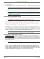
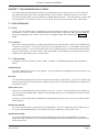
CHAPTER 1 INTRODUCTION
The process supervisor is one part of a complete control system. The entire package is described in the Sys-
tem Configuration Manual HA028314.
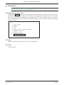
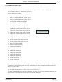
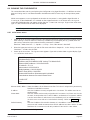
1.1 MANUAL CONTENTS
This manual is divided into the following chapters:
Chapter 1. Introduction
Chapter 2. Installation
Chapter 3. User Interface (explaining the front panel LEDs and switches)
Chapter 4. Start Up (step-by-step instructions on how to start up or re-start the instrument)
Chapter 5. Configuration (how to configure, or more typically re-configure, control strategy and communi-
cations protocols on site, usually to match changes in the plant being controlled). (Initial configu-
ration, to Customer Specification, is normally carried out prior to delivery.)
Chapter 6. Diagnostics (how to diagnose faults that could develop in the instrument, by recognising fault
indications)
Chapter 7. Task Organisation and tuning
Chapter 8. Service
Chapter 9. Technical Specification and order codes
Annex A Configuration (Full configuratioln)
1.2 OTHER INFORMATION SOURCES
For details of (LIN) based function blocks, their parameters and input/output connections refer to the LIN
blocks reference section of the LIN product manual (HA082375U003) which explains how control strategy
LIN blocks are selected, interconnected etc. The creation and monitoring of databases and communications
configurations is described in the Eurotherm Project studio documentation. The configuration of Sequential
Function Charts (SFCs) is described in the LINtools Online help file (RM263001U055) to be found in ‘on-line
books’ in the LINtools application directory. Modbus and Profibus implementations are discussed in the Com-
munications Manual (HA028014).
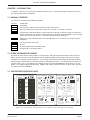
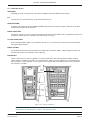
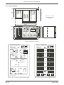
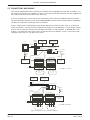
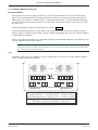
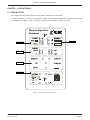
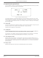
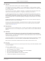
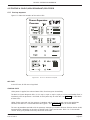
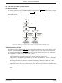
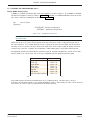
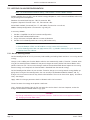
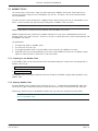
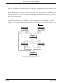
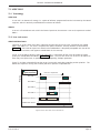
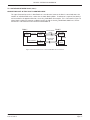
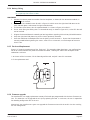
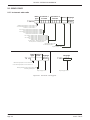
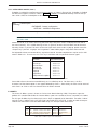
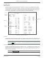
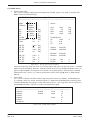
1.3 THE PROCESS SUPERVISOR UNITS
Figure 1.3 Connect module (left) and dual processor modules (centre and right) on the backplane
Process supervisor
Processor
P o w e r
AB
int ext
A l a r ms
r l2
r l1
battery
24V
Co mms
i /o
system
AB t x r x
ex p 2
e x p 1
pr i m a r y
sync
desync
cha ngeov er
standb y
Restart
hot
hot/cold
cold
test
hal t
w d o g
d u p l e x
config
An Invensys company
Process supervisor
Processor
P o w e r
AB
int ext
A l a r ms
r l2
r l1
battery
24V
Co mms
i /o
system
AB t x r x
e x p 2
e x p 1
pr i m a r y
sync
desync
cha ngeov er
standb y
Restart
hot
hot/cold
cold
test
hal t
w d o g
d u p l e x
config
An Invensys company
e
EUROTHERM
Process supervisor
Connect
e
EUROTHERM
i n out
i n out
i n out
i n out
AB
i n out
i n out
i n out
i n out
AB
e x p 2
e x p 1
i/ oB
i /o A
system
r l1 r l2
w d o g batt
a l a r m s
r l1 r l2
w d o g batt
ABAB
++
--
24V
++
--
24V
left processor right processor
+
+
e
EUROTHERM

PROCESS SUPERVISOR HANDBOOK
Chapter 1
Page 1-2
HA028225
Issue 8 Feb 12
1.3.1 Typical applications
The process supervisor is designed to control processing plants using distributed input/output modules, inter-
connected using networks. A number of process supervisors can be networked together, allowing thousands
of I/O points to be monitored and controlled.
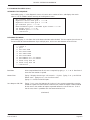
1.3.2 Features
The main features of the process supervisor are as follows
LIN
A LIN-based network using either ALIN or ELIN. This allows communications with I/O modules and the wider
network via either a ‘daisy-chain’ configuration (ALIN only) or a central ALIN or ELIN ‘hub’. See Chapter 2,
figure 2.5.
MODBUS
The Unit supports Modbus comms via the connect module exp1 (master) and exp 2 (slave) ports if so config-
ured. Modbus-tcp-slave is also supported.
PROFIBUS.
The Unit supports Profibus communications via the connect module i/oB port.
REDUNDANT PROCESSOR MODULES
The processors can be set up for redundant or non-redundant operation. When operating in redundant
(duplex) mode, a high speed data link (ICM) between the primary and secondary processor units provides
exact tracking of the control database, allowing bumpless takeover by the secondary unit should the primary
processor fail.
Note: See the ‘Important Information’ leaflet (HA028256) for any backwards compatibility details.
AUTOMATIC TAKE-OVER
Takeover of control by the secondary processor in the event of primary failure is automatic, with no loss of
I/O states and no need to re-initialise I/O points. Revalidation of all attached LIN nodes is automatic.
REDUNDANT POWER SUPPLY CONNECTION
Two independent power connectors for each processor unit, plus external battery for memory backup ensures
full redundancy. An internal battery supports the data in SRAM (if fitted) and the real-time clock for a mini-
mum of 72 hours.
LIVE PROCESSOR REPLACEMENT
Live replacement of a failed processor can be carried out, with no wiring disconnections. The replacement
unit loads its strategy and current status from the active processor. Full hardware and software status indica-
tion allows rapid verification and diagnostics.
DIAGNOSTICS
Automatic health checks, self-testing, and initialisation on power-up.
FRONT PANEL ANNUNCIATION.
Front panel LEDs are provided for communications and processor status. Control switches are also fitted on
each processor module.
CONTINUOUS HEALTH MONITORING
Extensive on-going diagnostics and health monitoring of communications and I/O status.

PROCESS SUPERVISOR HANDBOOK
HA028225
Issue 8 Feb 12
Chapter 1
Page 1-3
1.3.2 FEATURES (Cont.)
WATCHDOG
Watchdog relay for each processor, with Connect module front-panel AND/OR connections.
I/O
Distributed I/O is networked using serial communications links.
CONFIGURATION.
Strategies and sequences configured/downloaded/monitored with Eurotherm Project Studio or the resident
configurator (needs external terminal).
BLOCK STRUCTURE.
Continuous strategies are built up by interconnection of fixed function blocks from a comprehensive library of
analogue and logic elements, common to all LIN based instruments.
ST USER ALGORITHMS
Special ACTION blocks support user-algorithms written in ST (Structured Text) and are well-suited to imple-
ment plant logical devices.
BLOCK SUPPORT
All standard LIN data base function blocks are supported in redundant mode. Special diagnostic blocks are
available for hardware and software status reporting.
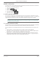
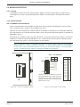
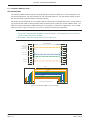
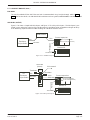
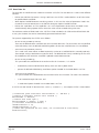
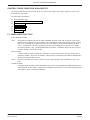
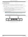
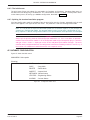
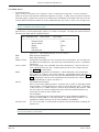
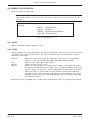
ENCLOSURES
Process supervisor units can be supplied in a range of enclosures, both wall-mounted and floor-standing.
Power supplies, standard terminations, transmitter power supplies, and I/O modules can all be fitted within
these enclosures, and if required, a visual supervisor unit can be door mounted to allow a visual representa-
tion of process variables.
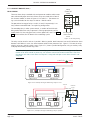
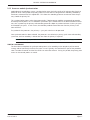
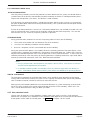
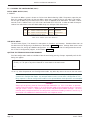
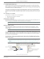
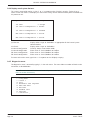
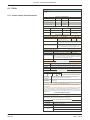
PSUs
Battery
unit
Process
supervisor
I/O
racks
(multiple)
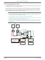
Figure 1.3.2c Typical installations
Note: The process interface i/o modules can be mounted vertically as shown in the sides of the single
bay enclosure, or horizontally as shown in the two-bay version.

PROCESS SUPERVISOR HANDBOOK
Chapter 1
Page 1-4
HA028225
Issue 8 Feb 12
This page is deliberately left blank

PROCESS SUPERVISOR HANDBOOK
HA028225
Issue 8 Feb 12
Chapter 2
Page 2-1
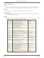
CHAPTER 2 INSTALLATION
This chapter presents safety and EMC information and describes the mechanical and electrical installation of
the instrument. The main topics covered are as follows:
1. Safety & EMC information (section 2.1)
2. Unpacking (section 2.2)
3. Mechanical layout (section 2.3)
4. Set-up switch definition (section 2.4)
5. Connections and wiring (section 2.5)
2.1 SAFETY AND EMC INFORMATION
This unit meets the requirements of the European Directives on Safety and EMC as detailed on the Declara-
tion of conformity IA249986U610, a copy of which appears at the beginning of this manual. It is, however, the
responsibility of the installer to ensure the safety and EMC compliance of any particular installation.
Note: In order to comply with the Low Voltage Directive quoted in the Declaration of Conformity at
the beginning of this manual, neither the positive nor the negative supply line may exceed 40V peak,
with respect to Safety Earth potential.
2.1.1 Installation requirements for EMC
This unit conforms with the essential protection requirements of the EMC Directive 89/336/EEC, amended by
93/68/EEC. It also satisfies the emissions and immunity standards for industrial environments.
To ensure compliance with the European EMC directive certain installation precautions are necessary as fol-
lows:
1 General guidance. For general guidance refer to the EMC Installation Guide (HA025464).
2 Relay outputs. When using relay outputs it may be necessary to fit a filter suitable for suppressing con-
ducted emissions. The filter requirements will depend on the type of load.
3 Routing of wires. To minimise the pick-up of electrical noise, low voltage DC connections and sensor
input wiring should be routed away from high-current power cables. Where it is impractical to do this,
shielded cables should be used, with the shield grounded at both ends.

PROCESS SUPERVISOR HANDBOOK
Chapter 2
Page 2-2
HA028225
Issue 8 Feb 12
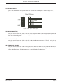
2.1.2 Installation safety requirements
PERSONNEL
Installation must be carried out only by authorized personnel.
HAZARDOUS VOLTAGES
CAUTION
In order to comply with the requirements of BS EN61010, the voltage applied between any I/O terminal
and safety earth may not exceed 30V ac or 50 V dc.
CAUTION
The configuration port is not isolated - see section 2.5.2.
CONDUCTIVE POLLUTION
Electrically conductive pollution (e.g. carbon dust, water condensation) must be excluded from the enclosure
in which the unit is mounted. To ensure the atmosphere is suitable, an air filter should be installed in the air
intake of the enclosure. Where condensation is likely, a thermostatically controlled heater should be included
in the enclosure.
VENTILATION
Ensure that the enclosure or cabinet housing the unit provides adequate ventilation/heating to maintain the
operating temperature of the unit within the limits indicated in the Specification (see Chapter 9).
PRECAUTIONS AGAINST ELECTROSTATIC DISCHARGE
CAUTION
Circuit boards inside the units contain components which can be damaged by static electrical discharge.
Before any circuit board is removed or handled it should be ensured that the handler, the instrument
and the circuit board are all at the same potential.
2.1.3 Keeping the product safe
To maintain the units in a safe condition, observe the following instructions.
MISUSE OF EQUIPMENT
If the equipment is used in a manner not specified in this handbook or by Eurotherm Ltd., the protection pro-
vided by the equipment may be impaired.
SERVICE AND REPAIRS
Except for those parts detailed in Chapter 8, the Process Supervisor has no user-serviceable parts. Contact the
nearest manufacturer’s agent for repair.
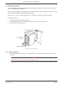
2.2 UNPACKING
The instrument and accessories should be carefully unpacked and inspected for damage. The original pack-
ing materials should be retained in case re-shipment is required. If there is evidence of shipping damage, the
supplier or the carrier should be notified within 72 hours and the packaging retained for inspection by the
manufacturer’s and/or carrier’s representative.
Page is loading ...
Page is loading ...
Page is loading ...
Page is loading ...
Page is loading ...
Page is loading ...
Page is loading ...
Page is loading ...
Page is loading ...
Page is loading ...
Page is loading ...
Page is loading ...
Page is loading ...
Page is loading ...
Page is loading ...
Page is loading ...
Page is loading ...
Page is loading ...
Page is loading ...
Page is loading ...
Page is loading ...
Page is loading ...
Page is loading ...
Page is loading ...
Page is loading ...
Page is loading ...
Page is loading ...
Page is loading ...
Page is loading ...
Page is loading ...
Page is loading ...
Page is loading ...
Page is loading ...
Page is loading ...
Page is loading ...
Page is loading ...
Page is loading ...
Page is loading ...
Page is loading ...
Page is loading ...
Page is loading ...
Page is loading ...
Page is loading ...
Page is loading ...
Page is loading ...
Page is loading ...
Page is loading ...
Page is loading ...
Page is loading ...
Page is loading ...
Page is loading ...
Page is loading ...
Page is loading ...
Page is loading ...
Page is loading ...
Page is loading ...
Page is loading ...
Page is loading ...
Page is loading ...
Page is loading ...
Page is loading ...
Page is loading ...
Page is loading ...
Page is loading ...
Page is loading ...
Page is loading ...
Page is loading ...
Page is loading ...
Page is loading ...
Page is loading ...
Page is loading ...
Page is loading ...
Page is loading ...
Page is loading ...
Page is loading ...
Page is loading ...
Page is loading ...
Page is loading ...
Page is loading ...
Page is loading ...
Page is loading ...
Page is loading ...
Page is loading ...
Page is loading ...
Page is loading ...
Page is loading ...
Page is loading ...
Page is loading ...
Page is loading ...
Page is loading ...
Page is loading ...
Page is loading ...
Page is loading ...
Page is loading ...
Page is loading ...
Page is loading ...
Page is loading ...
Page is loading ...
Page is loading ...
Page is loading ...
Page is loading ...
Page is loading ...
Page is loading ...
Page is loading ...
Page is loading ...
Page is loading ...
Page is loading ...
Page is loading ...
Page is loading ...
Page is loading ...
Page is loading ...
Page is loading ...
Page is loading ...
Page is loading ...
Page is loading ...
Page is loading ...
Page is loading ...
Page is loading ...
Page is loading ...
Page is loading ...
Page is loading ...
Page is loading ...
Page is loading ...
Page is loading ...
Page is loading ...
Page is loading ...
Page is loading ...
Page is loading ...
Page is loading ...
Page is loading ...
Page is loading ...
Page is loading ...
Page is loading ...
-
 1
1
-
 2
2
-
 3
3
-
 4
4
-
 5
5
-
 6
6
-
 7
7
-
 8
8
-
 9
9
-
 10
10
-
 11
11
-
 12
12
-
 13
13
-
 14
14
-
 15
15
-
 16
16
-
 17
17
-
 18
18
-
 19
19
-
 20
20
-
 21
21
-
 22
22
-
 23
23
-
 24
24
-
 25
25
-
 26
26
-
 27
27
-
 28
28
-
 29
29
-
 30
30
-
 31
31
-
 32
32
-
 33
33
-
 34
34
-
 35
35
-
 36
36
-
 37
37
-
 38
38
-
 39
39
-
 40
40
-
 41
41
-
 42
42
-
 43
43
-
 44
44
-
 45
45
-
 46
46
-
 47
47
-
 48
48
-
 49
49
-
 50
50
-
 51
51
-
 52
52
-
 53
53
-
 54
54
-
 55
55
-
 56
56
-
 57
57
-
 58
58
-
 59
59
-
 60
60
-
 61
61
-
 62
62
-
 63
63
-
 64
64
-
 65
65
-
 66
66
-
 67
67
-
 68
68
-
 69
69
-
 70
70
-
 71
71
-
 72
72
-
 73
73
-
 74
74
-
 75
75
-
 76
76
-
 77
77
-
 78
78
-
 79
79
-
 80
80
-
 81
81
-
 82
82
-
 83
83
-
 84
84
-
 85
85
-
 86
86
-
 87
87
-
 88
88
-
 89
89
-
 90
90
-
 91
91
-
 92
92
-
 93
93
-
 94
94
-
 95
95
-
 96
96
-
 97
97
-
 98
98
-
 99
99
-
 100
100
-
 101
101
-
 102
102
-
 103
103
-
 104
104
-
 105
105
-
 106
106
-
 107
107
-
 108
108
-
 109
109
-
 110
110
-
 111
111
-
 112
112
-
 113
113
-
 114
114
-
 115
115
-
 116
116
-
 117
117
-
 118
118
-
 119
119
-
 120
120
-
 121
121
-
 122
122
-
 123
123
-
 124
124
-
 125
125
-
 126
126
-
 127
127
-
 128
128
-
 129
129
-
 130
130
-
 131
131
-
 132
132
-
 133
133
-
 134
134
-
 135
135
-
 136
136
-
 137
137
-
 138
138
-
 139
139
-
 140
140
-
 141
141
-
 142
142
-
 143
143
-
 144
144
-
 145
145
-
 146
146
-
 147
147
-
 148
148
-
 149
149
-
 150
150
-
 151
151
-
 152
152
-
 153
153


Eurotherm T940 Owner's manual
- Category
- Networking
- Type
- Owner's manual
- This manual is also suitable for
Ask a question and I''ll find the answer in the document
Finding information in a document is now easier with AI
Related papers
-
Eurotherm PC3000 Owner's manual
-
-
-
-
-
-
-
-
-
Other documents
-
Moog Syncing Multiple DFAMs Owner's manual
-
Crowcon Detective Net Quick Reference Manual
-
Anybus AB7839 Installation guide
-
IXXAT LIN2CAN Owner's manual
-
ALLEGION RC-04 ISONAS Reader Controll User guide
-
 Rath 2500-92SPRVSR Installation & Operation Manual
-
JCM FREE User guide
-
-
Schneider Electric LUFP7 User manual
-
 iotty Wi-Fi Installation guide

