Page is loading ...

1. Introduction:
The OnQ Combo Modules provide a structured method for distributing telephone service
and RF (cable TV) off air signals throughout a residence. The 6+8 Combo Module, PN
364400-01, also provides a convenient interface between the satellite dish antenna and
two receiver boxes. The Combo Modules can be mounted in OnQ Service Center
Enclosures. The 364400-01 (6+8 Combo Module) is shown right.
2. Description:
The “video” portion has vertical access “F” style fittings for connecting incoming and
outgoing cables. The 364400-01 (6+8 Combo) has a single input, 8 outputs and dual low-
loss DSS feed-throughs for satellite signal distribution. The 364400-02 (6+4 Combo) has a single input, 4 outputs and no
DSS pass throughs. The splitter insertion loss for the -01 version is 12dB and 8dB for the -02 version.
The 1x6 Telecom Module has an eight position 110 punch-down connector for connecting the incoming 4 line service and a
two row, 20-position, posted connector and spade terminal for optional surge protection (P/N 363487-01). There is a vertical
RJ45 jack for test or local handset attachment and a vertical RJ45 jack for the security interface (RJ-31X). Six 8-position 110
punch-down connectors for connecting the outlets to the system are also available. In addition, the module also features a
4- position switch to allow separation of the incoming lines from the outlets for testing purposes (auxiliary disconnect). The
switch is also used to activate security options.
NOTE: The OnQ Combo Module has a vertical dimension of 5 inches. A total of 7 inches of enclosure space is
required for coax cabling.
3. Installation
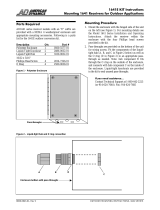
A. Mounting in enclosure (refer to Figure 2).
1) Align tabs on the module with slots on rail enclosure.
2) Insert tabs by angling module away from the back of the enclosure.
3) Rotate the module and insert fasteners on module into corresponding holes on
rail of enclosure. (Plunger must be in a pulled position for fastener to engage
hole.)
4) Push plunger in to lock module in place. Pull on module to ensure module is
locked properly in place.
B. Service Connection, Video Portion (refer to Figure 3, page 2).
1) Identify incoming service cable(s) and route to “Cable In” or “DSS” fitting(s) on
module.
2) Attach an RG-6 “F” connector to the cable. Connect to fitting on module and
finger-tighten.
C. Outlet Drop Connections
1) Identity cables from the outlets and route to appropriate fittings.
2) Attach an RG-6 “F” connector to the cable. Connect to fitting on module and finger-
tighten.
NOTE: Do not bend cable in less than a 2 inch radius.
NOTE: Cables should all be marked to provide identification. Record room locations for cables to the
outlets.
D. Incoming Service Cable Installation, Telecom Portion
1) Identify incoming service cable and route to “Line In” 110 punch-down block. In routing cable, allow slack for
bundling to the side and avoiding other cable terminations. Trim cable about 2 inches beyond connector.
2) Strip off approximately 4 inches of the outer jacket using OnQ strip tool (P/N 363292-01) or equivalent.
3) Position pairs over color-coded slots on the connector. See Figure 4.
Note: Do not untwist pairs.
Note: White wires may not have color trace stripe. Keep white wire paired with appropriate colored wire based on
twist.
OnQ Technologies, Inc.
P.O. Box 60907
Harrisburg, PA 17106-0907
800-321-2343
www.onqtech.com
Installation/Instruction Sheet
OnQ Combo Modules
IS-0096 Rev. A
IS-0096 Rev. A Page 1 of 2
Ref. P/N 363605-96
Figure 2

4) Without untwisting cable, position the wires in individual
slots per Figure 4.
5) Punch-down and trim wires using OnQ punch-down tool
(P/N 363293-01) or equivalent.
6) Remove excess wire and tug slightly on cable to ensure
wire is securely installed in connector.
E. Outlet cable termination
1) Identify outlet cable and route to numbered 110 punch-
down blocks. In routing cable allow slack for bundling to the
side and avoiding other cable terminations. Trim cable about
2 inches beyond connector.
2) Strip off approximately 4 inches of the outer jacket using
OnQ strip tool (P/N 363292-01) or equivalent.
3) Position pairs over color-coded slots on the connector.
See Figure 4.
4) Without untwisting cable, position the wires in individual
slots per Figure 4.
5) Punch-down and trim wires using OnQ punch-down tool
(P/N 363293-01) or equivalent.
6) Remove excess wire and tug slightly on cable to ensure wire is securely installed
in connector.
7) Record room name/number to connector number on wire layout label of enclosure.
8) Repeat until all outlets are connected
Note: To complete proper cross connect install a CAT5 jumper (P/N 363201-27).
F. Securing Cables
After all cables are connected to the module, the cables should be bundled and
grouped to allow ease of maintenance. Wire management straps (P/N 363491-01),
may be used to bundle cable.
4. Testing
A. To test the outlet wiring from the Telecom Module to the wall outlets, turn all
switches on “Test Switch” to “OFF”. Insert line tester into RJ45 jack labeled
“Outlet Test”. Perform check at each wall outlet.
B. To reset module to normal operation, ensure all switches are set to the “ON”
position.
5. Other Applications
A. Security Interface (refer to Figure 5 for Pin Out)
1) To enable line seizure and dial out capability to most security systems, connect the RJ31X
cable (supplied with the security system) to the RJ45 “Security” jack on the module. TURN
OFF Line 1 to activate security link. Connect the other end to the security system as outlined
in the security system installation instructions.
2) To disable security, remove plug from “security” jack and set line 1 to “ON”.
B. Surge Protection
See instructions supplied with Surge Suppressor Unit (P/N 363487-01).
OnQ Technologies, Inc.
P.O. Box 60907
Harrisburg, PA 17106-0907
800-321-2343
www.onqtech.com
Installation/Instruction Sheet
OnQ Combo Modules
IS-0096 Rev. A
IS-0096 Rev. A Page 2 of 2
Ref. P/N 363605-96
Figure 4
Figure 3
-01 as shown
Figure 5
/