Agilent Technologies E3632A User manual
- Category
- Power supply units
- Type
- User manual

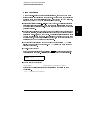
User’s Guide

Agilent E3632A
DC Power Supply

2
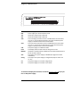
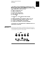
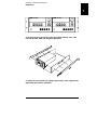
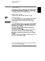
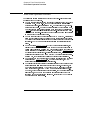
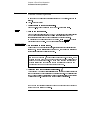
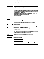
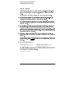
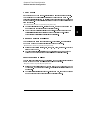
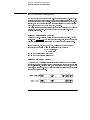
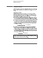
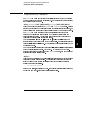
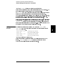
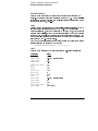
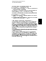
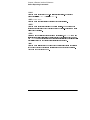
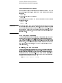
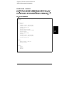
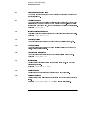
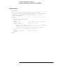
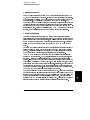
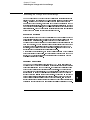
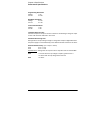
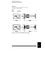
The Front Panel at a Glance
1 15V/7A range selection key
2 30V/4A range selection key
3 Overvoltage protection key
4 Overcurrent protection key
5 Display limit key
6 Recall operating state key
7 Store operating state/Local key
8 Error/Calibrate key
9 I/O Configuration/Secure key
10 Output On/Off key
11 Control knob
12 Resolution selection keys
13 Voltage/current adjust selection key

3
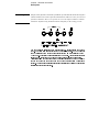
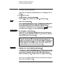
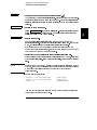
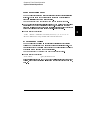
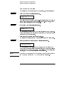
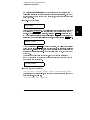
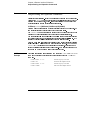
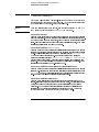
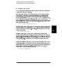
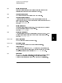
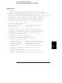
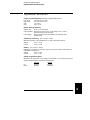
1 15V/7A range selection key Selects the 15V/7A range and allows the full rated output
to 15V/7A.
2 30V/4A range selection key Selects the 30V/4A range and allows the full rated output
to 30V/4A.
3 Overvoltage protection key Enables or disables the overvoltage protection function,
sets trip voltage level, and clears the overvoltage condition.
4 Overcurrent protection key Enables or disables the overcurrent protection function,
sets trip current level, and clears the overcurrent condition.
5 Display limit key Shows voltage and current limit values on the display and allows
knob adjustment for setting limit values.
6 Recall operating state key Recalls a previously stored operating state from location
‘‘1’’, ‘‘2’’, or ‘‘3’’.
7 Store operating state / Local key
1
Stores an operating state in location ‘‘1’’, ‘‘2’’, or
‘‘3’’ / or returns the power supply to local mode from remote interface mode.
8 Error / Calibrate key
2
Displays error codes generated during operation, self-test and
calibration / or enables calibration mode (the power supply must be unsecured before
performing calibration). See Service Guide for more details on calibration.
9 I/O Configuration / Secure key
3
Configures the power supply for remote interfaces
/ or secure or unsecure the power supply for calibration. See Service Guide for more
details on how to secure or unsecure the power supply.
10 Output On/Off key Enables or disables the power supply output. This key toggles
between on and off.
11 Control knob Increases or decreases the value of the blinking digit by turning
clockwise or counter clockwise.
12 Resolution selection keys Move the blinking digit to the right or left.
13 Voltage/current adjust selection key Selects the knob control function for voltage
or current adjustment.
1
2
3

4
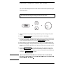
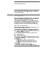
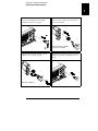
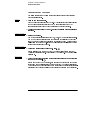
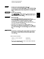
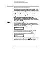
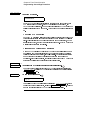
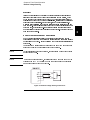
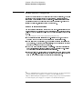
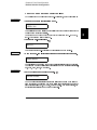
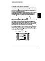
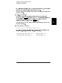
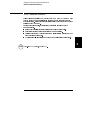
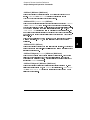
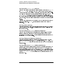
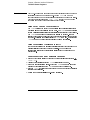
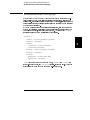
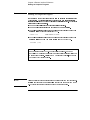
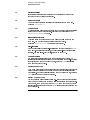
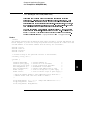
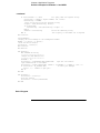
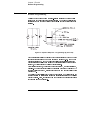
Front-Panel Voltage and Current Limit Settings
You can set the voltage and current limit values from the front panel using the
following method.
1 Select the desired range using the range selection keys after turning on the power
supply.
2 Press the key to show the limit values on the display.
3 Move the blinking digit to the appropriate position using the resolution selection keys
and change the blinking digit value to the desired voltage limit by turning the control
knob. If the display limit times out, press the
key again.
4 Set the knob to current control mode using the voltage/current adjust selection key.
5 Move the blinking digit to the appropriate position using the resolution selection keys
and change the blinking digit value to the desired current limit by turning the control
knob.
6 Press the key to enable the output. After about 5 seconds, the
display will go to output monitoring mode automatically to display the voltage and
current at the output or the display will go to output monitoring mode immediately by
pressing the
key again.
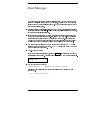
Note
Use the voltage/current adjust selection key, the resolution selection keys, and
the control knob to change the voltage and current limit values.
Display Limit
Display Limit
Output On/Off
Output On/Off

5
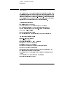
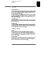
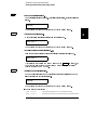
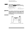
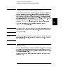
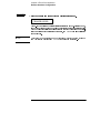
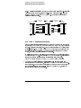
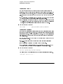
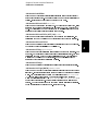
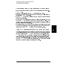
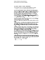
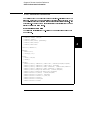
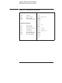
Display Annunciators
Adrs Power supply is addressed to listen or talk over a remote interface.
Rmt Power supply is in remote interface mode.
15V Shows the 15V/7A range is selected.
30V Shows the 30V/4A range is selected.
OVP The overvoltage protection function is enabled when the annunciator
turns on or the overvoltage protection circuit has caused the power
supply to shutdown when the annunciator blinks.
OCP The overcurrent protection function is enabled when the annunciator
turns on or the overcurrent protection circuit has caused the power
supply to shutdown when the annunciator blinks.
CAL The power supply is in calibration mode.
Limit The display shows the limit values of voltage and current.
ERROR Hardware or remote interface command errors are detected and the error
bit has not been cleared.
OFF The output of the power supply is disabled (See page 52 for more
information).
Unreg The output of the power supply is unregulated (output is neither CV
nor CC).
CV The power supply is in constant voltage mode.
CC The power supply is in constant current mode.
To review the display annunciators, hold down key as you
turn on the power supply.
Display Limit

6
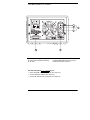
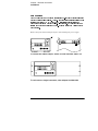
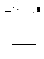
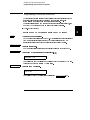
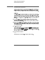
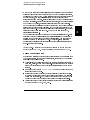
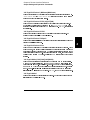
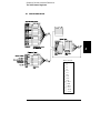
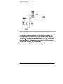
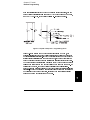
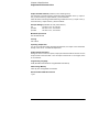
The Rear Panel at a Glance
Use the front-panel key to:
• Select the GPIB or RS-232 interface (see chapter 3).
• Set the GPIB bus address (see chapter 3).
• Set the RS-232 baud rate and parity (see chapter 3).
1 Power-line voltage setting
2 Power-line fuse-holder assembly
3 AC inlet
4 Power-line module
5 GPIB (IEEE-488) interface connector
6 RS-232 interface connector
I/O Config

7
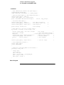
In This Book
General Information
Initial Operation
Front-Panel Operation
Remote Interface Reference
Error Messages
Application Programs
Tutorial
Specifications

8


1
General Information

14
General Information
Safety Considerations

Chapter 1 General Information
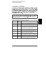
Options and Accessories
15
1
Options and Accessories
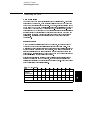
Option Description
0EM 115
0E3
0E9
1CM
0L2
Agilent No. Description
10833A
10833B
34398A
34399A

Chapter 1 General Information
Description
16
Description

Chapter 1 General Information
Description
17
1
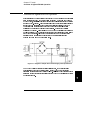
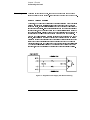
Warning Floating the power supply output more than ±60 Vdc from the chassis presents an
electric shock hazard to the operator. Do not float the outputs more than ±60 Vdc
when metal shorting bars without insulation are used to connect the (+) output to the
(+) sense and the (-) output to the (-) sense terminals.

Chapter 1 General Information
Description
18
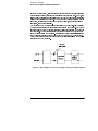
Warning Outputs can be floated to maximum of ±240 Vdc provided that the metal shorting bars
without insulation are either replaced with insulated conductors or they are removed
from the terminals so there is no operator access to the output conductors without
insulation. All field wiring insulation must be adequate for the voltage present.

Chapter 1 General Information
Installation
19
1
Installation
Page is loading ...
Page is loading ...
Page is loading ...
Page is loading ...
Page is loading ...
Page is loading ...
Page is loading ...
Page is loading ...
Page is loading ...
Page is loading ...
Page is loading ...
Page is loading ...
Page is loading ...
Page is loading ...
Page is loading ...
Page is loading ...
Page is loading ...
Page is loading ...
Page is loading ...
Page is loading ...
Page is loading ...
Page is loading ...
Page is loading ...
Page is loading ...
Page is loading ...
Page is loading ...
Page is loading ...
Page is loading ...
Page is loading ...
Page is loading ...
Page is loading ...
Page is loading ...
Page is loading ...
Page is loading ...
Page is loading ...
Page is loading ...
Page is loading ...
Page is loading ...
Page is loading ...
Page is loading ...
Page is loading ...
Page is loading ...
Page is loading ...
Page is loading ...
Page is loading ...
Page is loading ...
Page is loading ...
Page is loading ...
Page is loading ...
Page is loading ...
Page is loading ...
Page is loading ...
Page is loading ...
Page is loading ...
Page is loading ...
Page is loading ...
Page is loading ...
Page is loading ...
Page is loading ...
Page is loading ...
Page is loading ...
Page is loading ...
Page is loading ...
Page is loading ...
Page is loading ...
Page is loading ...
Page is loading ...
Page is loading ...
Page is loading ...
Page is loading ...
Page is loading ...
Page is loading ...
Page is loading ...
Page is loading ...
Page is loading ...
Page is loading ...
Page is loading ...
Page is loading ...
Page is loading ...
Page is loading ...
Page is loading ...
Page is loading ...
Page is loading ...
Page is loading ...
Page is loading ...
Page is loading ...
Page is loading ...
Page is loading ...
Page is loading ...
Page is loading ...
Page is loading ...
Page is loading ...
Page is loading ...
Page is loading ...
Page is loading ...
Page is loading ...
Page is loading ...
Page is loading ...
Page is loading ...
Page is loading ...
Page is loading ...
Page is loading ...
Page is loading ...
Page is loading ...
Page is loading ...
Page is loading ...
Page is loading ...
Page is loading ...
Page is loading ...
Page is loading ...
Page is loading ...
Page is loading ...
Page is loading ...
Page is loading ...
Page is loading ...
Page is loading ...
Page is loading ...
Page is loading ...
Page is loading ...
Page is loading ...
Page is loading ...
Page is loading ...
Page is loading ...
Page is loading ...
Page is loading ...
Page is loading ...
Page is loading ...
Page is loading ...
Page is loading ...
Page is loading ...
Page is loading ...
Page is loading ...
Page is loading ...
Page is loading ...
Page is loading ...
Page is loading ...
Page is loading ...
Page is loading ...
Page is loading ...
Page is loading ...
Page is loading ...
Page is loading ...
Page is loading ...
Page is loading ...
Page is loading ...
Page is loading ...
Page is loading ...
Page is loading ...
Page is loading ...
Page is loading ...
Page is loading ...
Page is loading ...
-
 1
1
-
 2
2
-
 3
3
-
 4
4
-
 5
5
-
 6
6
-
 7
7
-
 8
8
-
 9
9
-
 10
10
-
 11
11
-
 12
12
-
 13
13
-
 14
14
-
 15
15
-
 16
16
-
 17
17
-
 18
18
-
 19
19
-
 20
20
-
 21
21
-
 22
22
-
 23
23
-
 24
24
-
 25
25
-
 26
26
-
 27
27
-
 28
28
-
 29
29
-
 30
30
-
 31
31
-
 32
32
-
 33
33
-
 34
34
-
 35
35
-
 36
36
-
 37
37
-
 38
38
-
 39
39
-
 40
40
-
 41
41
-
 42
42
-
 43
43
-
 44
44
-
 45
45
-
 46
46
-
 47
47
-
 48
48
-
 49
49
-
 50
50
-
 51
51
-
 52
52
-
 53
53
-
 54
54
-
 55
55
-
 56
56
-
 57
57
-
 58
58
-
 59
59
-
 60
60
-
 61
61
-
 62
62
-
 63
63
-
 64
64
-
 65
65
-
 66
66
-
 67
67
-
 68
68
-
 69
69
-
 70
70
-
 71
71
-
 72
72
-
 73
73
-
 74
74
-
 75
75
-
 76
76
-
 77
77
-
 78
78
-
 79
79
-
 80
80
-
 81
81
-
 82
82
-
 83
83
-
 84
84
-
 85
85
-
 86
86
-
 87
87
-
 88
88
-
 89
89
-
 90
90
-
 91
91
-
 92
92
-
 93
93
-
 94
94
-
 95
95
-
 96
96
-
 97
97
-
 98
98
-
 99
99
-
 100
100
-
 101
101
-
 102
102
-
 103
103
-
 104
104
-
 105
105
-
 106
106
-
 107
107
-
 108
108
-
 109
109
-
 110
110
-
 111
111
-
 112
112
-
 113
113
-
 114
114
-
 115
115
-
 116
116
-
 117
117
-
 118
118
-
 119
119
-
 120
120
-
 121
121
-
 122
122
-
 123
123
-
 124
124
-
 125
125
-
 126
126
-
 127
127
-
 128
128
-
 129
129
-
 130
130
-
 131
131
-
 132
132
-
 133
133
-
 134
134
-
 135
135
-
 136
136
-
 137
137
-
 138
138
-
 139
139
-
 140
140
-
 141
141
-
 142
142
-
 143
143
-
 144
144
-
 145
145
-
 146
146
-
 147
147
-
 148
148
-
 149
149
-
 150
150
-
 151
151
-
 152
152
-
 153
153
-
 154
154
-
 155
155
-
 156
156
-
 157
157
-
 158
158
-
 159
159
-
 160
160
-
 161
161
-
 162
162
-
 163
163
-
 164
164
-
 165
165
-
 166
166
-
 167
167
-
 168
168
-
 169
169
-
 170
170
-
 171
171
-
 172
172


Agilent Technologies E3632A User manual
- Category
- Power supply units
- Type
- User manual
Ask a question and I''ll find the answer in the document
Finding information in a document is now easier with AI
Related papers
-
Agilent Technologies Video Gaming Accessories E3632A User manual
-
Agilent Technologies E4356A User manual
-
-
-
-
-
-
-
Agilent Technologies n3306a User manual
-
Other documents
-
B&K Precision PVS10005 User manual
-
 Pendulum CNT-91R User manual
-
Fluke Analizadores de calidad eléctrica de alta precisión Norma de Norma 4000 User manual
-
-
-
-
National Instruments GPIB-COM User manual
-
 B & K Precision Model XLN10014-GL User manual
-
Philips PM2812 User manual
-
Anritsu MG369 C Series Programming Manual

