Page is loading ...

5-5/8" REF.
T064.60X
M968836 Rev.1.4
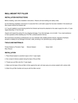
To assure proper positioning in relation to wall, note
roughing-in dimensions.
ROUGHING-IN DIMENSIONS
Certified to comply with ANSI A112.18.1
Installation
Instructions
THREADED INLETS (STOPS)
INLETS
1/2" NPT
5-5/8"
1-3/4"
OUTLETS 1/2" NPT
5-5/8"
Recommended Tools
Flat Blade Screwdriver
Adjustable Wrench
Channel Locks
Plumbers' Putty or Caulking
Phillips Screwdriver
1-5/8" TO 3-1/4"
BOTTOM OF
TUB
74" FOR
HEAD CLEARANCE
1/2" NPT
FINISHED WALL
OPTIONAL TO
FINISHED FLOOR
USUALLY BETWEEN
80'' AND 86'
8-1/8" REF.
4"
6-3/4"
1/2" NPT
1/2" REF.
18"
OPTIONAL
"SEE ILLUSTRATION"
TOP OF
TUB RIM
SHW
TUB
Pipe Wrench
BATH/SHOWER TRIM KIT WITH DIVERTER
7-1/4" D.
2-3/8"
SERIN
™
To ensure that your installation proceeds smoothly-please read these
instructions carefully before you begin.
Thank you for selecting American-Standard...the benchmark
of fine quality for over 100 years.
To ensure that your installation proceeds smoothly--please
read these instructions carefully before you begin.
DO: SIMPLY RINSE THE PRODUCT CLEAN WITH
CLEAR WATER. DRY WITH A SOFT COTTON
FLANNEL CLOTH.
DO NOT: DO NOT CLEAN THE PRODUCT WITH
SOAPS, ACID, POLISH, ABRASIVES, HARSH
CLEANERS, OR A CLOTH WITH A COARSE
SURFACE.
CARE INSTRUCTIONS:

1
INSTALL DIVERTER
When finished tiling the wall, remove PLASTER GUARD (1).
Remove two screws that secure the DIVERTER LID (2) and
remove Lid. Inspect the inside surface of diverter port.
Diverter port must be free of any dirt. Clean if necessary.
Install DIVERTER (3) with SCREWS (4) removed with
DIVERTER LID (2).
Operate DIVERTER (3). DIVERTER (3) should slide in
and out smoothly.
1
4
3
DIVERTER
PORT
2
INSTALL VALVE TRIM
Figure 1. Push CAP (1) over VALVE CARTRIDGE (2) until
seated against stop. Push CAP (3) over DIVERTER (4) until
seated against stop.
Figure 2. Push ESCUTCHEON HOLDER (5) onto CAP (1)
and attach to valve body with SCREWS (6). Mount
ESCUTCHEON SUPPORT (7) to ESCUTCHEON HOLDER (5)
with SCREWS (8).
Figure 3. Install ESCUTCHEON (9) onto CAP (1) and push
flush against finished wall. Escutcheon (9) will snap fit onto
ESCUTCHEON SUPPORT (7).
1
2
3
4
1
1
Figure 1.
Figure 2.
Figure 3.
2
M968836 Rev.1.4
5
6
9
7
8
7

5
Unthread LEVER HANDLE, loosen SET SCREW and pull
HANDLE off valve stem.
To remove Escutcheon assembly reverse steps in Step 3.
TO GAIN ACCESS TO VALVE FOR SERVICING
Remove CARTRIDGE (1) by removing CARTRIDGE SCREWS (2).
Remove three SCREWS (3) from FIXATION RING (4) and pull
out PRESSURE BALANCING (5) unit.
Clean SEALS (9) on base of CARTRIDGE (1). Check base of
PRESSURE BALANCING UNIT (5) and clean O-RINGS (6). Remove
CAPS (7) and check O-RINGS on inside of CAPS (7). Clean inside
sealing surfaces of VALVE BODY (8).
Re-assemble PRESSURE BALANCING UNIT (5) and CARTRIDGE (1).
Tighten all screws.
Turn on water supply and see above for installing TRIM and HANDLE.
VALVE LEAKS WHEN SHUT OFF
BACK TO BACK INSTALLATION
ROTATE 180˚
BACK TO BACK INSTALLATION
Remove PRESSURE BALANCE UNIT (5). Rotate PRESSURE BALANCE UNIT (5) 180˚ so that the inlets face up
and the large outlet port faces down.
Push PRESSURE BALANCE UNIT (5) in casting make sure inlets line up with holes in bottom of casting.
Top flange should butt up against top of casting.
Reassemble FIXATION RING (4) and CARTRIDGE (1).
Remove PRESSURE BALANCE UNIT (5). Remove CAPS (7)
and clean valve thoroughly.
Examine balancing unit and check condition of O-ring on end of
piston. Piston should move back and forth. Order Repair
Part M952100-0070A if balancing unit is defective.
Replace CAPS (7) and install PRESSURE BALANCE UNIT (5).
Make sure inlets line up with two holes in bottom of casting.
Top flange should butt-up against top of casting.
UNABLE TO MAINTAIN CONSTANT TEMPERATURE
1
2
9
5
5
7
8
6
4
3
INLETS
LARGE OUTLET
PIPE
PLUG
4
INSTALL HANDLE, DIVERTER KNOB, TUB
SPOUT AND SHOWER
5
6
Remove pipe cap and plug from shower and tub
rough piping.
Install SPOUT ESCUTCHEON (9) onto TUB SPOUT (10).
Apply sealant or Teflon tape to threads of tub filler
nipple. Thread TUB SPOUT (10) onto tub nipple.
Install SHOWER ESCUTCHEON (11) onto SHOWER
ARM (12). Apply sealant or Teflon tape to threads on
both ends of SHOWER ARM (12) and thread longer
leg of SHOWER ARM (12) into shower elbow.
Thread SHOWER HEAD (13) onto SHOWER ARM (12).
ADJUST HOT LIMIT STOP
By restricting HANDLE rotation and limiting the amount of hot
water allowed to mix with the cold, the HOT LIMIT SAFETY
STOP (1) reduces risk of accidental scalding. To set the maximum
hot water temperature of your faucet, all you need to do
is adjust the setting on the HOT LIMIT SAFETY STOP (1).
1
5
1
3
1
1
9
7
5
3
1
0
3
Turn CARTRIDGE STEM (2) to the OFF position (coldest setting)
before making adjustment to HOT LIMIT STOP (1). Use a flat
blade screwdriver to pry free the HOT LIMIT SAFETY STOP (1).
Pull forward and rotate counterclockwise one number to limit hot
water temperature. Use ARROW (3) on CARTRIDGE (4)
and NUMBERS (5) on HOT LIMIT STOP (1) for
indication.
1
5
4
3
2
1
5
1
3
1
1
9
7
5
3
1
1
5
1
3
1
1
9
7
5
3
1
COLDER
(Larger Numbers)
0 1 3 5 7 9 11 13 15
HOTTER
(Smaller Numbers)
0 1 3 5 7 9 11 13 15
1
5
4
3
2
9
13
12
11
2
4
CAUTION: Protect finish on SHOWER HEAD and
ARM when installing.
SHR.
ELBOW
TUB
NIPPLE
M968836 Rev.1.4
Thread DIVERTER KNOB (1) onto diverter stem.
PIPE
CAP
10
Hold ADAPTER (2) onto VALVE STEM (3) and install
ADAPTER SCREW (4) through ADAPTER (2) into
VALVE STEM (3).Tighten ADAPTER SCREW (4) to
secure ADAPTER (2) to VALVE STEM (3).
Install HANDLE BASE (5) onto ADAPTER (2). Insert
SET SCREW (6) into HANDLE BASE (5). Align
HANDLE BASE (4) and tighten with HEX WRENCH
(7) supplied.
1
3
7

A953929-0070A
DIVERTER KIT
M962209-YYY0A
SPOUT KIT
M962495-YYY0A
TUB SPOUT ESCUTCHEON
T064.60X
MODEL NUMBER
A950842-YYY0A
ESCUTCHEON
WITH DIVERTER
SERIN
™
M909917-YYY0A
DIVERTER KNOB
M907053-YYY0A
CAP
M907103-YYY0A
DIVERTER COVER
M968836 Rev.1.4
BATH/SHOWER TRIM KIT
WITH DIVERTER
922388-YYY0A
STREAM STRAIGHTENER
M962818-YYY0A
DEEP ROUGH KIT
(NOT SHOWN)
A918477-0070A
HANDLE SCREW
M918039-0070A
HANDLE ADAPTER
HOT LINE FOR HELP
For toll-free information and answers to your questions, call:
1 (800) 442-1902
Weekdays 8:00 a.m. to 6:00 p.m. EST
IN CANADA 1-800-387-0369 (TORONTO 1-905-306-1093)
Weekdays 8:00 a.m. to 7:00 p.m. EST
Product names listed herein are trademarks of American Standard Inc.
© AS America, Inc. 2008
IN MEXICO 01-800-839-12-00
CHROME
SATIN NICKEL
002
295
Replace the "YYY" with
appropriate finish code
M953540-YYY0A
SHOWER HEAD
M962493-YYY0A
SHOWER ARM & FLANGE
M962641-0070A
ESCUTCHEON HOLDER
A912632-0070A
O-RING
M962426-YYY0A
HANDLE KIT
/