Page is loading ...

Doc.Ref. No. m83B/QG/101 Issue No.:00 Page 1 of 2
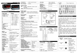
85XX+ Scanner/DAQ
Input
Type
Range
Input
Type
Range
E
-200 to 10 0 0 C
CU53
-210.0 to
210.0°C
J
-20 0 to 12 0 0 C
NI120
-70.0 to
210.0°C
K
-20 0 to 13 7 0 C
-10 to 20
mV
-1999
to 9 9 99
T
-200 t o 400C
0 to 100
mV
B
450 to 1800C
4-20mA
R
0 t o 175 0 C
0 to 20
mA
S
0 t o 175 0 C
0 – 5 V
N
-200 to 1300°C
1 – 5 V
RTD(PT100)
-199.9 to 850.0C
0 – 10V
Table 1.1
SPECIFICATIONS
NO. OF CHANNEL
8 or 16 or 24
ACCURACY
TC/RTD/LINEAR:
+ 0.1% of instrument
range + 1 digit
RESOLUTION
TC(E,J,K,T)/RTD/CU53/NI120:
TC(B,R,S,N):
LINEAR:
ADC: 17 bits
0.1C
1C
1 Count
APPLICABLE STANDARD
DIN (ITS-90) for
Thermocouple and RTD
INPUT TYPE
Refer table 1.1
SAMPLING PERIOD PER
INPUT
50 ms for TC and Linear
Input and 100 ms for
RTD
BURNOUT CURRENT
0.4 µA
MEASUREMENT CURRENT
250 µA
INPUT IMPEDANCE
>1 MΩ for RTD/Voltage
inputs, 250 Ω for
current Input
NMRR
> 40 dB (50/60 Hz)
CMRR
>120 dB (50/60 Hz)
ALLOWABLE WIRING
RESISTANCE FOR RTD
Maximum 15 ohms/wire
(Conductor resistance
between three wires
should be equal).
Digital Input Specification (Optional)*
* With Digital Input, CE marking is not applicable/valid
Digital Output- Relay
NUMBER OF OUTPUTS
8
PURPOSE
Alarm or trip or control or
watchdog output
OUTPUT SIGNAL
Two terminals (C and NO)
RELAY CONTACT
RATING
250 VAC / 30 VDC @ 2A
NUMBER OF RELAY
OPERATION
1 X 10^5 @ rated current
Digital Output- Open Collector (Optional)
NUMBER OF OUTPUTS
24
PURPOSE
Alarm or trip or control or
watchdog output
OUTPUT TYPE
transistor open collector
output selection)
CONTACT RATING
30 V DC,100 mA
Analog Output- Analog Output (Optional)*
NUMBER OF OUTPUTS
8
OUTPUT SIGNAL
0-20 mA, 4-20 mA or 0-5 V,
1-5 V, 0-10 V DC
LOAD RESISTANCE
For current o/p, 550Ω Max.
For Voltage o/p, 3000Ω Min.
OUTPUT ACCURACY
±0.25% of span
* With Analog Output, CE marking is not applicable/valid.
Programming and Setting
KEYPAD
8-keys tactile membrane
keypad
CONFIGURATION
SOFTWARE
All Configurable parameters can
be set through PC Based
software
MEMORY
Non-volatile, restored after
power loss
Communication Specification
NO. OF COMMUNICATION
PORT
2-RS485(COM-1 and
COM-2) . COM2 is
Optional
COMMUNICATION TYPE
Half duplex/Asynchronous
COMMUNICATION
PROTOCOL
MODBUS RTU. All
parameters are
Configurable through
MODBUS Protocol.
MAXIMUM NO. OF UNITS
32
COMMUN. ERROR
DETECTION
CRC Check
PROFIBUS Communication (Optional) *
MODE
Profibus DP Slave
BAUD RATE
9600, 19.2K, 44.45K, 93.75K,
187.5K, 500K, 1.5M, 12M bps
ADDRESS
Configurable through Configuration
Software (0 to 125 Only)
NETWORK
CAPACITY
Multi-drop up to 31 modules, Plus
a host, without a repeater
Up to 125 modules plus a host if
four repeaters are used
COMMUICATION
DISTANCE
Up to 1200 meters without a
repeater using Type A wire
1200m @ 115Kbps or less
1000m @ 187.5Kbps
400m @ 500Kbps
200m @ 1.5Mbps
100m @ 12Mbps
* With Profibus communi. , CE marking is not applicable
HMI Interface (Optional)*
NO. OF COMMUNICATION
PORT
1-RS-232 (HMI)
COMMUNICATION TYPE
Half
duplex/Asynchronous
COMMUNICATION
PROTOCOL
MODBUS RTU
CONNECTABLE NO. OF
UNITS
1
COMMUN. ERROR
DETECTION
CRC Check
Network Connectivity (Optional)
NO. OF COMMUNICATION
PORT
1(RJ-45)
TRANSMISSION SPEED
10 Mbps
NETWORK PROTOCOL
TCP/IP
APPLICATION PROTOCOL
MODNET
Data logging (Optional)
Data logging Memory Type
Flash Memory (32
MB)
Data logging type
Periodic and Event
Periodic Memory Size
25 MB
Event Memory Size
7 MB
RTC Time format
DD/MM/YY –
HH:MM:SS
Periodic Logging sampling
time
1 Second minimum
Event polling time
1 second
USB Port*
1(USB 2.0)
USB Function
For retrieving logged
data only
Max. USB storage device
size
Upto 32 GB
USB Mass storage device
format
FAT16
FAT32
USB fetched data file format
.xls (only)
USB data retrieving option
Full Data Fetch
Fetch Data by time
*With USB port, CE marking is not applicable/valid.
Display Specification
CHANNEL NO
DISPLAY
2-digits, 7-segment, Green , 0.56”
character height
DATA
DISPLAY
4-digits, 7-segment, Red, 0.56’’
character height
PARAMETER
DISPLAY
6-digits, 16-segment Alphanumeric,
Orange LEDs, 0.3” character height
STATUS LEDs
24-Red LEDs for Alarm, 24-Orange
LEDs Control Output, 8-Green LEDs for
Relay, 1-Red LED for Manual mode, 1-
Green for Run mode,1-Red for Fault,
2-Green(Rx) & 2-Red(Tx) for
Communication
Environmental Specification:
AMBIENT TEMPERATURE
-10 to 55°C
HUMIDITY
30% to 95% RH
(Non-Condensing)
TEMPERATURE COEFFICIENT
< 100ppm
WEIGHT
1.25 KG
INSTRUMENT WARM-UP
TIME
<15 mins after power
on
DEGREE OF PROTECTION
IP54 (From Front)
Power Supply Specification
RATED VOLTAGE
85-265VAC-50/60Hz /
100-300VDC or 18-36VDC
POWER CONSUMPTION
Max. 16 VA (85-265 VAC)
and Max. 8 VA (18-36
VDC)
Isolations (Withstanding Voltage)
Between primary terminals* and secondary
terminals**: 1500VAC for 1 minute
Between secondary terminals: 500V AC for 1
minute
* Primary terminals indicate power terminals and
relay output terminals
** Secondary terminals indicate analog input signals,
Digital Contact output terminals, communication
terminals and Ethernet N/W terminal
Insulation Resistance: 20MΩ or more at 500 V DC
Signal Isolation Specifications
Sr.No
Signals
Signal Isolation
1
Power Input
Isolated from other ip/op
terminals and internal circuit
2
Analog Inputs
Not isolated from other analog
i/p terminals & the internal
circuit. But isolated from other
ip/op terminals.
3
RS-485
Communication
Isolated from other ip/op
terminals and internal circuit
4
Ethernet
Communication
Isolated from other ip/op
terminals and internal circuit
5
Relay contacts
Isolated between contact o/p
terminals & from other ip/op
terminals and internal circuit
6
Digital Output
Isolated from other ip/op
terminals and internal circuit
Quick User Guide
85XX+ Scanner/DAQ
NUMBER OF
INPUT
CHANNELS
16
RATED
INPUT
VOLTAGE
12 V DC
(Sink /
Source)
24 V DC
(Sink /
Source)
110 V
DC
(Sink)
220 V
DC
(Sink)
INPUT ON
VDC
≥ 7 V
≥ 15 V
≥ 75 V
≥ 110 V
INPUT OFF
VDC
≤ 4 V
≤ 5 V
≤ 30 V
≤ 50 V
INPUT
CURRENT
4 mA ±
20% /
Ch
4 mA ±
20% /
Ch
2 mA /
Ch
2 mA /
Ch
MAXIMUM
ALLOWABLE
INPUT
VOLTAGE
15 V DC
30 V DC
132 V
DC
250 V
DC
RESPONSE
TIME
50 mSec

Doc.Ref. No. m83B/QG/101 Issue No.:00 Page 2 of 2
Construction, Installation & Wiring
Specification
MATERIAL
Aluminum extrusion
CONSTRUCTION
Panel Mount Top and
Bottom mounting clamps (1
each)
CASE COLOR
Clear Anodized
WEIGHT
1.25 KG
ENCLOSURE
DIMENSION
72mm (W) X 144mm (H) X
165mm (D)
PANEL CUTOUT
68.5mm (W) x 137mm (H)
MOUNTING DETAILS
TERMINAL CONNECTION
DO – RL Relay Terminals: 16
Pre-Feb. Cable
Power Supply: Live (L/+), Neutral(N/-) and Earth
( )
Pre-Feb. Cable
AI-1,2 and 3 Analog Input: 72 or AI-1 Analog
Input: 8 and DI-1 Digital Input: 16
Pre-Feb. Cable
DO – OC Digital Contact Output: 25 or AO – Analog
Contact Output: 16(Optional)
Pre-Feb. Cable
RS-485 Communication: 4
Wire Size: 26- 16AWG
Screw Size: M2.0 Steel Ni Plated
Ethernet Communication: 1
RJ-45 Connector
FRONT PANEL DESCRIPTION
Symbol
Operation
It allows Mode Selection during Run mode,
while it allows saving value of a parameter
inside a mode. When inside any mode, it
allows to enter in sub-mode.
It is used to come out from mode/Sub-
mode. It is also used to escape from edit
mode without saving the respective
parameter.
It is used in increment of value in run mode
and other modes
It is used in decrementing value when run
mode and other modes. It is also used for
shifting a digit while editing of numeric
value.
It allows user to toggle between Auto
Channel Display mode – Manual Channel
Display Mode.
Acknowledge the Alarm During RUN Mode.
Enter into Set Alarm1 and Alarm2 mode
during RUN Mode
When pressed in run mode it will allow the
user to enter into Control Set point Mode
Control Output Operation
Control O/P is the simplest form of temperature control.
The output from the device is either on or off, with no
middle state. For heating control, the o/p is on when the
temperature is below the set point, and off above set point.
Since the temp. crosses the set point to change the o/p
stage, the process temp. will be cycling continually, going
from above set point to below, and back above. In cases
where this cycling occurs rapidly, and to prevent contactors
and valves from getting damaged, on-off differential, or
Hysteresis is added to the control operations.
This Hysteresis assures, if temp. goes below set point by a
certain amount before then only o/p will turn off or on
again. On-Off Hysteresis prevents the o/p from chattering
or making fast, continual switches if the cycling above and
below the set point occurs very rapidly. Once Process value
reaches down to set point-Hysteresis value relay will be
energized and it will be on until process value goes up
towards Set point.
BASIC DO (DIGITAL OUTPUT) FUNCTION
WATCHDOG TIMER / OUTPUT OPERATION
The WDT, when enabled, operates from the internal Low-
Power RC (LPRC) Oscillator clk source. The WDT can be
used to detect system software malfunctions by resetting
the device if the WDT is not cleared periodically in
software. If malfunctioning of device persist even after
watchdog reset device will go into shutdown mode followed
by error messages on display as per Error! Reference
source not found..
Device Fault can be monitored by a failsafe relay o/p which
is mapped for watchdog o/p. When WDT is disable device
will continue to work with fault. The Fault LED will be on in
this condition.
Error Messages
Fault
Error 1
CPU card EEPROM failure
Error 2
SC 1 card ADC failure
Error 3
SC 1 card EEPROM failure
Error 4
SC 2 card ADC failure
Error 5
SC 2 card EEPROM failure
Error 6
SC 3 card ADC failure
Error 7
SC 3 card EEPROM failure
Error 8
CPU card Controller Hang –
failure
Error 9
Communication between CPU and
Display card Failure
ALARM OUTPUT
Every single channel can have maximum 3 set points. 2 for
Alarm outputs(1 for Alarm 1 Set Point and 1 for Alarm 2
Set Point) and 1 for Control Set Point, totaling 48 alarm
outputs and 24 control outputs for 24 number of channels.
Control Outputs are Optional.
8 Relays and/or 24 Open Collectors can be used as DO.
All Digital Outputs are Optional.
Following tables shows Alarm Output , control output
and digital output operation.
For operation manual please visit www.masibus.com
Specifications are subject to change without notice due to
continuous improvements.
Masibus Automation And Instrumentation Pvt. Ltd.
B-30, GIDC Electronics Estate, Sector-25, Gandhinagar-
382044, Gujarat, India.
Tel:+91 79 23287275-79 Fax: +91 79 23287281
Web:www.masibus.com Email:[email protected]
/