Page is loading ...

NH
Series
Installation and
Operation Manual
Includes installation, operation
maintenance and troubleshooting
information for your NHRS Resistive
Element Steam Humidifier
2530618-J | 10 NOV 2014
Important: Read and save these instructions. This guide to be left with equipment.

Thank you for choosing NORTEC.
Proprietary Notice
This document and the information disclosed herein are proprietary data of Nortec Humidity Ltd. Neither this
document nor the information contained herein shall be reproduced, used, or disclosed to others without the
written authorization of Nortec Humidity Ltd., except to the extent required for installation or maintenance of
recipient’s equipment.
Liability Notice
Nortec does not accept any liability for installations of humidity equipment installed by unqualified personnel,
or the use of parts/components/equipment that are not authorized or approved by Nortec.
Copyright Notice
Copyright 2014, Nortec Humidity Ltd. All rights reserved.
INSTALLATION DATE (MM/DD/YYYY)
MODEL #
SERIAL #

Contents
1 Introduction
2 Receiving and Unpacking
3 Humidifier Components
4 Description of Components
5 NHRS Models
8 Installation
9 Typical Humidifier Installation
10 Location
12 Mounting with Keyholes
13 Plumbing
14 Steam Distributor
15 Steam Lines and Condensate
Return
21 Electrical
22 External Controls
29 Optional Outdoor Temperature
Setback Sensor
30 Remote Fault Option Wiring
31 Options and Accessories
33 Start Up
34 Installation Check
36 Start Up Procedure
38 Information Screens
45 How the Humidifier Works
47 Selecting an RH Setpoint
48 Maintenance and
Servicing
52 Troubleshooting
53 General Troubleshooting
55 Wiring Diagrams
57 Start Up Checklists
60 Maintenance Checklists
61 Spare Parts
62 NHRS Plumbing Parts
64 NHRS Electrical Parts
66 Warranty

1 | Introduction
Introduction
CAUTION: Servicing
Disconnect main power before any servicing.
The plumbing and electrical compartments contain high voltage components and
wiring. Access should be limited to authorized personnel only.
During and following operation of the humidifier, the steam and components in
contact with the steam such as the cylinder, blower pack, steam lines, steam
distributors, and condensate lines can become hot and can burn if touched.
Nortec Humidity Ltd. does not accept any liability for installations of humidity
equipment installed by unqualified personnel or the use of parts/components /
equipment that are not authorized or approved by Nortec Humidity Ltd.
CAUTION: Electrical
All electrical work should be done according to local electrical code.
Electrical connection to be performed by a licensed electrician.
CAUTION: Plumbing
Plumbing to be performed by a licensed plumber.
Drain water from humidifier can be very hot. Do not drain to public sink.
All plumbing work should be done according to local plumbing code.
CAUTION: Installation
Do not mount on hot surfaces.
Do not mount in area where freezing can occur.
Do not mount on vibrating surface.
Do not mount on floor.
The NHRS produces steam at atmospheric pressure, no devices which could block
steam output should be connected to the steam outlet.
Steam lines must be installed so that no restriction can produce backpressure in
the humidifier. Failure to follow installation instructions will result in improper
operation and could void warranty.
Regardless of selecting On/Off or modulating control method, NORTEC humidifiers
must have a closed circuit across the On/Off security loop control terminal to
operate. NORTEC highly recommends the use of a high limit humidistat and an air
proving switch in series for this function.

Introduction | 2
Receiving and Unpacking
1 Check packing slip to ensure ALL material has been delivered.
2 All material shortages are to be reported to NORTEC within 48 hours from receipt of goods.
NORTEC assumes no responsibility for any material shortages beyond this period.
3 Inspect shipping boxes for damage and note damages on shipping waybill accordingly.
4 After unpacking, inspect equipment for damage. If damage is found, notify the shipper
promptly.
5 All NORTEC products are shipped on a Free-On-Board (FOB) factory basis. Any and all
damage, breakage or loss claims are to be made directly to the shipping company.
Before Installation
1 Ensure that available voltage and phase corresponds with humidifier voltage and phase as
indicated on humidifier specification label.
2 Ensure that the dedicated external fuse disconnect is of sufficient size to handle the rated
amps as indicated on the specification label. Refer to local codes.
3 Report any discrepancy immediately to the site engineer.
4 Ensure sufficient clearances will be available as described on pages 10 and 11.
5 Ensure steam lines can be routed to distributor or blower pack as described on pages 14-19
and 31.
Figure 1: Specification Label Location

3 | Introduction
Humidifier Components
Figure 2: NHRS Humidifier Components

Introduction | 4
Description of Components
Table 1: Humidifier Components
Component
Function of Component
Auxiliary Drain
Switch
Drains water from boiling tank by activating drain pump. Note that initiating a
drain in this manner will not induct Drain Water Cooling.
Boiling Tank
Holds resistive elements submerged in water. Current traveling along the
internal element wire generates heat which is used to generate steam.
Condensate
Return
Provides a connection to return condensate to humidifier.
Contactor
Turns On/Off power to boiling tank elements.
Drain Pump
Drains water from boiling tank.
Drain Water
Cooling Valve
Adds cold supply water to water draining from boiling tank to temper drain
water to a maximum of 140ºF (60ºC).
Driver Board
Provides input and output connections to humidifier components.
Fill Cup
Provides an air gap for backflow prevention.
Fill Valve
Controls flow of water into humidifier.
High Voltage
Terminal Block
Primary power connection from remote disconnect to humidifier.
High Voltage
Transformer
Steps primary voltage down to 24 VAC for the controller and internal
components such as the fill valve and drain pump.
On/Off Switch
Turns power On/Off to humidifier controller. Note: Turn off humidifier
disconnect to shut off primary power to the humidifier.
Remote Relay
Board (option)
Provides a terminal strip to dry contacts which open/close to indicate the
humidifier is on, humidifying, needs service, or is in a fault condition.
Scale Tank
Scale created inside the boiling tank (on the elements and the side walls)
breaks off and gravitates to the scale tank for easy disposal.
Scale Tank
Drain Spigot
Manually activated drain spigot used to empty the scale tank of water before
removing and emptying tank of collected scale.
Solid State
Relay (optional)
Solid State Relays offer shorter cycles when turning the resistive elements On
and Off. Recommended for humidification applications requiring high
accuracy.
Steam Outlet
Connect to steam line with steam hose.
User Interface
Controls all functions of the humidifier operation and provides user ability to
modify configuration of the humidifier.

5 | Introduction
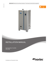
NHRS Models
The NHRS is Nortec’s flagship resistive element electric humidifier. Since it can accept a variety
of supply water types (potable, Reverse Osmosis, De-Ionized), it is very robust and useful in a
wide set of applications. The NHRS is available in capacities ranging from 10 lb/hr (4.5 kg/hr)
to 180 lb/hr (81.6 kg/hr). NHRS humidifiers are packaged in two different cabinets, depending
on their capacity. Figure 3 shows the configuration and relative size of the different cabinets.
Table 3 on page 7 provides specifications for the NHRS product line.
Figure 3: NHRS Models
Double Unit (NHRS 135-180)
NHRS double units have two tanks to provide increased capacity. The construction and
installation of double units is identical to units with a single tank with the following exceptions:
In addition to having two tanks, double units also have two Driver Boards. One Driver
Board controls each tank.
Double units can operate both tanks in series or parallel from a single control signal
Parallel Operation – If configured for parallel operation, only one set of control wiring is
required. The tanks operate in parallel giving the advantage of even wear on both tanks.
Series Operation – One tank’s output range is 0-50% and the other tank’s output range
is 50-100%. An advantage is that a lower turndown ratio can be applied to one tank.
Hybrid Mode – One tank operates using Solid State Relay switching, the other tank
operates using contactor switching. See P/N 2530631.
Double units have one primary power connection, but have individual fill, drain, and
steam outlet connections for each tank.

Introduction | 6
Outdoor Model
The NHRS is available for outdoor use, providing a weatherproof enclosure that allows for
installation on rooftops in relatively extreme climates. Refer to the installation addendum that
is provided with the NHRS Outdoor model to ensure proper installation (P/N 2531550).
Options and Accessories
Nortec provides a complete line of options and accessories for every humidification application.
The following options and accessories are available and may have been delivered with your
NHRS humidifier. Refer to the installation instructions that came with the accessories for
proper installation and operation.
Table 2: Options and Accessories
Component
Function of Component
Drain Water
Cooler, Low
Flow
Reduces drain rate from the humidifier by restricting the boiling tank drain
outlet diameter, as well as providing a lower-flow drain water cooling valve.
Dual Demand
Controller
Consists of a universal math module that compares two demand input signals
and outputs the lowest of the two to the humidifier. This option is useful
where a high limit modulating demand channel is desired (along with a
modulating demand channel humidistat), since the humidifier only allows one
modulating input. See P/N 2558776.
Keep Warm
(Outdoor
standard)
Maintains water temperature in boiling tank at 160ºF (70ºC) for quick
response of the unit to a call for humidity while minimizing health concerns
associated with standing water. See P/N 1504561.
Nortec
Online/LINKS2
Provides monitoring and control, allowing humidifier to communicate with a
Building Management System (BMS). Controller is factory installed and
located internally to the humidifier. At the time of ordering, customer must
specify the desired protocol: BACnet/IP, BACnet/MSTP, Johnson N2, or
LonWorks.
Nortec Online provides an internet-based monitoring and control system for
the humidifier.
Remote Relay
Board
Provides four built-in status relays for remote monitoring capabilities: steam
production, unit fault, maintenance/service, and unit power. Relays can
interface with a Building Management System (BMS). If one of the above
conditions is met, a relay will close which will complete a connection. A signal
will be provided to a wire terminal. See P/N 1508069.
Scale
Management
System
Provides a separate reservoir underneath boiling tank for scale collection.
Minerals removed from the boiling tank water during steam production will
collect in the scale reservoir rather than in the tank. When minor
maintenance is needed, the scale tank is easily removed and emptied.
Solid State
Relays
Allow for rapid response upon call for humidity, adapting instantly to humidity
demand, allowing for tight control of the in-space humidity.

7 | Introduction
Table 3: NHRS Specifications
Phase
Capacity
lb/hr (kg/hr)
Volts
NHRS Part
No.
Amps
Max
Ext
Fuse
kW
Fill
gpm
(l/min)
Net/Full
Weight lb
(kg)
1
10 (4.5)
208
2530540
18.4
25
3.83
3.8
(14.4)
119/190
(54/86)
10 (4.5)
220-240
2530541
15.9
20
3.83
10 (4.5)
440-480
2530542
8.0
15
3.83
10 (4.5)
550-600
2530543
6.4
15
3.83
15 (6.8)
208
2530544
24.5
35
5.10
15 (6.8)
220-240
2530545
21.3
30
5.10
15 (6.8)
440-480
2530546
10.6
15
5.10
15 (6.8)
550-600
2530547
8.5
15
5.10
20 (9.0)
208
2530548
36.8
50
7.65
20 (9.0)
220-240
2530549
31.9
40
7.65
20 (9.0)
440-480
2530550
15.9
20
7.65
20 (9.0)
550-600
2530551
12.8
20
7.65
30 (13.6)
208
2530552
49.0
70
10.20
30 (13.6)
220-240
2530553
42.5
60
10.20
30 (13.6)
440-480
2530554
21.3
30
10.20
30 (13.6)
550-600
2530555
17.0
20
10.20
3
30 (13.6)
208
2530556
31.9
40
11.48
30 (13.6)
220-240
2530557
27.6
35
11.48
30 (13.6)
440-480
2530558
13.8
20
11.48
30 (13.6)
550-600
2530559
11.1
15
11.48
45 (20.4)
208
2530560
42.5
60
15.30
45 (20.4)
220-240
2530561
36.9
50
15.30
45 (20.4)
440-480
2530562
18.4
25
15.30
45 (20.4)
550-600
2530563
14.7
20
15.30
65 (29.4)
208
2530606
63.8
80
22.98
65 (29.4)
220-240
2530609
55.3
70
22.98
65 (29.4)
440-480
2530610
27.6
35
22.95
65 (29.4)
550-600
2530611
22.1
30
22.95
90 (40.8)
440-480
2530612
36.9
50
30.60
90 (40.8)
550-600
2530613
29.5
40
30.60
135 (61.2)
440-480
2530614
55.3
70
45.90
7.6
(28.8)
186/330
(85/150)
135 (61.2)
550-600
2530615
44.2
60
45.90
180 (81.6)
440-480
2530616
73.7
100
61.20
180 (81.6)
550-600
2530617
59.0
80
61.20

Installation | 8
Installation
9 Typical Humidifier
Installation
10 Location
11 Blower Pack Clearance
Requirements
12 Mounting with Keyholes
13 Plumbing
14 Steam Distributor
15 Steam Lines and
Condensate Return
21 Electrical
22 External Controls
22 Control Wiring
22 Duct Humidification
23 Space Humidification
24 On/Off Control Wiring
26 Modulating Control Wiring
28 Transducer Control Wiring
29 Optional Outdoor
Temperature Setback
Sensor
30 Remote Fault Option
Wiring
31 Options and Accessories
32 Keep Warm (Outdoor Standard)
32 Nortec Online/LINKS2
32 Remote Relay Board
32 Scale Management System
32 Solid State Relays

9 | Installation
Typical Humidifier Installation
Figure 4: Typical Humidifier Installation
Mounting
Page 10
Steam
Distribution
Page 14
Controls
Page 21
Electrical
Page 20
Plumbing
Page 13

Installation | 10
Location
Mount on a suitable wall or vertical surface. Do not sit the unit on the floor to allow
clearances required for plumbing and electrical connections.
Clearance dimensions shown are for reference only and are the minimum required for
maintenance of the humidifier. Consult local and national codes before final location
and installation. Nortec does not accept responsibility for installation code violations.
Install only in areas with ambient temperatures between 41 and 104ºF (5 and 40ºC),
and relative humidity between 5 and 95% (non-condensing).
When possible, install the humidifier below the steam distributor. If mounted above the
steam distributor, take care to provide proper steam line routing and proper condensate
traps.
DO NOT locate the humidifier any further than absolutely necessary from the steam
distributor location as net output will be reduced as a result of heat loss through the
steam line.
When possible, mount the humidifier at a height convenient for servicing.
Figure 5: Mounting Location / Clearance
Note: Do not mount on hot surfaces, where freezing can occur, vibrating surfaces, or
floor.

11 | Installation
Blower Pack Clearance Requirements
For more information regarding the clearance requirements of the Remote Mounted Blower
Pack (P/N 2572615), refer to installation manual (document number 2572641).
Table 4: Clearances for Blower Packs on Low Speed*
Humidifier
Capacity
lb/hr (kg/hr)
Min. Frontal
Clearance
Inches (cm)
Min. Overhead
Clearance
Inches (cm)
Min. Left Side
Clearance
Inches (cm)
Min. Right Side
Clearance
Inches (cm)
Up to 30 (13.6)
132 (336)
12 (31)
12 (31)
12 (31)
30-100
(13.6-45.4)
Not
recommended
Not
recommended
Not
recommended
Not
recommended
Table 5: Clearances for Blower Packs on High Speed*
Humidifier
Capacity
lb/hr (kg/hr)
Min. Frontal
Clearance
Inches (cm)
Min. Overhead
Clearance
Inches (cm)
Min. Left Side
Clearance
Inches (cm)
Min. Right Side
Clearance
Inches (cm)
Up to 30 (13.6)
132 (336)
12 (31)
12 (31)
12 (31)
30-100
(13.6-45.4)
Not
recommended
Not
recommended
Not
recommended
Not
recommended
*NOTES:
Nominal Conditions: 72ºF (22.2ºC), 43% RH.
Low speed not recommended for 50-100 lb/hr humidifiers.
Blower Pack should not be installed near cold surfaces or where dew point may be reached.
Higher humidity or lower room temperature may result in longer absorption distances.

Installation | 12
Mounting with Keyholes
1. The NHRS Series humidifier is wall mounted using keyholes located on the back of the
unit cabinetry.
2. Use #12 x 3” (7.5 cm) screws mounted into 2x4” studs or better. Two screws are
required for units with one tank (NHRS 10 to NHRS 90 lb/hr). Three screws are required
for units with two tanks (NHRS 135 and 180 lb/hr).
3. Keyholes are spaced 16” (40.6 cm) apart center to center as per UL certification
standard stud spacing dictates. Insert screws into the studs until there is ¼” (0.6 cm) of
screw exposed. Ensure the screws are level to each other.
4. Raise the unit and place the screws through the keyholes. Make sure the unit is level
before tightening the screws to secure the unit in place.
5. Place L-shaped brackets on top of the unit, ensuring the holes are in-line with the studs.
Using the appropriate sized wood screw, fasten the L-brackets to the studs, securing the
unit from any upwards motion. See Figure 6.
Figure 6: Mounting with Keyholes; A = B = 16” (40.6 cm)
Note: Use screws longer than 3” (7.5 cm) if drywall or other spacer is present.

13 | Installation
Note: • Drain water is very hot, do not drain to public sink.
• Use material suitable for 212ºF (100ºC) for drain and condensate lines.
Plumbing
All water supply and drain line connections should be installed in accordance with local
plumbing codes.
Supply water should have pressure between 30 and 80 psi
g
and have a hardness
between 0 and 12 gr/gal. Various types of supply water may be used: soft water, de-
ionized, reverse osmosis, or potable.
Install water shut-off valve and union before humidifier to facilitate servicing.
The drain line should not end in a sink used frequently by personnel, or where plumbing
codes prohibit. Route to a floor drain or equivalent for safety reasons.
Ensure drain line is adequately sized to provide free and easy draining. Ensure air gap is
installed as shown. A restricted drain can cause the boiling tank to become heavily
concentrated with minerals and may result in poor operation or water backing up at the
air gap.
Figure 7: Water Supply and Drain Connection

Installation | 14
Steam Distributor
Steam generated by the NHRS may be distributed directly into a conditioned
environment with a Remote Blower Pack (P/N 2572615), or into an air handling system
using either Nortec steam distributors or Nortec’s SAM-e steam distribution manifold.
The steam distributor should be installed as close as possible to the humidifier. Short
steam distribution lines minimize condensate losses and the possibility of generating
back pressure in the steam distribution line.
Figure 8 provides common guidelines for locating a steam distributor in a duct.
Figure 8: Distributor Location in Duct
Note:
• Install the NHRS as close as possible to whatever steam distributor is used.
• Refer to distributor, SAM-e, or Remote Blower Pack installation manuals for detailed
installation instructions (2556592, 1507619, and 2572641, respectively)

15 | Installation
Steam Lines and Condensate Return
The following instructions must be followed for installation of steam lines for ASD, BSD, CSD,
SAM-e, and Remote Blower Packs. Failure to used material in Table 6 and Table 7 on page 16,
or failure to follow any other steam line installation instructions, will result in improper operation
and could void warranty.
Table 6: Recommended Maximum Length of Steam Line
NHRS
Unit
Size
Steam
Output
(lbs/hr)
Distance
ft (m)
Possible
Loss
ft (m)
Steam
Line
Size
010
10
15 (4.5)
2 (0.6)
1.5”
015
15
17.5 (5)
2.25 (0.7)
020
20
20 (6)
2.5 (0.8)
030
30
25 (7.5)
3 (0.9)
045
45
35 (10.5)
4 to 5 (1.2 to 1.5)
065
65
45 (13.5)
5 to 10
(1.5 to 3.0)
090
90
50 (15)
135
135
50/tank (15)
2 x 1.5”
180
180
50/tank (15)
NOTES:
1) This chart gives the maximum length of recommended steam line by unit size.
2) The use of steam line other than copper, stainless steel, or Nortec steam hose will void the
warranty and may cause adverse effects regarding the operation of the humidifier.
3) Nortec steam line shall only be used for steam line runs of 10 ft (3m) or less.
4) Long steam runs affect accuracy of humidifier and its ability to quickly respond to changes in
demand. When tight control is required, ensure steam line run is as short as possible.
5) NHRS 135 and 180 have two tanks.
Danger:
The NHRS is an atmospheric humidifier that will only operate properly when its steam
distribution system is installed so that it provides no significant backpressure.
Installing the NHRS in such a way that backpressure can develop during operation
could result in serious injury or damage to property.

Installation | 16
Table 7: Recommended Materials and Sizes for Steam Runs.
Supply
Water
Type
Tank Size
(lbs/hr)
Steam Run
ft (m)
Steam Line
Material
Steam Line
Description
Potable
0-30
0-10 (0-3)
Copper Tube
1.5” MED-L Tubing
(1.625” OD)
0-30
10-30 (3+)
Copper Tube
2.0” MED-L Tubing
(2.125” OD)
RO or
DI
0-30
0-10 (0-3)
Stainless Steel Tube
1.75” Tube x
0.065” thick
0-30
10-30 (3+)
Stainless Steel Tube
2.0” Tube x
0.065” thick
Potable
45-90
0-20 (0-6)
Copper Tube
1.5” MED-L Tubing
(1.625” OD)
45-90
20+ (6+)
Copper Tube
2.0” MED-L Tubing
(2.125” OD)
RO or
DI
45-90
0-20 (0-6)
Stainless Steel Tube
1.75” Tube x
0.065” thick
45-90
20+ (6+)
Stainless Steel Tube
2.0” Tube x
0.065” thick

17 | Installation
S
t
e
a
m
D
i
r
e
c
t
i
o
n
S
t
e
a
m
D
i
r
e
c
t
i
o
n
S
t
e
a
m
D
i
r
e
c
t
i
o
n
2 in.
(5 cm)
1 ft (30 cm)
1ft (30 cm)
0.5 in.
(12 mm)
10 Degrees
2 Degrees
Use Appropriate Slope Insulate Pipe
1 in. (2.5 cm) pipe
insulation
Minimal Slope (up)
Minimal Slope (down)
Figure 9: Steam Line Slope and Installation
Trap condensate
• Trap at all low points and recommended intervals using full size ‘T’ for traps.
• Condensate should not be routed to a sink used frequently by personnel. Route to a floor
drain or equivalent. Condensate normally cools in traps but is still hot. A SAM-e or larger
steam line generates more condensate and water may not cool in the trap. A drain water
cooler option may be installed if required by code.
• Route condensate to floor drain or equivalent in multi-unit to single SAM-e installation.
Figure 10: Condensate Traps
/