Page is loading ...

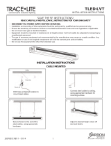
NH
Series
Installation and
Operation Manual
Includes installation, operation
maintenance and troubleshooting
information for your NHRS Resistive
Element Steam Humidifier
2530618-
* | 08 SEP 2010
Important: Read and save these instructions. This guide to be left with equipment.

Thank you for choosing NORTEC.
Proprietary Notice
This document and the information disclosed herein are proprietary data of WALTER MEIER LTD. Neither this
document nor the information contained herein shall be reproduced used, or disclosed to others without the
written authorization of WALTER MEIER LTD., except to the extent required for installation or maintenance of
recipient’s equipment. All references to the NORTEC name should be taken as referring to WALTER MEIER LTD.
Liability Notice
NORTEC does not accept any liability for installations of humidity equipment installed by unqualified personnel
or the use of parts/components/equipment that are not authorized or approved by NORTEC.
Copyright Notice
Copyright 2009, WALTER MEIER LTD. All rights reserved.
INSTALLATION DATE (MM/DD/YYYY)
MODEL #
SERIAL #
CYLINDER #

TABLE OF CONTENTS
10-00 INTRODUCTION
1. PRE-INSTALLATION . . . . . . . . . . . . . . . . . . . . . . . . . . . . . . . . . . . . . . . . . . . . . . . . . . . . . . . . . . .3
2. PACKAGING. . . . . . . . . . . . . . . . . . . . . . . . . . . . . . . . . . . . . . . . . . . . . . . . . . . . . . . . . . . . . . . . . .3
3. PRE-INSTALLATION EQUIPMENT VERIFICATION . . . . . . . . . . . . . . . . . . . . . . . . . . . . . . . . . . .5
10-10 INSTALLATION PROCEDURES
1. HUMIDIFIER INSTALLATION . . . . . . . . . . . . . . . . . . . . . . . . . . . . . . . . . . . . . . . . . . . . . . . . . . 10
2. STEAM DISTRIBUTOR INSTALLATION FOR THE ASD, BSD, CSD . . . . . . . . . . . . . . . . . . . . .27
3. SAM-E SHORT ABSORPTION MANIFOLD . . . . . . . . . . . . . . . . . . . . . . . . . . . . . . . . . . . . . . . . .33
4. BLOWER PACKS (BOBP, RMBP. . . . . . . . . . . . . . . . . . . . . . . . . . . . . . . . . . . . . . . . . . . . . . . . .41
10-20 OPERATION
1. OPERATION . . . . . . . . . . . . . . . . . . . . . . . . . . . . . . . . . . . . . . . . . . . . . . . . . . . . . . . . . . . . . . . 46
2. NHRS OPERATION . . . . . . . . . . . . . . . . . . . . . . . . . . . . . . . . . . . . . . . . . . . . . . . . . . . . . . . . . . .47
10-30 MAINTENANCE PROCEDURES
1. NHRS MAINTENANCE. . . . . . . . . . . . . . . . . . . . . . . . . . . . . . . . . . . . . . . . . . . . . . . . . . . . . . . . .62
10-40 TROUBLESHOOTING
1. TROUBLESHOOTING . . . . . . . . . . . . . . . . . . . . . . . . . . . . . . . . . . . . . . . . . . . . . . . . . . . . . . . . .68
2. START-UP CHECK LISTS . . . . . . . . . . . . . . . . . . . . . . . . . . . . . . . . . . . . . . . . . . . . . . . . . . . . . .72
3. MAINTENANCE CHECK LISTS . . . . . . . . . . . . . . . . . . . . . . . . . . . . . . . . . . . . . . . . . . . . . . . . . .75
10-50 TECHNICAL
1. EXPLODED VIEWS - PLUMBING . . . . . . . . . . . . . . . . . . . . . . . . . . . . . . . . . . . . . . . . . . . . . . . .78
2. EXPLODED VIEWS ELECTRICAL. . . . . . . . . . . . . . . . . . . . . . . . . . . . . . . . . . . . . . . . . . . . . . . .80
WARRANTY


Introduction
CAUTION: Servicing
Disconnect main power before any servicing.
The plumbing and electrical compartments contain high voltage components and
wiring. Access should be limited to authorized personnel only.
During and following operation of the humidifier, the steam and components in
contact with the steam such as the cylinder, blower pack, steam lines, steam
distributors, and condensate lines can become hot and can burn if touched.
Walter Meier does not accept any liability for installations of humidity equipment
installed by unqualified personnel or the use of parts/components/equipment
that are not authorized or approved by Walter Meier.
CAUTION: Electrical
All electrical work should be done according to local electrical code.
Electrical connection to be performed by a licensed electrician.
CAUTION: Plumbing
Plumbing to be performed by a licensed plumber.
Drain water from humidifier can be very hot. Do not drain to public sink.
All plumbing work should be done according to local plumbing code.
CAUTION: Installation
Do not mount on hot surfaces
Do not mount in area where freezing can occur
Do not mount on vibrating surface
Do not mount on floor
The NHTC produces steam at atmospheric pressure no devices which could block
steam output should be connected to the steam outlet.
Steam lines must be installed so that no restriction can produce backpressure in
the humidifier.
Regardless of selecting On/Off or modulating control method, NORTEC humidifiers
must have a closed circuit across its On/Off security loop control terminal to
operate. NORTEC highly recommends the use of a high limit humidistat and an air
proving switch in series for this function.

Page 1
10-00
INTRODUCTION

Page 2
Figure 1. NHRS

Page 3
1. PRE-INSTALLATION
A. RECEIVING & UNPACKING EQUIPMENT
(1) Check packing slip to ensure ALL material has been delivered. All material
shortages are to be reported to NORTEC within 48 hours from the receipt of
good. NORTEC assumes no responsibility for any material shortages beyond this
period.
(2) Inspect shipping boxes for damage and note damages on shipping waybill
accordingly. After unpacking, inspect equipment for damage. If damage is found
notify shipper promptly. All NORTEC products are shipped on a FOB factory
basis. Any and all damage, breakage or loss claims are to be made directly to
the shipping company.
2. PACKAGING
A. GENERAL
(1) The equipment packaging is standardized in that each box will contain the same
base content. The following paragraphs identify the content of each box.
B. HUMIDIFIER AND CONTROL BOX
(1) The typical equipment found in the humidifier and control box are shown in
Figure 2. The contents are listed on the box. If controls and any other small
accessories are placed in the box they will be listed on the box.
C. DISTRIBUTOR BOX
(1) Depending on the equipment ordered the following distributor box configurations
may be received.
(2) For equipment received if an ASD, BSD, CSD distributors are ordered refer to
Figure 3.
(3) For equipment received if a SAM-e is ordered refer to Figure 4.
(4) For equipment received if a RMBP is ordered refer to Figure 5.

Page 4
H096
BOX WITH
ABBREVIATED
INSTRUCTIONS
AND BOX
CONTENT
STICKERS
CONTROLS
(IF ORDERED
ONLY)
BAG WITH
MANUAL,
CLAMPS,
HOSE SECTION
HUMIDIFIER
STEAM HOSE
SECTION (NOT
SUPPLIED IF BUILT
ON BLOWER PACK
ORDERED)
Figure 2. Humidifier Box
Figure 3. Distributor Box
Figure 4. SAM-e Distributor Box
Figure 5. Remote Mounted Blower Pack Box

Page 5
3. PRE-INSTALLATION EQUIPMENT VERIFICATION
A. GENERAL
(1) Ensure the available voltage and phase correspond with humidifier voltage and
phase as indicated on the humidifier’s specification label.
(2) Ensure that the external fuse disconnect is sufficient size to handle the rated
amperage as indicated on the humidifier’s specifications label. Refer to local building
codes.
(3) Report any discrepancy immediately to the site engineer.
(4) Location and mounting is described in Chapter 10-10.
(5) For typical installation see Figures 6 & 7.

Page 6
Figure 6. Typical NHRS Installation (Sheet 1 of 2)

Page 7
Figure 7. Typical NHRS Installation (Sheet 2 of 2)

Page 8
THIS PAGE INTENTIONALLY LEFT BLANK

Page 9
10-10
INSTALLATION
PROCEDURES

Page 10
1. HUMIDIFIER INSTALLATION
A. LOCATION
(1) The NORTEC NHRS series humidifier is designed to mount on a suitable wall or
vertical surface. Do not sit the unit on the floor due to clearances required for
plumbing and electrical connections. The clearance dimensions shown in this
manual are for reference only and are the minimum required for maintenance on
the humidifier. Local and national codes should be consulted before final location
and installation of the humidifier. NORTEC cannot accept responsibility for
installation code violations.
(2) The location of the humidifier should be below the steam distributor. DO NOT
locate the humidifier any further then absolutely necessary from the steam
distributor location as net output will be reduced as a result of heat loss through
the steam line.
(3) When possible, mount the NHRS humidifier at a height convenient for servicing.
B. MOUNTING
(1) The NHRS series humidifier is wall mounted using keyholes located on the back
of the unit‟s cabinetry. The keyholes are spaced 16 inches apart center to center
as per UL certification standard stud spacing dictates.
(2) Use #12 x 3 in. screws. 2 screws are needed for a single unit (NHRS 010 to 090
lbs/hour). 3 screws are needed for a double unit (NHRS 135 to 180 lbs/hour).
Insert the screw 16 in. apart. Be sure the screws are level to each other. Proceed
to insert the screws into the studs until there is 1/4 in. of screw exposed. Ensure
the screws are properly anchored to the wall.
(3) Raise the unit. Align the keyholes on the back of the unit with the screws. Place
the screws through the keyholes. Make sure the unit is level then tighten the
screws to secure the unit in place.
(4) Once the unit is securely fixed to the wall, install the “L” shaped brackets into the
same studs the unit is attached to. Place the brackets on top of the unit, inline
with the studs. Using the appropriate sized wood screw fasten the “L” brackets
to the studs securing the unit from any upward motion.

Page 11
C. WATER SUPPLY LINE (Potable Water Supply)
(1) All water supply and drain line connections should be installed in accordance
with local building codes.
(2) It is always recommended to install a manual shut off valve on the fill water
supply line dedicated to the humidifier to facilitate servicing. Use 1/2 in. outside
diameter copper piping to the humidifier. See Figure 1 for further detail.
D. WATER SUPPLY LINE (De-ionized Water Supply)
(1) All water supply and drain line connections should be installed in accordance
with local building codes.
(2) It is always recommended to install a manual shut off valve on the fill water
supply line dedicated to the humidifier to facilitate servicing. Use 1/2 in. plastic or
stainless steel tubing to connect to the humidifier. See Figure 1 for further detail.

Page 12
Figure 1. Plumbing Connections

Page 13
E. WATER DRAIN LINE
(1) All water supply and drain line connections should be installed in accordance
with local building codes.
(2) The NHRS comes equipped with a 1-1/2 in. drain outlet on the under side of the
drain canal. Attach the factory supplied 1-1/2 in. hose to the drain outlet.
(3) A 1 in. air gap is needed in the drain line to prevent any backflow or siphoning
from occurring. It is recommended to place this air gap as close to the unit as
possible to limit any chance of siphoning. A copper funnel should be used
reducing the drain line to a minimum of 2 in. O.D. pipe. If DI or RO water is used,
stainless steel is recommended for the drain line and funnel. Purified water will
deteriorate copper over time and use. See Figure 1 for further detail.
(4) The drain line should not end in a sink used frequently by personnel, or where
plumbing codes prohibit it, route to a floor drain or equivalent for safety reasons.

Page 14
F. SCALE MANAGEMENT SYSTEM INSTALLATION
Figure 2. Installation of the Scale Tank Bracket
(1) Line up holes in bracket with holes in drain pan. Fasten the bracket to the
drain pan using the four #10-32 nylon lock nuts.
(2) Fasten the front of the bracket with the two #10-24 self tapping screws
provided.
(3) The two locking screws for the bracket should already be installed.

Page 15
Figure 3. Installation of the Scale Tank
(1) Unlock support bracket by removing locking screws.
(2) Open both mechanisms by rotating counter clockwise until opening is
visible.
(3) Place scale tank on support bracket.
(4) Rotate bracket to close mechanism and raise scale tank. Note ensure
scale tank lines up with opening at the bottom of the drain pan when
raising.
(5) Lock mechanism by re-inserting the two locking screws.
/