Page is loading ...

AEM Performance Electronics
2205 126
th
Street Unit A, Hawthorne, CA. 90250
Phone: (310) 484-2322 Fax: (310) 484-0152
http://www.aempower.com
Instruction Part Number: 10-5131 Rev 04
2009 AEM Performance Electronics
Part Number 30-5131
Analog EGT Gauge
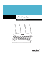
Figure 1. Wiring Schematic
AEM EGT Gauge Parts
1 x 35-5131(B/W) EGT Gauge Assembly
1 x 30-2065 EGT Sensor Thermocouple w/Mount
1 x 35-4302 Install Kit (6 Butt Connectors)
1 x 10-5131 Installation Instructions
1 x 35-3411 8-Pin Power Harness
1 x 35-3414 2-Pin Sensor Harness
1 x 35-8529S Silver Bezel
1 x 6” Heat Shrink
2 x 4-40 Hex Nut
2 x 4-40 Screw

Page 2
INSTALLATION
1. Disconnect the negative battery cable.
2. Secure the gauge in a 2 1/16
th
” (52MM) mounting hole with the supplied bracket.
3. Plug the 8-wire power harness into the mating connector on the back of the
gauge and connect the wires as shown in Figure 1. Note: the locating tabs on
the side of the connector should be nearest the center of the gauge.
4. Connect the sensor cable to the gauge. The locating tabs should be closest to
the center of the gauge.
5. Mount the thermocouple as shown in figure 2.
6. Slide the heat shrink tube over the sensor cable and connect the thermocouple to
the cable as shown below in figure 3.
RED - Connect BOTH RED wires to a constant 12 volt power source utilizing a 5A fuse.
BLACK – Connect BOTH BLACK wires to a clean ground.
PINK - Connect to a switched 12 volt power source utilizing a 5A fuse.
GREY - Connect to instrument lighting circuit supply voltage.
*WHITE - Connect to Analog + Input.
*BROWN - Connect to Analog – input. (Must be connected if Analog + is used)
*optional – only needed if using the available differential analog output
Wiring notes:
RED - When wired as shown above, the gauge will park the needle upon
powering down. Alternatively, both RED wires can be connected to a switched, fused
12 volt power source. With both RED wires and the PINK wire connected to switched
power, the needle will remain at its current position upon powering down. For both
power connection methods, the needle will rotate to the parked position before rotating
to the value of the current operating condition upon powering up.
GREY – The GREY wire is used to control the lighting intensity of the gauge.
Maximum lighting intensity is achieved when the GREY wire is connected to 12 volts.
Minimum lighting intensity is achieved when the GREY wire is not connected. The
instrumentation illumination on many vehicles is controlled by varying the supply voltage
to the instrument panel lights. When the GREY wire is connected to the instrument
panel supply voltage, the intensity of the gauge is controlled by the dimmer switch on
the dash.
WHITE – The WHITE wire should be connected to the Analog + input on the
EMS or the analog + input on a similar device.
BROWN – The BROWN wire should be connected to the Analog – input. If the
EMS or similar device does not have a – input, the BROWN wire should be connected
to a sensor ground. If no sensor ground is available, the BROWN wire should be
connected to a power ground. Note: The BROWN wire must be connected in order
to get correct readings from the analog output.

Page 3
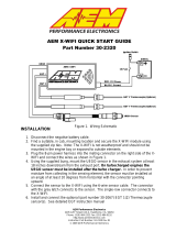
Thermocouple Mounting
The thermocouple included in the kit comes with a stainless steel compression style
mounting adapter. The mounting adapter consists of three pieces: compression nut,
ferrule sleeve, threaded body. The threaded body has 1/8” NPT male threads. To
install the sensor, the threaded body can either be threaded into a hole with mating 1/8”
NPT threads, or welded to the pipe/manifold. Remove the compression nut, ferrule
sleeve, and thermocouple from the threaded body. For a welded installation, drill a
13/32” hole and weld the threaded body, being careful not to cause any distortion. .
For a threaded installation, either thread the body into an existing hole with 1/8” NPT
threads or drill a hole using an “R” size drill bit and cut the threads using a 1/8” NPT tap.
With the compression nut and ferrule sleeve on the thermocouple, insert the
thermocouple into the threaded body so the tip of the thermocouple is near the center of
the pipe/manifold and tighten the compression nut to the threaded body.
Connecting the Thermocouple
Slide the supplied heat shrink onto the sensor cable. Connect the RED wire from the
thermocouple to the RED wire on the harness and the YELLOW wire from the
thermocouple to the YELLOW wire on the harness using the supplied 4-40 screws and
hex nuts. Make sure the connections are not touching. Center the heat shrink over the
connections and apply mild heat to the heat shrink until it shrinks over the connections.
FERRULE SLEEVE
COMPRESSION NUT
THREADED BODY
PIPE/MANIFOLD
WITH 1/8” NPT
THREADS OR
13/32” HOLE
TIP OF THERMOCOUPLE
NEAR CENTER OF
PIPE/MANIFOLD
HEAT SHRINK
Figure 3. Thermocouple to Cable Connection
Figure 2. Thermocouple Mounting

Page 4
Changing the Bezel
The AEM Analog EGT Gauge comes with the black bezel installed. However, a silver
bezel is also included in the gauge kit. To change the bezel, orient the gauge so you
are looking at the faceplate. Rotate the bezel counter-clockwise to unscrew it from the
gauge cup. The bezel, lens, and rubber spacer are all removable. Reassemble the
gauge as shown below in Figure 4. Do not over tighten the bezel when
reassembling the gauge.
Backlighting
The AEM Analog EGT Gauge has 7 different backlight colors available to the end user,
which closely match some of the more common factory dash panels: white, blue, green,
red, orange, light blue, and aqua. To change the backlight color, rotate the backlighting
switch using a small precision style screwdriver. The backlight switch is accessed
through the small hole in the back of the gauge. See Figure 5.
Figure 4. Changing Bezels
Figure 5. Backlighting Adjustment
ACCESS
PORT
BEZEL
LENS
RUBBER
SPACER

Page 5
Status Lights
The AEM Analog EGT Gauge has one status light, see Figure 6. The status light will
flash whenever the sensor is disconnected.
Analog Output
The analog output from the AEM Analog EGT gauge is a linear dc voltage signal that
varies from 0.5 Vdc at 0 Degrees Fahrenheit (-18 Degrees Celsius) to 4.5Vdc at
1800 Degrees Fahrenheit (982 Degrees Celsius) over the operating range of the
gauge. The signal is used for sending information to a data logger or an engine
management system like the AEM EMS or F/IC. The transfer functions for the analog
output are listed below in Degrees Fahrenheit and Degrees Celsius.
Temperature (Degrees Fahrenheit) = 450 * Voltage - 225
For example, if the output is 2.5 Vdc, the temperature is 900 Degrees Fahrenheit.
450 * 2.5 – 225 = 900 Degrees Fahrenheit
Temperature (Degrees Celsius) = 250 * Voltage – 143
For example, if the output is 2.5 Vdc, the temperature is 482 Degrees Celsius.
250 * 2.5 – 143 = 482 Degrees Celsius
A list of output voltages and corresponding temperatures is shown below in Table 1.
Figure 6. Illuminated Status Light
Error
Status
Light

Page 6
VOLTAGE
°F
°C
0.50
0
-18
0.75
113
45
1.00
225
107
1.25
338
170
1.50
450
232
1.75
563
295
2.00
675
357
2.25
788
420
2.50
900
482
2.75
1013
545
3.00
1125
607
3.25
1238
670
3.50
1350
732
3.75
1463
795
4.00
1575
857
4.25
1688
920
4.50
1800
982
Connector Pinouts
The pinouts for the 3-pin sensor harness and 8 pin power harness are provided
below in Figure 6.
Specifications
Gauge
Supply Current
<0.100 A
Differential Analog Outputs
1
Measuring Range
0 – 1800 Degrees Fahrenheit,
-18-982 Degrees Celsius
Sensor Accuracy
0.75% FS
Operating Voltage (nominal)
8.5-15 volts dc
Harness & Connector Temp Limit:
105C
Figure 6. Harness Pinouts
Table 1. Analog Calibrations

Page 7
NOTES:
If further tuning help is needed be sure to visit the video gallery or performance electronics
forum at www.aempower.com for comprehensive instructional videos and information.
Replacement EGT Gauge Components
30-2065 K-Type Thermocouple with Bung
35-3411 8-Pin Power Harness
35-3414 3-Pin Sensor Harness
12 MONTH LIMITED WARRANTY
Advanced Engine Management Inc. warrants to the consumer that all AEM High Performance products will be free from defects in
material and workmanship for a period of twelve (12) months from date of the original purchase. Products that fail within this 12-
month warranty period will be repaired or replaced at AEM’s option, when determined by AEM that the product failed due to defects
in material or workmanship. This warranty is limited to the repair or replacement of the AEM part. In no event shall this warranty
exceed the original purchase price of the AEM part nor shall AEM be responsible for special, incidental or consequential damages
or cost incurred due to the failure of this product. Warranty claims to AEM must be transportation prepaid and accompanied with
dated proof of purchase. This warranty applies only to the original purchaser of product and is non-transferable. All implied
warranties shall be limited in duration to the said 12 month warranty period. Improper use or installation, accident, abuse,
unauthorized repairs or alterations voids this warranty. AEM disclaims any liability for consequential damages due to breach of any
written or implied warranty on all products manufactured by AEM. Warranty returns will only be accepted by AEM when
accompanied by a valid Return Goods Authorization (RGA) number. Product must be received by AEM within 30 days of the date
the RGA is issued.
Please note that before AEM can issue an RGA for any product, it is first necessary for the installer or end user to contact the AEM
Performance Electronics tech line at 1-800-423-0046 to discuss the problem. Most issues can be resolved over the phone. Under
no circumstances should a system be returned or a RGA requested before the above process transpires.
Need additional help? Contact the AEM Performance Electronics tech department at
1-800-423-0046 or [email protected], or visit the AEM Performance Electronics
forum at http://forum.aempower.com/forum/
/