Page is loading ...

RI.15KI
CENTRALINA A MICROPROCESSORE PER
CONTROL UNIT WITH MICROCONTROLLER FOR
MIKROCONTROLLER-STEUERUNG FÜR
CENTRALE A MICROCONTRÔLEUR POUR
CENTRALITA A MICROPROCESADOR POR
L8542624
Rev. 04/03/02
Libro istruzioni
Operating instructions
Betriebsanleitung
Livret d’instructions
Libro de instrucciones
UNIONE NAZIONALE COSTRUTTORI
AUTOMATISMI PER CANCELLI, PORTE,
SERRANDE ED AFFINI
A
Z
I
E
N
D
A
C
E
R
T
I
F
I
C
A
T
A
UNI
EN ISO
9001

2
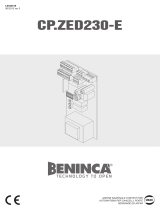
Dichiarazione CE di conformità Déclaration CE de conformité
EC declaration of confirmity Declaracion CE de conformidad
EG-Konformitatserklarung
Con la presente dichiariamo che il nostro prodotto
We hereby declare that our product
Hiermit erklaren wir, dass unser Produkt
Nous déclarons par la présente que notre produit
Por la presente declaramos que nuestro producto
RI.15KI
è conforme alle seguenti disposizioni pertinenti:
complies with the following relevant provisions:
folgenden einschlagigen Bestimmungen entspricht:
correspond aux dispositions pertinentes suivantes:
satisface las disposiciones pertinentes siguientes:
Direttiva sulla compatibilità elettromagnetica (89/336/
CCE, 93/68/CEE)
EMC guidelines (89/336/EEC, 93/68/EEC)
EMV-Richtlinie (89/336/EWG, 93/68/EWG)
Directive EMV (89/336/CCE, 93/68/CEE) (Compatibilité
électromagnétique)
Reglamento de compatibilidad electromagnética (89/336/
MCE, 93/68/MCE)
Norme armonizzate applicate in particolare:
Applied harmonized standards, in particular:
Angewendete harmonisierte Normen, insbesondere:
Normes harmonisée utilisées, notamment:
Normas armonizadas utilzadas particularmente:
EN 55022, EN 61000-3-2, EN 61000-3-3, EN 50082-1
Norme e specifiche tecniche nazionali applicate in
particolare:
Applied national technical standards and specifications, in
particular:
Angewendete nationale Normen und technische
Spezifikationen, insbesondere:
Normes et specifications techniques nationales qui ont été
utilisées, notamment:
Normas y especificaciones técnicas nacionales que se
utilizaron particularmente:
UNI 8612
Data/Firma
Direttiva sulla bassa tensione (73/23/CEE, 93/68/CEE)
Low voltage guidelines (73/23/EEC, 93/68/EEC)
Tiefe Spannung Richtlinie (73/23/EWG, 93/68/EWG)
Directive bas voltage (73/23/CEE, 93/68/CEE)
Reglamento de bajo Voltaje (73/23/MCE, 93/68/MCE)
Norme armonizzate applicate in particolare:
Applied harmonized standards, in particular:
Angewendete harmonisierte Normen, insbesondere:
Normes harmonisée utilisées, notamment:
Normas armonizadas utilzadas particularmente:
EN 60204-1, EN 60335-1
Data/Firma
Automatismi Benincà Srl
Via Capitello, 45
36066 Sandrigo (VI)
ITALIA

3
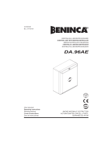
INPUT
LAMP.
230VAC
Chiude
Apre
P.P.
Stop
FTC
FCA
FCC
+V
ASC
8k2
8k2
ASA
N
Chiude Apre COM.
F
230VAC 50Hz
M
Sensore giri
SCA
24VAC
OUT
ANT
Z8
C4
R29
D18
R8
C18
C19
R32
R40
U6
R4
Z9
C21
C15
D26
D25
D9
D8
D7
D6
D5
D4
D3
R57
C20
C16
U3
L2
R61
K4
J3
RTX
D33
Z1
Z2
Z3
Z4
Z5
Z6
Z7
U1
U7
D31
D30
C1
D23
D22
R39
R49
R48
R56
R60
R33
R30
R35
D24
R54
C22
R28
R47
R50
R53
D27
R67
R52
R51
R63
1
33
32
31
30
29
28
FUSE
IN.
230V
C
24
R1
R2
R3
L3
AP.
CH.
P.P.
STOP
FTC
FCA
FCC
ASC
ASA
J1
R27
C2
R59
C3
R58
D32
R31
R12 C13
R13
C12
R14
C11
R15
C10
R17
C9
R18
C8
R16
C7
R19
R26
R11
R25
R10
R24
R9
R23
R7
R22
R6
R21
R20
D2
R36
D10
D11
D12
D13
D14
D15
D16
J2
VDR3
SW1
C6
C5
0
F2 2A
FUSE
FUSE
F1 6.3A
F3 2A
F1
D1
VDR1
C14
C17
+
F2 2A
R46 R44
Q9
D17
D19 D21
D20
R45
R43
R5
K2 K1 K3
D34Power
2 3 4 5 6 7 8 9 10 11 12 13 14 15 16 17 18 19 20 21 22 23
24
SW2
Select
PGM
Q4
RX
2 CH.
25
26
27

8
RI15KI Control unit with microcontroller
The control unit with microprocessor RI.15KI can be used to control motors featuring a power not ex-
ceeding 750W.
Installation instructions.
a) Wire connections and operating logic should comply with regulations in force.
b) It is recommended to keep the power cables (motor, power supply) detached from the control ones
(push-buttons, photocells, radio). To avert any interference, it is advised to use two distinct sheaths.
c) Before powering the unit, rapidly check all connections.
d) Check the correct setting of the Dip-Switches.
e) When the unit is powered, the LED “POWER” must light on. In the negative, check the good condition
of fuses and the presence of 230Vac, 50Hz between terminals 1 and 2 (INPUT 230VAC - follow phase/
neutral).
f) All normally closed inputs, which are not in use, should be short-circuited with the relevant Dip-
Switch located near the connection terminal of the inputs.
g) If the rotation direction of the motor is inverted, it is sufficient to invert the wires “APRE” - “CHIUDE”
(OPEN - CLOSE) of the motor as well as the limit switches wires “FCA” - “FCC”.
Input/Output functions
(1,2) Input, 230VAC= Power supply of the control unit 230Vac, 50Hz (Phase: terminal 2, Neutral: ter-
minal 1).
(3,4,5) Output, Motor= Respectively, Close (3), Open (4) and Common (5).
(6,7) LAMP= To the flashing light at 230Vac
(8) CHIUDE= Normally Open (N.O.) contact
(9) APRE= N.O. contact (it can be switched to “Pedestrian” input)
(10) P.P.= Input, STEP-BY-STEP. Connected in parallel to the remote control. N.O. contact.
(11) STOP= Normally closed (N.C.) contact
(12) FTC= To be connected to the output terminal of the photocell. N.C. contact
(13) FCA= Input, opening limit switch. N.C. contact
(14) FCC= Input, closing limit switch. N.C. contact
(15,16) +V= Output, common for all inputs
(17) ASC= Input, safety edge. Its activation causes the movement reversion for 1 second if the mo-
tor is in the closing phase*
(18) Input, common to the safety edges = Input, common of safety edges. The safety edges MUST
NOT BE CONNECTED TO THE COMMON OF THE PUSH-BUTTONS
(19) ASA= Input, safety edge. Its activation causes the movement reversion for 1 second if the mo-
tor is in the opening phase*
(20,21) SCA= “Open gate LED” contact, 24Vac bulb
(22,23) OUT 24VAC= Output, auxiliary power supply, 24Vac (1A max.)
(24,25) Output, 2nd channel= N.O. contact, controlled by the second channel of the remote control
(26,27) Input, antenna= Antenna connection for the receiving card of the remote control.
Display= terminal 25
(28,29) Input, 24VAC= Connection to the secondary of the transformer, 24V
(30,31) Capacitor= Connection to the capacitor
(32,33) Output, 230VAC= Connection to the primary of the transformer, 24V
RTX= Connector to the receiving card of the remote control.
* The inputs of the safety edges are at calibrated resistance. If a resistive safety edge is used, the
relevant jumpers (J2 for ASC and J1 for ASA) should be closed. Conversely, if a mechanical edge is
used the jumpers should be left open. In the event the safety edges are not mounted, leave the corre-
sponding jumper open and move the short-circuit Dip-Switch to ON (No. 1 for ASA and no. 2 for ASC).
N.B.: for the safety edge, two inputs are provided, NEVER CONNECT THE SAFETY EDGE TO THE
COMMON TERMINAL.
CAUTION: When the control unit is powered, do not touch any metallic parts.
DSW1 Operating mode of the “P.P. button” and of the remote control.
Off: Open/Stop/Close sequence
On: Open/Close/Open sequence
DSW2 “Service man” function. The automatic system carries out the opening and closing operations
as long as the Open and Close push-buttons, respectively are kept pressed.
Off: Service Man function disabled
On: Service man function enabled. In this case the Open push-button cannot be used as control
for pedestrian use.

9
DSW3 “Multiple-flat” function: the “P.P.” (STEP-BY-STEP) input does not cause the motor stopping in
the opening phase. At end of opening, the “P.P.” input is enabled for the gate closure.
Off: Multiple-flat function is disabled
On: Multiple-flat function is enabled
DSW4 “Forewarning” function: the flashing light switches on 3 seconds before the beginning of every
movement.
Off: Forewarning flashing light is disabled
On: Forewarning flashing light is enabled
DSW5 Photocell activation during the opening phase. If the photocell beam is obscured, the motor
stops. The movement starts after 1 second from the photocell reset.
Off: No activation
On: Temporary stop
DSW6 “Pedestrian” function: the “Open” input controls the temporary opening (adjustable from about
1.5 to 10 metres).
Off: Operation as “Open Push-button”
On: Operation as “Pedestrian push-button”
DSW7 Pick-up at start
Off: Pick-up at start disabled
On: Pick-up at start enabled
DSW8 Automatic closure.
Off: Automatic closure disabled
On: Automatic closure enabled
The selections which are preset with the Dip-Switches are memorized in the Stop phase. If a variation to
the configuration of the Dip-Switches is carried out, the control unit operation is modified after the
following stop.
Dip-Switch “Bypass” Function
The Dip-Switches “Bypass” allow to short-circuit the normally closed inputs that are not in use.
DSW1 Input ASA
Off= Enabled input
On= Disabled input (leave the gate open).
DSW2 Input ASC
Off= Enabled input
On= Disabled input (leave the gate open).
DSW3 Input FCC
Off= Enabled input
On= Disabled input.
DSW4 Input FCA
Off= Enabled input
On= Disabled input.
DSW5 Input FTC
Off= Enabled input
On= Disabled input.
DSW6 Input STOP
Off= Enabled input
On= Disabled input.
Programmable functions
The RI.15KI control unit is equipped with connector to communicate with the programming display. If the
display is not used, the control unit can be programmed as follows:
The functions for which it is possible to choose between a range of values can be preset by using the
programming push-button (PGM) together with the Dip-switches. The fixed values are indicated with “(def.)”.
To store the programmable functions in memory, move the Dip-switches as shown in the table, then press
the push-button PGM for at least 2 seconds. The light of the “PGM” LED, which normally flashes, will be
steady. When the LED switches off, then the programming has been successfully carried out. At this point,
the push-button can be released and the LED start flashing.
At completion of the programming procedure, move the Dip-switches to the normal positions.
This control unit performs the power circuit integrity test automatically. Should a fault be detected, the unit
stops and indicates the fault through two blinks of the PGM led in rapid succession.
The triggering of the thermal switch is considered a fault in the power circuit, and once the thermal protec-
tion is reset, the control unit restarts automatically. If the control unit keeps on indicating a faulty operation,
even when the motor has cooled down, try to momentarily switch power off.

10
Function Options
Operating time of the "Pedestrian" function.
Dip-switch 1÷4= On/Off/On/Off
ON
1 2 3 4
Dsw5 Dsw6 Dsw7 Dsw8 Seconds
Off
Off Off Off 5
On
Off Off Off 10 (def.)
Off
On Off Off 15
On
On Off Off 20
Off
Off On Off 25
On Off On Off 30
Off
On On Off 35
On On On Off 40
Dwell time for the automatic closure.
Dip-switch 1÷4= On/On/Off/Off
The dwell time is reset when the input FTC contact is opened
or the Open input contact stays open.
ON
1 2 3 4
Dsw5 Dsw6 Dsw7 Dsw8 Seconds
Off
Off Off Off 5
On
Off Off Off 10
Off
On Off Off 15
On
On Off Off 20
Off
Off On Off 30
On
Off On Off 40
Off
On On Off 50
On
On On Off 60 (def.)
Off
Off Off On 80
On
Off Off On 100
Off
On Off On 120
On
On Off On 140
Off
Off On On 160
On
Off On On 180
Off
On On On 200
On On On On 220
Operating power.
Dip-switch 1÷4= Off/On/On/Off
ON
1 2 3 4
Dsw5 Dsw6 Dsw7 Dsw8 Percent.
Off
Off Off Off
Min. Pow.
On Off Off Off
Off On Off Off
On
On Off Off
Off Off On Off
On
Off On Off
Off On On Off
On
On On Off (def.)
Off
Off Off On
On
Off Off On
Off
On Off On
On
On Off On
Off Off On On
On
Off On On
Off On On On
On On On On
Max Pow.

11
Function Options
Programmable functions.
Dip-switch 1÷4= Off/On/Off/Off
DSW5
On= In case of failure of the protection devices, the
system switches automatically to "Service Man"
operating mode after pressing the push-button for
2 seconds.
Off= In case of failure of the protection devices, the
system cannot be activated even after pressing the
push-button (def.).
DSW6
On= Braking enebled. About 7 seconds before the
end of the operating time, the control unit sends a
braking control signal (def.).
Off= Braking disabled.
DSW7= Off
DSW8= Off
ON
1 2 3 4
The work time is regulated with the following menu, after the motor has been started from the limit switch; 7 seconds before
the set time has elapsed the control unit starts slowing down (if this has been selected). If the work time is modified before
you have been able to see the correct operation of the control unit, you must make it perform a complete manoeuvre (that
is with arrival on a limit switch and restarting from the same point). The intervention of the protection edges deactivates
slowing down until the first subsequent complete manoeuvre (that is with arrival on a limit switch and restarting from the
same point).
Operating time.
Dip-switch 1÷3= Off/Off/On
ON
1 2 3
Dsw5 Dsw6 Dsw7 Dsw8
Seconds
Off
Off
On
On
Off
Off
On
On
Off
Off
On
On
Off
Off
On
On
Off
Off
On
On
Off
Off
On
On
Off
Off
On
On
Off
Off
On
On
Off
Off
Off
Off
On
On
On
On
Off
Off
Off
Off
On
On
On
On
Off
Off
Off
Off
On
On
On
On
Off
Off
Off
Off
On
On
On
On
Off
Off
Off
Off
Off
Off
Off
Off
On
On
On
On
On
On
On
On
Off
Off
Off
Off
Off
Off
Off
Off
On
On
On
On
On
On
On
On
Off
Off
Off
Off
Off
Off
Off
Off
Off
Off
Off
Off
Off
Off
Off
Off
On
On
On
On
On
On
On
On
On
On
On
On
On
On
On
On
15
18
21
24
27
30
33
36
39
42
45
48
51
54
57 (def.)
60
63
66
69
72
75
78
81
84
87
90
93
96
99
102
105
108
Dsw4
Off
On
Off
On
Off
On
Off
On
Off
On
Off
On
Off
On
Off
On
Off
On
Off
On
Off
On
Off
On
Off
On
Off
On
Off
On
Off
On

AUTOMATISMI BENINCÀ Srl - Via Capitello, 45 - 36066 Sandrigo (VI) - Tel. 0444 751030 r.a. - Fax 0444 759728
/