Page is loading ...

DA.AXE
CENTRALINA A MICROPROCESSORE
CONTROL UNIT WITH MICROCONTROLLER
MIKROCONTROLLER-STEUERUNG
CENTRALE A MICROCONTRÔLEUR
CENTRALITA A MICROPROCESADOR
AUTOMATISMI PER CANCELLI
®
L8542607
Rev. 07/00/01
Libro istruzioni
Operating instructions
Betriebsanleitung
Livret d’instructions
Libro de instrucciones
UNIONE NAZIONALE COSTRUTTORI
AUTOMATISMI PER CANCELLI, PORTE,
SERRANDE ED AFFINI
A
Z
I
E
N
D
A
C
E
R
T
I
F
I
C
A
T
A
UNI
EN ISO
9001

3
TRF1
FF1
FF1
VDR2
R18
D1
TCA
FF4
J1
J3
INPUT
230VAC
M
ANT.
OUT
24VAC
+V
FTC
FCA
FCC
P.P.
CHIUDE
1
F N
COM. APRE CHIUDE
2 3 4 5 6 7 8 9 10 11 12 13 14 15
J2
FF3
DA.AXE
SW1
C15
v1.0
X1
R21
R19
R1
R2
R20
R3
C1
U6 U4
U3
C9
C2
C8
R28
D2
6.3A
VDR1 VDR3
RL1
COMUNE
RL2
APRE
RL3
CHIUDE
VDR4
POWER
+
C3
1 Funz. P.P.
2 Rich. Aut.
3 Funz. Cond.
4 P.P./Apre
+
C6
C10
Q2
Q1
U1
U2
R8 R6
R7
R9
+
TL
250mA
F2
C4
R5
R4
R23
C5
C7
C13
R15
R11
R16
R12
R17
R13
R14
R10
Z5
Z1
Z3
C12
C11
C14
R22
Z4
FUSE
F1
FUSE
16 17 18
U1
R1
C1
C3
R4
R3
C2
C4
R2
+
Q1
MOD_ELS

6
DA.AXE Control unit with microcontroller
The microprocessor control unit DA.AXE can be used with motors having a power not exceeding 500W.
Installation instructions.
a) The electrical installation and functioning logic must comply with current standards.
b) It is advisable to keep the power cables (motor, power supply) detached from the control cables
(push-buttons, photocells, radio). In order to avoid any possible interference it is recommended
to provide for and use two separate sheaths (see EN 60204-1 15.1.3).
c) Before powering the unit, check again all connections which have been carried out.
d) Check the correct presettings of the Dip-Switches.
e) When the unit is powered, the LED “POWER” must be lit; in the negative, check fuses and that
230VAC 50Hz power supply is present between terminals 1 and 2 (INPUT 230VAC - keep to
phase / neutral).
f) The N.C. inputs not used must be connected to the common “+V”.
g) Should the direction of rotation of the motor be reversed, invert the motor wires “OPEN” with
“CLOSE” and the limit switches wires “FCA” with “FCC”.
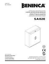
Input/Output functions
(1,2) INPUT 230VAC= Control unit 230VAC 50 Hz power supply
(respect phase/neutral wire position).
(3,4,5) COM/APRE/CHIUDE= Connection to the corresponding 230VAC 50 Hz motor terminals
(the earth wire (green/yellow) must be connected to the motor housing).
(6,7) OUT 24VAC= 24VAC auxiliary power supply output (100mA max.).
(12) +V= Common connection to all the control inputs.
(9) FTC= Photocell receiver input (n.c. contact).
(10) FCA= Input of limit switch APRE (n.c. contact).
(11) FCC= Input of limit switch CHIUDE (n.c. contact).
(8) P.P.= Input, “PASSO-PASSO” push button or “APRE” push-button according to the Dip-Switch
presetting
(15) CHIUDE= CLOSE button input (n.o. contact).
(13,14) ANT.= Input of radio board antenna
N.B.: terminals of the electric lock module
terminal 16 = N.O.
terminal 17 = COM.
terminal 18 = N.C.

7
Dip-switch functions
N.B.: Every change of functions have to be done without electricity.
DSW1= This selects the type of functioning of the P.P. button and Remote control.
Off= ”APRE” - ”STOP” - ”CHIUDE” functioning
On= ”APRE” - ”CHIUDE” - ”APRE” functioning.
DSW2= This enables or disables the automatic re-closing - ”TCA TRIMMER”.
Off= Automatic re-closing enabled
On= Automatic re-closing disabled
DSW3= This enables or disables the apartment building function (after the first opening command, the
P.P. button and the Remote control are deactivated).
Off= Apartment building function disabled.
On= Apartment building function enabled.
DSW4= It selects the operation of the “P.P.” input as push-button “PASSO-PASSO” or push-button
“APRE”.
Off= “P.P.” push-button
On= “APRE” push-button
Trimmer functions
TCA= This allows the automatic re-closing time to be adjusted when this is enabled by positioning the
DSW2 Dip-switch on OFF.
Adjustment can be from a minimum of 5 to a maximum of 150 seconds.
The minimum time is obtained by rotating the trimmer completely clockwise.
TL= This allows the working time of the automation to be adjusted. If the limit switches fail, the soft-
ware protection will intervene after this time has elapsed. (Add about 4 sec. to the actual stroke
time of the automation).
Adjustment can be from a minimum of 7 to a maximum of 180 seconds.
The minimum time is obtained by rotating the trimmer completely clockwise.
Note
• The ”STOP” control can be carried out by connecting the normally closed push button between the
common wire of the limit switch and the ”+V” terminal (see drawing).
• If the ”P.P.” input is used as ”APRE” (Dip-switch 4= ON), the automatic closure is not carried out until
the contact remains closed.
+V
FTC
FCA
FCC
STOP button
Limit switch buttons

AUTOMATISMI PER CANCELLI
®
AUTOMATISMI BENINCÀ Srl - Via Capitello, 45 - 36066 Sandrigo (VI) - Tel. 0444 751030 r.a. - Fax 0444 759728
/