Page is loading ...

MX5102 Instructions
A Complete Power Management, Surge Protection, and Battery Backup Solution
Features:
• Surge Protection and AVM
• LiFT Noise Filtration
• Dual Learning IR Output Controls
• Rack Ears Included
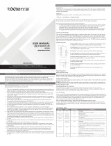
POWER DISPLAY/
UPS TEST
BANKS
1 2 3 4
UNSAFE
VOLTAGE
WIRING
FAULT
MX5102
O VOLTS IN
EST’D BATTERY: 60 MIN
® 2009 Panamax, Inc., 1690 Corporate Circle, Petaluma, CA 94954 • www.panamax.com • 707-283-5900 • Fax 707-283-5901
INS00850-EN REV. D 4/09

Table of Contents
Specifications................................................................................................................................................................................pg. 1
Important Safety Instructions / FCC Notice.......................................................................................................................................pg. 2
Key Features and Functions...........................................................................................................................................................pg. 3
Front and Back Panel Descriptions.................................................................................................................................................pg. 4
Installing Your MX5102 / UPS Operation.........................................................................................................................................pg. 5
Advanced Operation......................................................................................................................................................................pg. 6
Warranty Information.....................................................................................................................................................................pg. 7
In addition to this manual the box should contain the following:
1. UPS Unit
3. Coaxial Cables
2. Rack Mounting Kit
4. RJ-45 Network Cable
Before you begin unpacking inspect the MX5102 upon receipt.
MX5102 Specifications
AC Power
Line Voltage 120V, 60Hz
Total Current Capacity 12 A
Energy Dissipation 1800 Joules
Catastrophic Surge Circuit Yes
Thermal Fusing Yes
Overvoltage Shutoff, fast rise 150 ± 5 V
Overvoltage Shutoff, slow rise 132 ± 5 V
Undervoltage Shutoff 90 ± 5 V
EMI/RFI Noise Filtration
Bank 1 EMI Filtration 66dB Max, 100kHz-2MHz
Bank 2 EMI Filtration 66dB Max, 100kHz-2MHz
UPS Output
Voltage 120 ± 5% Simulated Sine Wave
Frequency 60 Hz ± 1%
UPS Output Capacity 600VA/360W @ 0.6pf
UPS Backup Time 3 minutes at full load
Transfer Time < 10ms
DC Trigger Input
Jacks 3.5mm (1/8”) mono mini-plug
Voltage and Polarity 3 - 18V DC, bidirectional
Current Requirement 4.6 mA @3V, 58 mA @18V
LAN Circuits
Clamping Level 50V
Jacks RJ-45
Wires Protected 8-Wires
Telephone Circuit
Fuseless/Auto-resetting Yes
Clamping Level 275V
Suppression Modes Metallic & Longitudinal
Jacks RJ-11
Wires Protected 2-Wire, Pins 4 & 5
Cable and Satellite Circuits
HD 1080 i/p Ready Yes
Bi-directional Yes
Shielded Yes
Clamping Level 75V
Frequency Range 0MHz - 2.2 GHz
Insertion Loss < 0.5 dB
Connections Female “F”, Gold Plated
Specifications are subject to changes due to product upgrades and improvements.
1
5. RJ-11 Telephone Cable

This manual contains important instructions that should be followed dur-
ing installation and maintenance of the UPS and batteries.
Please read and follow all instructions carefully during installation
and operation of the unit. Read this manual thoroughly before at-
tempting to unpack, install, or operate.
CAUTION! Risk of explosion if battery is replaced ay an incorrect type.
CAUTION! The UPS must be connected to an AC power outlet with fuse or
circuit breaker protection.
DO NOT plug the machine into an outlet that is not grounded. If you need to
de-energize this equipment, turn off and unplug the UPS.
CAUTION! DO NOT USE FOR MEDICAL OR LIFE SUPPORT EQUIPMENT!
Panamax does not sell products for life support or medical applications. DO
NOT use in any circumstance that would affect operation or safety of any life
support equipment, with any medical applications, or patient care.
CAUTION! The battery can energize hazardous live parts inside even when
the AC input power is disconnected.
CAUTION! To prevent the risk of fire or electric shock install in a temperature
and humidity controlled indoor area, free of conductive contaminants. (Please
see specifications for acceptable temperature and humidity range).
2
Important Safety Instructions
CAUTION! To reduce the risk of electric shock, do not remove the cover. No
user serviceable parts inside.
CAUTION! To avoid electrical shock, turn off the unit and unplug it from the
AC power source before servicing the battery or installing a component.
CAUTION! DO NOT USE WITH OR NEAR AQUARIUMS!
To reduce the risk of fire, do not use with or near aquariums. Condensation
from the aquarium can come in contact with metal current contacts and
cause the machine to short out.
Note: AC Power management devices, such as a UPS, have certain limita-
tions with regard to reactive loads and wattage. The MX5102 has a handling
capacity of 600VA or approximately 600 watts. Excessive power consump-
tion beyond these specifications can affect battery life and performance.
For pluggable equipment, the socket shall be installed near the equipment
and shall be easily accessible.
CAUTION: To reduce the risk of fire, connect only to a circuit provided with
a 20 amperes maximum branch circuit overcurrent protection in accordance
with National Electric Code, ANSI / NFPA 70.
To avoid electrical shock, a screwdriver must be used to remove screws to
open battery cover before replacing battery. Must close battery compartment
using screwdriver to tighten screws.
NOTE TO CATV INSTALLERS
This reminder is provided to call attention to Article 820-40 of the
NEC. That article provides specific guidlines for proper grounding. It
specifies that the cable ground shall be connected to the grounding
system of the building and as close to the point of entry as practical.
FCC Notice
FCC Notice
This equipment has been tested and found to comply with the limits for
a Class B Digital Device, pursuant to Part 15 of the FCC Rules. These
limits are designed to provide reasonable protection against harmful
interference in residential installation. This equipment generates, uses,
and can radiate radio frequency energy and, if not installed and used
in accordance with the instructions, may cause harmful interference to
radio communications. However, there is no guarantee that interference
will not occur in a particular installation. If this equipment does cause
harmful interference to radio or television reception, which can be de-
termined by turning the equipment off and on, the user is encouraged to
try to correct the interference by one or more of the following measures:
(1) Reorient or relocate the receiving antenna.
(2) Increase the separation between the equipment and receiver.
(3) Connect the equipment into an outlet on a circuit different from that
to which the receiver is connected.
(4) Consult the dealer or an experienced radio/TV technician for help.
Any special accessories needed for compliance must be specified in the
instruction.
CAUTION: A shielded-type power cord is required in order to meet FCC
emission limits and also to prevent interference to the nearby radio and
television reception. It is essential that only the supplied power cord be
used. Use only shielded cables to connect I/O devices to this equipment.
CAUTION: Any changes or modifications not expressly approved by the
guarantee of this device could void the user’s authority to operate the
equipment.

Sequential Start/Shutdown
Complex audio/video systems may be susceptible to voltage transients
generated internally at start-up/shutdown if all of the equipment is powered
on or off at the same time. This can cause speaker “thumps” which are not
only annoying but can also damage the speakers and or trip product circuit
breakers. The MX5102 is designed to eliminate these transients by providing
a “start-up” delay for the High-Current outlets and a “shutdown” delay for the
Switched Outlet Banks. This minimizes in rush current issues by allowing the
components plugged into the Switched Outlet Banks to power-up and stabilize
before any amplifiers and powered subwoofers are turned on. This sequence
is reversed during shutdown. The amplifiers and powered subwoofers turn off,
their power supplies drain, and then the equipment plugged into the Switched
Outlet Banks are turned off.
Voltage Sense Trigger
The MX5102 voltage sense trigger input uses a standard 3.5mm (1/8”) mini-
mono plug. This feature provides an ON/OFF trigger for the MX5102 using
a Direct Current voltage signal. Many components such as pre-amplifiers
and receivers have a DC trigger built in, and will transmit a constant power
signal when turned on and in use. The presence of this power signal will turn
on the MX5102’s switched outlets. When the source component is turned
off, the voltage trigger signal is also turned off and the MX5102’s shutdown
sequence is initiated. An AC Adapter of the appropriate voltage, plugged into
a switched outlet, may also be used if a DC trigger is not built in. When in use
the Voltage Sense Trigger overrides the function of the on/off power button.
Battery Backup Outlet Bank
Today’s audio/video systems include several components that greatly
benefit from uninterrupted power. Cable boxes and satellite receivers take
a substantial amount of time to recover all of the programming information
after a power failure. DVRs can continue to record scheduled programs.
Projection television bulbs can fail from thermal shock if the power is abruptly
interrupted and the television cannot go through the proper cool down cycle.
MX5102 includes a bank of 2 Uninterruptible Power Supply (UPS) outlets.
Learning IR Control
The learning function lets you program MX5102 to send standby or shut-
down commands to components such as DLP ceiling projectors or rear
projection televisions. For example: if the power fails, the projector’s lamp is
turned off while battery back-up outlets continue to provide battery power to
the projector’s cooling fan. Proper shutdown is ensured and expensive lamps
are protected from damage. The MX5102 can learn up to two discrete IR
commands to send a single command to two devices, or to send a two-
command macro to a single device.
Automatic Over & Under Voltage Protection
Panamax’s power monitoring circuitry constantly monitors the AC line volt-
age for unsafe voltage conditions such as momentary spikes or prolonged
over-voltages and under-voltages (brownouts). These unsafe conditions pose
a very dangerous threat to all electronic equipment within the home. If the
MX5102 senses an unsafe power condition, it will automatically discon-
nect your equipment from the power to protect equipment from damage.
When MX5102 disconnects from the power, the Battery Backup Outlets are
switched to battery power.
3
Key Features and Functions
• When subjected to a 6,000V (open circuit voltage) / 500A (short circuit cur-
rent) surge, the MX5102 limits its voltage output to less than 330V peak, UL’s
best rating. The MX5102 will withstand, without damage, 10,000A surges, far
exceeding the UL requirement of only 3000 Ampere surges.
• If the magnitude of the surge is greater than the capacity of the surge
protection components, the MX5102’s Protect or Disconnect Circuitry will
disconnect your equipment in order to protect it. The MX5102 will need to
be repaired or replaced by Panamax if this occurs within the 3 yr. product
warranty.
Cable/Sat/Antenna Signal Protection
Coaxial protection circuits achieve optimum signal quality from our new
coaxial protectors that have the smallest signal loss on the market - less than
0.5 db of attenuation from 0 MHz to 2.2 GHz. Our upgraded coaxial protection
has been specifically designed to virtually eliminate signal loss. The clamping
level of 75V will meet the demands of both cable and satellite voltage while
minimizing exposure to damaging spikes and surges.
Telephone Line Protection
Digital video recorders and satellite TV receivers require a telephone line con-
nection for TV show scheduling and/or Pay-Per-View services. The MX5102
also provides surge protection for this line. One pair of RJ- 11 telephone jacks
is provided for this. The clamping level of the MX5102 telephone protector is
267 volts. This will allow typical ring voltage (90-130VAC) and operating bat-
tery voltage (-48DC) to pass through the circuit and still protect the modem in
your satellite receiver from damage.
LAN
Protection circuits for 10/100 baseT Ethernet lines. Incoming LAN line
MUST be plugged into the LINE jack. Patch cord to the equipment MUST
be plugged into the EQUIP jacks. 8 wire protection, 50V clamping.
Isolated Banks: LiFT Technology EMI/RFI Noise Filtration with Isola-
tion Between Outlet Banks:
Your audio/video components are constantly being bombarded by electromag-
netic interference (EMI) and radio frequency interference (RFI) through their
AC power source. This contaminated power can affect audio/video equipment
and will degrade the overall performance of your entire system. Common
symptoms of contaminated power include loss of picture detail, dull colors,
pops, hisses, hums and visual artifacts. The MX5102 is designed to eliminate
noise contamination, supply clean power to your system and provide noise iso-
lation between the outlet banks so that any noise created by A/V components
plugged into the MX5102 cannot contaminate the power going to equipment
plugged into the other outlet banks of the MX5102.
Linear Filtering Technology (LiFT)
For improving picture and sound quality nothing filters AC noise better. LiFT
evenly eliminates noise across the entire bandwidth, ensuring peak audio and
video performance by reducing harmonic distortion and improving the signal-
to-noise ratio. With LiFT, you are assured consistent performance and the
highest resolution from any audio or video playback system.

4
Front and Back Panel Descriptions
POWER DISPLAY/
UPS TEST
BANKS
1 2 3 4
UNSAFE
VOLTAGE
WIRING
FAULT
MX5102
O VOLTS IN
EST’D BATTERY: 60 MIN
BANK 4
BATTERY
BACKUP
HIGH
CURRENT
BANK 3
BANK 2 SWITCHED
BANK 2 SWITCHED BANK 1
ALWAYS
ON
IN
12V
TRIGGER
MAIN POWER
120VAC/12A
1 2 3
LAN IN LAN OUT TEL IN TEL OUT
UNIVERSAL COAX PROTECTION
CIRCUIT
BREAKER
UPS
CIRCUIT
BREAKER
MAIN
IR OUT
__
STATUS
_
IR LEARN
_____________
IR INPUT
_
Power Switch
Press the power
button to turn the
unit ON or OFF.
Meter Dimmer /UPS Test Button
A quick press of the button will cycle the
meter and front panel through several
levels of brightness. Press and hold the
button to initiate an UPS test cycle. During
UPS mode, pressing the button will turn off
the internal warning buzzer.
Unsafe Voltage
Indicator
This LED will illumi-
nate in red to warn
the user that an
unsafe voltage level
is occuring.
Removable Battery
Access Panel
Easy to remove for
battery access and
replacement.
Outlet Bank 1
Indicator
Illuminated blue
when outlet bank 1
is always on.
Outlet Bank 2
Indicator
Illuminated blue
when outlet bank 2
is switched on.
Wiring Fault Indicator
This LED will illuminate in red to warn the user that a wiring problem such
as a bad/missing ground or reversed wiring exists within the AC receptacle.
If illuminated, disconnect all equipment and contact an electrician to insure
outlet is properly wired.
Outlet Bank 4
Two always on, battery pow-
ered, surge protected outlets
for connected equipment
ensure temporary uninterrupted
operation of connected equip-
ment during a power failure.
AC Power Cord
IR Control Section
Indicator LED’s – Indicates
status IR Output Jacks –
Standard 1/8” (3.5mm)
mono jack for connection to
an IR flasher (IR flashers not
included)
Circuit Breakers for
Overload Protection
Resettable circuit
breakers provide optimal
overload protection.
Phone Jack
Protection circuit for one standard
telephone or pay-per-view lines.
Phone circuit is auto-resetting. Incom-
ing phone cord MUST be plugged
into the LINE jack. Patch cords to the
equipment (satellite receiver, digital
video recorder, telephone, etc.) MUST
be plugged into the EQUIP jacks.
2-wire protection, 270V clamping.
Outlet Bank 3
Indicator
Illuminated blue
when outlet bank 3
is switched on.
Outlet Bank 4
Indicator
Illuminated blue
when outlet bank 4
is on.
Digital Voltmeter/UPS Status Display
During normal operation, the digital LED voltmeter
indicates the incoming line voltage. If line voltage
drops below 90VAC, or exceeds 132VAC, the Unsafe
Voltage LED will flash, and during battery backup
(UPS) mode the display will indicate the estimated
minutes of battery backup time.
Outlet Bank 2
Four switched outlets with Linear Filtration
Technology (LiFT) controlled by the front panel
Power Button or the DC Trigger input. Bank 2
will turn on immediately and turn off after 5
seconds. Its output is noise isolated from all
other banks.
LAN Jack
Protection circuit for one
10/100 baseT Ethernet line.
Incoming LAN line MUST be
plugged into the LINE jack.
Patch cord to the equipment
MUST be plugged into the
EQUIP jacks. 8 wire protection,
50V clamping.
Outlet Bank 1
Two always on outlets with
Linear Filtration Technology
(LiFT). Power will only be
turned off under a fault con-
dition, or when the Power
Button is switched off. Its
output is noise isolated from
all other outlet banks.
Universal TV Coaxial Jacks
3 pairs of bidirectional protec-
tion circuits optimized for
satellite, cable, and antenna
TV signal lines.
Voltage Sense Trigger Output
3.5mm (1/8”) Mini-Plug jack.
Outlet Bank 3
Two switched, high-current outlets controlled by the
front panel Power Button or the DC Trigger input.
Bank 3 has a 5 second turn on delay and turns off
immediately. The High Current outlet provides power
from a low impedance noise filtration circuit that
does not limit the current to your equipment. Its
output is noise isolated from all other outlet banks.

5
1. The UPS outlets may be used immediately upon receipt. However,
recharging the battery for at least four hours is recommended to ensure
that the battery’s maximum charge capacity is achieved. Charge loss
may occur during shipping and storage. To recharge the battery, simply
leave the unit plugged into an AC outlet. The unit will charge in both the
ON as well as the OFF position.
2. With the unit OFF and unplugged, plug your equipment into the unit’s
rear panel AC outlets. DO NOT plug a space heater, vacuum cleaner,
paper shredder or other large electrical device into the UPS outlets. The
power demands of these devices will overload and possibly damage the
unit.
3. Plug the MX5102 into a 2 pole, 3 wire grounded receptacle (wall
outlet). Make sure the wall branch outlet is protected by a fuse or circuit
breaker and does not service equipment with large electrical demands
(e. g. refrigerator, copier, etc.) Avoid using extension cords. If used, the
extension cord must be UL or CSA Listed, minimum 14 AWG, 3-wire
grounded, and rated for 15 Amps.
Installing Your MX5102
4. Press the latching button to turn the unit on.
5. The rear panel circuit breakers will open and power to the
connected equipment will be turned OFF if an overload is detected.
To correct this, turn the unit off, unplug one piece of equipment from
the UPS outlets, wait 10 seconds, check to make sure that the circuit
breakers are reset, and turn the unit on.
6. The UPS battery will automatically charge whenever the unit is
plugged into an AC outlet.
7. To maintain optimal battery charge, leave the unit plugged into an
AC outlet at all times. Note: To store the MX-5102 for an extended
period, cover it and store with the battery fully charged. Recharge the
battery every three months to ensure battery life.
MX5102 Operation
When power is lost or disconnected for an under/over voltage fault, Outlet
Bank 4 will switch from utility power (power supplied from the power
company) to battery power.
Normal UPS Operation
The display will change from indicating input voltage to the estimated
minutes of backup time. The IR output will activate to trigger required
shutdown sequences in connected devices.
The internal buzzer will sound for 1 second in 5 second intervals. The
buzzer can be turned off by pressing the Meter Dimmer/UPS Test Button.
After power is restored and stabilized, Outlet Bank 4 will automatically
switch back to utility power.
Low Battery Warning
When the battery gets down to 3 minutes of backup time:
the display will flash and the internal buzzer will sound at a quick rate.
When the battery can no longer support the connected load, Outlet Bank
4 is shut off and the buzzer will sound for 5 seconds, one time.
Overload Warning
When the load connected to Outlet Bank 4 exceeds 100% of the rated
power:
The display will flash “OL” (overload)
The internal buzzer will sound at a quick rate
To remedy the overload:
Reduce the load on Outlet Bank 4 by reconnecting one device to an
available outlet in Outlet Bank1 (preferred) or Outlet Bank 2.
Press and hold the Meter Dimmer/UPS Test Button for 2 seconds to
initiate a test of the battery backup. If the load has been reduced to an
acceptable level, MX5102 will return to normal operation.

6
MX5102 Advanced Operation
A connection to a UPS can benefit the volatile electronic memories
found in High-End Home Theater equipment. The MX5102 takes this
to the next level with a number of features designed specifically for AC
Power back up applications.
Patent Pending Learning IR Control
The learning IR function lets you program the MX5102 to send
standby or shut-down commands to components such as DLP ceiling
projectors. If the power fails, the projector’s lamps are turned off while
the UPS continues providing battery power to the projector’s cooling
fan. Proper shutdown is ensured and expensive lamps are protected
from damage. Note: This function should only be used with discrete
IR codes. Programming an On/Off toggle command could result in the
equipment being turned ON during a power failure!
IR Power Failure Operation
The MX5102 can learn two IR commands. The learned commands will
be transmitted on both output jacks so you have the ability to control 2
different pieces of equipment or use a 2-step macro for one compo-
nent.
1. After a power failure, the IR codes will be sent to both outputs after
a 5 second delay. IR code 1 is sent first, followed by IR2 two seconds
later.
2. There is no IR output after the power is restored to the system.
IR LED Color & Status
Off Idle
Green, solid: Waiting to receive IR signal
Green, flashing: IR signal sampled
Red, flashing: Failed to learn IR signal
To program IR output:
1. Press and hold the IR1 button for approximately 2 seconds.
2. When the IR1 LED turns solid GREEN, release the button (after
approx. 2 seconds).
3. Point the remote control at the detector window and quickly press
and release the appropriate button on the remote control. If no signal
is received within 10 seconds, the programming mode is cancelled,
the IR1 LED turns off and you will have to start over.
4. The IR1 LED flashes GREEN if the IR signal is sampled and stored
in memory.
5. The IR1 LED will flash RED if the IR signal was not learned.
Start over at Step 1.
6. Repeat steps 1-5 for IR2.
To clear IR programming:
1. Press and hold the appropriate IR button, release after 2 sec.
2. The IR LED turns solid Green.
3. Press the button again. The IR code will be erased from memory
and the LED will turn off.
IR Output Test
1. An IR flasher must be connected to the UPS and in line-of sight to
the IR receiver window of the equipment to be controlled in order to
verify that the code was learned correctly.
2. Make sure that the component to be controlled is turned ON.
3. Press and release the IR button. The code for IR will be transmitted
on both IR1 and IR2 outputs.
4. If you are testing a 2-step macro, be sure to press the second IR
button to transmit that code.
5. If the learning process was successful, the controlled equipment
should accept the IR command and turn off or go into standby mode.
6. Reprogram the IR command if the controlled equipment does not
respond.
a. Be sure that the batteries in the “teaching remote”
are fresh and do not need to be replaced.
b. If “press & release” (Step 3 in Programming) doesn’t
work, try “press & hold” on the remote control button
being taught to the UPS.

® 2009 Panamax, Inc., 1690 Corporate Circle, Petaluma, CA 94954 • www.panamax.com • 707-283-5900 • Fax 707-283-5901
5. REQUEST PAYMENTS:
Once Panamax has determined that you are entitled to compensation, Panamax will, at its election, ei-
ther pay you the present fair market value of the damaged equipment, or pay for the cost of the repair,
or send you replacement equipment, or pay the equivalence of replacement equipment.
6. OTHER INSURANCE/WARRANTIES: This coverage is secondary to any existing manufacturer’s
warranty, implied or expressed, or any insurance and/or service contract that may cover the loss.
7. EXCLUSIONS: THE PANAMAX CONNECTED EQUIPMENT PROTECTION POLICY DOES NOT
APPLY TO: Service charges, installation costs, reinstallation costs; setup cost; diagnostic charges;
periodic checkups; routine maintenance; loss of use of the product; costs or expenses arising out
of reprogramming or loss of programming and/or data; shipping charges or fees; service calls; loss
or damage occasioned by fire, theft, flood, wind, accident, abuse or misuse, and products subject to
manufacturer’s recall or similar event.
8. DISPUTE RESOLUTION: Any controversy or claim arising out of or relating to Panamax’s Connected
Equipment Protection Policy, or the alleged breach thereof, shall be settled by arbitration administered
by the American Arbitration Association under its Commercial Arbitration Rules. You may file for arbitra-
tion at any AAA location in the United States upon the payment of the applicable filing fee. The arbitra-
tion will be conducted before a single arbitrator, and will be limited solely to the dispute or controversy
between you and Panamax. The arbitration shall be held in any mutually agreed upon location in
person, by telephone, or online. Any decision rendered in such arbitration proceedings will be final and
binding on each of the parties, and judgment may be entered thereon in a court of competent jurisdic-
tion. The arbitrator shall not award either party special, exemplary, consequential, punitive, incidental
or indirect damages, or attorney’s fees. The parties will share the costs of arbitration (including the
arbitrator’s fees, if any) in the proportion that the final award bears to the amount of the initial claim.
9. GENERAL: If you have any questions regarding the product warranty or the connected equipment
protection policy, please contact the Panamax Customer Relations Department at www.panamax.com.
The Limited Product Warranty and Connected Equipment Policy herein supersede all previous warran-
ties and/or Connected Equipment repair/replacement policies.
THE LIMITED PRODUCT WARRANTY IS THE ONLY WARRANTY PROVIDED WITH THIS PANAMAX PROD-
UCT AND ANY OTHER IMPLIED OR EXPRESSED WARRANTIES ARE NON-EXISTENT.
This warranty may not be modified except in writing, signed by an officer of the Panamax Corpora-
tion.
* The use of a Panamax extension cord or equivalent (UL or CSA listed, minimum 14AWG, 3-wire
grounded) will not invalidate the warranty.
** Forms are available on the Panamax web site for requesting RAs and opening a claim for connected
equipment damage.
Warning Notice
WARRANTY LIMITATION FOR INTERNET PURCHASERS
Panamax products purchased through the Internet do not carry a valid Connected Equipment Protec-
tion Policy unless purchased from an Authorized Panamax Internet Dealer! Authorized Panamax Inter-
net Dealers have sufficient expertise to insure warranty compliant installations. For a list of Authorized
Panamax Internet Dealers go to www.panamax.com.
CAUTION: Audio/Video, computer and/or telephone system installations can be very complex systems,
which consist of many interconnected components. Due to the nature of electricity and surges, a single
protector may not be able to completely protect complex installations. In those cases, a systematic
approach using multiple protectors must be employed. Systematic protection requires professional de-
sign. AC power, satellite cables, CATV cables, A/V signal line cables or telephone/network lines entering
the system that do not pass through a Panamax surge protector will render the Panamax connected
equipment protection policy null and void. For additional information on how to protect your system,
please contact Panamax before connecting your equipment to the surge protector.
More detailed information is available at www.panamax.com.
If you have any questions regarding these requirements, please contact Customer Relations.
Panamax Power Conditioner Limited Product Warranty
Panamax warrants to the purchaser of this Panamax audio/video component style power conditioner,
for a period of three (3) years from the date of purchase, that the unit shall be free of defects in
design, material or workmanship, and Panamax will repair or replace any defective unit.
Upgrade Policy
Valid only in the United states and Canada
If your Panamax UPS sacrifices itself while protecting your connected equipment, you have an option to
upgrade to the latest technology. Please go to our web sites www.panamax.com or contact Customer
Relations at 800-472-5555 for details.
2 Year Battery Warranty
Please contact Panamax Customer Service for information regarding battery replacement and 2-year
Battery Warranty.
Panamax Power Conditioner Limited Connected Equipment Protection Policy
It is the policy of Panamax that it will, at its election, either replace, pay to replace at fair market value,
or pay to repair, up to the dollar amount specified below, equipment that is damaged by an AC power,
cable, telephone, or lightning surge while connected to a properly installed Panamax power condi-
tioner. To be eligible for compensation, repair and or replacement, the power conditioner must shows
signs of surge damage or that it is operating outside of design specifications, relative to its surge
protection capability, and under all of the circumstances failed to protect your connected equipment.
MX5102: $5,000,000
THE CONNECTED EQUIPMENT POLICY IS SUBJECT TO THE FOLLOWING CONDITIONS AND
LIMITATIONS
1. ORIGINAL OWNERSHIP REQUIREMENT:
Panamax’s connected equipment policy extends to the original purchaser of the Panamax product only
and is non-transferable. Original purchase receipts must accompany any product return or claim for
connected equipment damage.
2. PROPER INSTALLATION: Panamax AC protectors must be directly plugged into a properly ground-
ed 3-wire AC outlet. Extension cords*, non-grounded two prong adapters, or other non-Panamax
surge products must not be used. Building wiring and other connections to protected equipment
must conform to applicable codes (NEC or CEC). No other ground wires or ground connections may
be used. All wires (including, e.g., AC power lines, telephone lines, signal/data lines, coaxial cable,
antenna lead-ins) leading into the protected equipment must first pass through a single Panamax
protector designed for the particular application. The protector and the equipment to be protected
must be indoors in a dry location, and in the same building. Panamax installation instructions and
diagrams must be followed
3. NOTIFICATION: You must notify Panamax within ten days of any event precipitating request for
product replacement or payment for connected equipment damage. A return authorization (RA) num-
ber must first be obtained from the Panamax Customer Relations Department at www.panamax.com**
before returning the protector Panamax. At this time, you must notify Panamax if you believe you have
a claim for damaged connected equipment. Once you obtain an RA number, please mark the number
on the bottom of the unit and pack it in a shipping carton/box with enough packing material to protect
it during transit. The RA number must also be clearly marked on the outside of the carton. Ship the unit
Panamax. Please note that you are responsible for any and all charges related to shipping the unit to
Panamax. If connected equipment damage was indicated on your RA request, Panamax will mail you
claim kit to be completed and returned within 30 days. A connection diagram of your system will be re-
quired as part of the claim kit. Be sure to note its configuration before disconnecting your equipment.
4. DETERMINATION OF FAILURE: Panamax will evaluate the protector for surge damage. The Pana-
max protector must show signs of surge damage or must be performing outside (>10%) of design
specifications relative to its surge protection capability. Opening the enclosure, tampering with, or
modifying the unit in any way shall be grounds for an automatic denial your request for payment.
Panamax, after evaluating all information provided, will determine whether or not your request is
eligible for payment. If the surge protector shows no signs of AC power or signal line surge damage
and is working within design specifications, Panamax will return the unit to you with a letter explaining
the test results Exceptions: If a dealer or installer replaces the protector for the customer, replacement
will be returned to the dealer installer; or if the protector is a pre-1996 model, it will be replaced; or,
for a Canadian customer, the protector will be replaced. Panamax reserves the right to inspect the
damaged connected equipment, parts, or circuit boards. Please note that you are responsible for any
and all charges related to shipping the damaged equipment to Panamax. Panamax also reserves the
right to inspect the customer’s facility. Damaged equipment deemed uneconomical to repair must
remain available for inspection by Panamax until the claim is finalized.
INS00850-EN REV. D 4/09
7
Warranty Information
MODEL - MX5102
DOC. NO. IWS00850_EN REV. A
Effective Date 1/8/09

MX5102 Instructions
Un completo de administración de energía, protección, y la batería de soluciones de copia de seguridad
Caractéristiques:
• Protection contre les surtensions et AVM
• LiFT Noise Filtration
• Double Filtration bruit apprentissage IR de sortie
• Inclus Rack Ears
POWER DISPLAY/
UPS TEST
BANKS
1 2 3 4
UNSAFE
VOLTAGE
WIRING
FAULT
MX5102
O VOLTS IN
EST’D BATTERY: 60 MIN
® 2009 Panamax, Inc., 1690 Corporate Circle, Petaluma, CA 94954 • www.panamax.com • 707-283-5900 • Fax 707-283-5901
INS00850 REV. D - FR 4/09

Table des matières
Caractéristiques............................................................................................................................................................................pg. 1
Consignes de sécurité / Avis FCC..................................................................................................................................................pg. 2
Principales caractéristiques et fonctions.........................................................................................................................................pg. 3
Front et Back Panel Descriptions....................................................................................................................................................pg. 4
Installation de votre MX5102 / UPS opération..................................................................................................................................pg. 5
Advanced opération.......................................................................................................................................................................pg. 6
Renseignements sur la garantie.....................................................................................................................................................pg. 7
Inspectez bien votre onduleur dès sa réception. Outre ce manuel, l’emballagedoit contenir les éléments suivants :
1. UPS l’onduleur
3. Coaxial câble
2. un kit de montage en baie
4. RJ-45 Network câble
Avant de commencer
MX5102 Spécifications
Alimentation c. a.
Line Voltage 120V, 60Hz
Total Current Capacity 12 A
Dissipation de l’énergie 1800 Joules
Circuit catastrophique Surge Yes
Thermal Fusing Yes
Overvoltage Shutoff, fast rise 150 ± 5 V
Overvoltage Shutoff, slow rise 132 ± 5 V
Undervoltage Shutoff 90 ± 5 V
EMI/RFI Noise Filtration
Bank 1 EMI Filtration 66dB Max, 100kHz-2MHz
Bank 2 EMI Filtration 66dB Max, 100kHz-2MHz
UPS Output
La tension 120 ± 5% Simulated Sine Wave
Frequency 60 Hz ± 1%
UPS Output Capacity 600VA/360W @ 0.6pf
UPS Backup Time 3 minutes at full load
Transfer Time < 10ms
DC Trigger Input
Connexions 3.5mm (1/8”) mono mini-plug
La tension et la polarité 3 - 18V DC, bidirectional
Current Requirement 4.6 mA @3V, 58 mA @18V
LAN Circuits
Clamping Level 50V
Connexions RJ-45
Wires Protected 8-Wires
Telephone Circuit
Fuseless/Auto-resetting Oui
Clamping Level 275V
Suppression Modes Metallic & Longitudinal
Connexions RJ-11
Wires Protected 2-Wire, Pins 4 & 5
Cable and Satellite Circuits
HD 1080 i/p Ready Oui
Bi-directional Oui
Shielded Oui
Clamping Level 75V
Frequency Range 0MHz - 2.2 GHz
Insertion Loss < 0.5 dB
Connexions Female “F”, Gold Plated
Les spécifications sont sujettes à modifications en raison de mises à jour des produits
et des améliorations.
1
5. RJ-11 Telephone câble
/