Page is loading ...

Model 41-818820
Model 41-818820-B
Model 41-818822
Model 41-818823-B
Part Sheet 77-2994
Quality System
ISO9001 Certied
Environmental Management System
ISO14001 Certied
Certied Quality
Binks
195 International Blvd.,
Glendale Heights, IL 60139 USA
Telephone:
1.800.99.BINKS
630.237.5000
Toll Free Customer Service
and Technical Support
800-992-4657
Toll Free Fax
888-246-5732
1: PUMP SPECS2: INSTAL & OP3: EXP VIEW4: AIR END5: WET END6: CERTIFICATES
SERVICE & OPERATING MANUAL
Original Instructions

41-818820.22.23sm-rev0517
IMPORTANT
Read the safety warnings and instructions in this manual
before pump installation and start-up. Failure to comply with
the recommendations stated in this manual could damage the
pump and void factory warranty.
When used for toxic or aggressive uids, the pump should
always be ushed clean prior to disassembly.
Airborne particles and loud noise hazards. Wear eye and ear
protection.
Before maintenance or repair, shut off the compressed air line,
bleed the pressure, and disconnect the air line from the pump.
Be certain that approved eye protection and protective clothing
are worn at all times. Failure to follow these recommendations
may result in serious injury or death.
ATEX compliant pumps are suitable for use in explosive atmospheres when the equipment is properly grounded
in accordance with local electrical codes. Pumps equipped with electrically conductive diaphragms are suitable for
the transfer of conductive or non-conductive uids of any explosion group. When operating pumps equipped with
non-conductive diaphragms that exceed the maximum permissible projected area, as dened in EN 13461-1: 2009
section 6.7.5 table 9, the following protection methods must be applied:
• Equipment is always used to transfer electrically conductive uids or
• Explosive environment is prevented from entering the internal portions of the pump, i.e. dry running
For further guidance on ATEX applications, please consult the factory.
When the pump is used for materials that tend to settle out
or solidify, the pump should be ushed after each use to
prevent damage. In freezing temperatures the pump should be
completely drained between uses.
Before pump operation, inspect all fasteners for loosening
caused by gasket creep. Retighten loose fasteners to prevent
leakage. Follow recommended torques stated in this manual.
CAUTION
WARNING
Nonmetallic pumps and plastic components are not UV
stabilized. Ultraviolet radiation can damage these parts and
negatively affect material properties. Do not expose to UV light
for extended periods of time.
In the event of diaphragm rupture, pumped material may enter
the air end of the pump, and be discharged into the atmosphere.
If pumping a product that is hazardous or toxic, the air exhaust
must be piped to an appropriate area for safe containment.
This pump is pressurized internally with air pressure during
operation. Make certain that all fasteners are in good condition
and are reinstalled properly during reassembly.
Take action to prevent static sparking. Fire or explosion can
result, especially when handling ammable liquids. The pump,
piping, valves, containers and other miscellaneous equipment
must be properly grounded.
Safety Information
Grounding ATEX Pumps
WARNING
Pump not designed, tested or certied to be powered by
compressed natural gas. Powering the pump with natural
gas will void the warranty.
Use safe practices when lifting
kg

41-818820.22.23sm-rev0517
Table of Contents
SECTION 1: PUMP SPECIFICATIONS ................1
• Performance
• Materials
• Dimensional Drawings
SECTION 2: INSTALLATION & OPERATION ......3
• Principle of Pump Operation
• Recommended Installation Guide
• Troubleshooting Guide
SECTION 3: EXPLODED VIEW ...........................6
• Composite Repair Parts Drawing
• Composite Repair Parts List
SECTION 4: AIR END .........................................8
• Air Distribution Valve Assembly
• Pilot Valve Assembly
• Intermediate Assembly
SECTION 5: WET END .....................................11
• Diaphragm Drawings
• Diaphragm Servicing
SECTION 6: CERTIFICATES ............................13
• Warranty and Contact Information
• EC Declaration of Conformity - Machinery
• EC Declaration of Conformity - ATEX
1: PUMP SPECS2: INSTAL & OP3: EXP VIEW4: AIR END5: WET END6: CERTIFICATES

41-818820.22.23sm-rev0517
1
5(8.5)
15(25.5)
20(34)
25(42.5)
0 5 10 15 20
25 30 35 40 45
160140 180120100806040200
100
80
60
40
20
0
0
1
2
3
4
5
6
7
30
20
25
10
15
5
9.1
6
7.6
3
4.5
1.5
50
10(17)
30(51)
35(59.5)
40(68)
CAPACITY
Liters per minute
HEAD
U.S. Gallons per minute
BAR
PSI
NPSHR
METERS
FEET
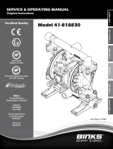
MODEL S1F Metallic Performance Curve
Performance based on the following: elastomer fitted pump, flooded suction, water at ambient conditions.
The use of other materials and varying hydraulic conditions may result in deviations in excess of 5%.
100 PSI (6.8 Bar)
60 PSI (4.08 Bar)
20 PSI (1.36 Bar) Air Inlet Pressure
40 PSI (2.72 Bar)
80 PSI (5.44 Bar)
Performance
SUCTION/DISCHARGE PORT SIZE
• Model 41-818820 & 41-818822
1" NPT (internal)
• Model 41-818820-B & 41-818823-B
1" BSP Tapered (internal)
CAPACITY
• 0 to 45 gallons per minute
(0 to 170 liters per minute)
AIR DISTRIBUTION VALVE
• No-lube, no-stall design
SOLIDS-HANDLING
• Up to .25 in. (6mm)
HEADS UP TO
• 125 psi or 289 ft. of water
(8.6 Kg/cm2 or 86 meters)
DISPLACEMENT/STROKE
• .11 Gallon / .42 liter
MAXIMUM OPERATING PRESSURE
• 125 psi (8.6 bar)
SHIPPING WEIGHT
• Aluminum 28 lbs. (13kg)
• Stainless Steel 43 lbs. (20kg)
Material Prole: Operating
Temperatures:
Max. Min.
Nitrile: General purpose, oil-resistant. Shows good solvent, oil,
water and hydraulic uid resistance. Should not be used with
highly polar solvents like acetone and MEK, ozone, chlorinated
hydrocarbons and nitro hydrocarbons.
190°F
88°C
-10°F
-23°C
Santoprene®: Injection molded thermoplastic elastomer with
no fabric layer. Long mechanical ex life. Excellent abrasion
resistance.
275°F
135°C
-40°F
-40°C
Virgin PTFE: (PFA/TFE) Chemically inert, virtually impervious.
Very few chemicals are known to chemically react with PTFE;
molten alkali metals, turbulent liquid or gaseous uorine and
a few uoro-chemicals such as chlorine triuoride or oxygen
diuoride which readily liberate free uorine at elevated
temperatures.
220°F
104°C
-35°F
-37°C
Maximum and Minimum Temperatures are the limits for which these materials can be operated.
Temperatures coupled with pressure affect the longevity of diaphragm pump components.
Maximum life should not be expected at the extreme limits of the temperature ranges.
Metals:
Stainless Steel: Equal to or exceeding ASTM specication A743 CF-8M for corrosion
resistant iron chromium, iron chromium nickel and nickel based alloy castings for
general applications. Commonly referred to as 316 Stainless Steel in the pump industry.
CAUTION! Operating temperature limitations are as follows:
Ambient temperature range: -20°C to +40°C
Process temperature range: -20°C to +100°C for models rated as category 2 equipment
Materials
1: PUMP SPECS

41-818820.22.23sm-rev0517
2
Dimensions in Inches. Dimensional Tolerance: ±1/8"
Dimensions in Millimeters. Dimensional Tolerance: ± 3mm
Dimensional Drawings
DISCHARGE PORT
1” NPT
SUCTION PORT
1” NPT
AIR INLET
1/2” NPT
WITH 530-033-000
MUFFLER
BOTH SUCTION AND
DISCHARGE PORTS ARE
AVAILABLE WITH
1” BSPT TAPERED THREADS
BOTTOM VIEW
FRONT VIEW
SIDE VIEW
1” NPT EXHAUST PORT
FOR OPTIONAL MUFFLER
STYLES OR PIPING EXHAUST
AIR IN SUBMERGED
APPLICATIONS.
DISCHARGE PORT
1” NPT
SUCTION PORT
1” NPT
AIR INLET
1/2” NPT
WITH 530-033-000
MUFFLER
BOTH SUCTION AND
DISCHARGE PORTS ARE
AVAILABLE WITH
1” BSPT TAPERED THREADS
BOTTOM VIEW
FRONT VIEW SIDE VIEW
1” NPT EXHAUST PORT
FOR OPTIONAL MUFFLER
STYLES OR PIPING EXHAUST
AIR IN SUBMERGED
APPLICATIONS.
1" NPT
or 1" BSP Tapered
EXHAUST PORT
1" NPT
or 1" BSP Tapered
DISCHARGE PORT
1" NPT
or 1" BSP Tapered
DISCHARGE PORT
1" NPT
or 1" BSP Tapered
EXHAUST PORT
(41-818823 STAINLESS STEEL ONLY)
(41-818823 STAINLESS STEEL ONLY)
1: PUMP SPECS

41-818820.22.23sm-rev0517
3
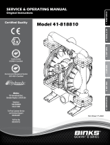
Air-Operated Double Diaphragm (AODD) pumps are powered
by compressed air.
The main directional (air) control valve ① distributes
compressed air to an air chamber, exerting uniform pressure
over the inner surface of the diaphragm
②. At the same time,
the exhausting air ③ from behind the opposite diaphragm
is directed through the air valve assembly(s) to an exhaust
port ④.
As inner chamber pressure (P1) exceeds liquid chamber
pressure (P2), the rod ⑤ connected diaphragms shift
together creating discharge on one side and suction on the
opposite side. The discharged and primed liquid’s directions
are controlled by the check valves (ball or ap)⑥ orientation.
The pump primes as a result of the suction stroke. The
suction stroke lowers the chamber pressure (P3) increasing
the chamber volume. This results in a pressure differential
necessary for atmospheric pressure (P4) to push the uid
through the suction piping and across the suction side check
valve and into the outer uid chamber ⑦.
Suction (side) stroking also initiates the reciprocating
(shifting, stroking or cycling) action of the pump. The suction
diaphragm’s movement is mechanically pulled through its
stroke. The diaphragm’s inner plate makes contact with an
actuator plunger aligned to shift the pilot signaling valve.
Once actuated, the pilot valve sends a pressure signal to the
opposite end of the main directional air valve, redirecting the
compressed air to the opposite inner chamber.
Principle of Pump Operation
Air Line
Discharged
Fluid
Discharge
Stroke Suction
Stroke
Primed
Fluid
2: INSTAL & OP

41-818820.22.23sm-rev0517
4
Principle of Pump Operation
Installation And Start-Up
Locate the pump as close to the product being pumped as possible. Keep the suction line length and number of ttings to a minimum. Do not reduce the suction line
diameter.
Air Supply
Connect the pump air inlet to an air supply with sufcient capacity and pressure to achieve desired performance. A pressure regulating valve should be installed to
insure air supply pressure does not exceed recommended limits.
Air Valve Lubrication
The air distribution system is designed to operate WITHOUT lubrication. This is the standard mode of operation. If lubrication is desired, install an air line lubricator
set to deliver one drop of SAE 10 non-detergent oil for every 20 SCFM (9.4 liters/sec.) of air the pump consumes. Consult the Performance Curve to determine air
consumption.
Air Line Moisture
Water in the compressed air supply may cause icing or freezing of the exhaust air, causing the pump to cycle erratically or stop operating. Water in the air supply can
be reduced by using a point-of-use air dryer.
Air Inlet And Priming
To start the pump, slightly open the air shut-off valve. After the pump primes, the air valve can be opened to increase air ow as desired. If opening the valve
increases cycling rate, but does not increase the rate of ow, cavitation has occurred. The valve should be closed slightly to obtain the most efcient air ow to pump
ow ratio.
Recommended Installation Guide
2: INSTAL & OP

41-818820.22.23sm-rev0517
5
Troubleshooting Guide
Symptom: Potential Cause(s): Recommendation(s):
Pump Cycles Once Deadhead (system pressure meets or exceeds air
supply pressure).
Increase the inlet air pressure to the pump. Pump is designed for 1:1 pressure ratio at zero ow.
(Does not apply to high pressure 2:1 units).
Air valve or intermediate gaskets installed incorrectly. Install gaskets with holes properly aligned.
Bent or missing actuator plunger. Remove pilot valve and inspect actuator plungers.
Pump Will Not Operate
/ Cycle
Pump is over lubricated. Set lubricator on lowest possible setting or remove. Units are designed for lube free operation.
Lack of air (line size, PSI, CFM). Check the air line size and length, compressor capacity (HP vs. CFM required).
Check air distribution system. Disassemble and inspect main air distribution valve, pilot valve and pilot valve actuators.
Discharge line is blocked or clogged manifolds. Check for inadvertently closed discharge line valves. Clean discharge manifolds/piping.
Deadhead (system pressure meets or exceeds air
supply pressure).
Increase the inlet air pressure to the pump. Pump is designed for 1:1 pressure ratio at zero ow.
(Does not apply to high pressure 2:1 units).
Blocked air exhaust mufer. Remove mufer screen, clean or de-ice, and re-install.
Pumped uid in air exhaust mufer. Disassemble pump chambers. Inspect for diaphragm rupture or loose diaphragm plate assembly.
Pump chamber is blocked. Disassemble and inspect wetted chambers. Remove or ush any obstructions.
Pump Cycles and Will
Not Prime or No Flow
Cavitation on suction side. Check suction condition (move pump closer to product).
Check valve obstructed. Valve ball(s) not seating
properly or sticking.
Disassemble the wet end of the pump and manually dislodge obstruction in the check valve pocket.
Clean out around valve ball cage and valve seat area. Replace valve ball or valve seat if damaged.
Use heavier valve ball material.
Valve ball(s) missing (pushed into chamber or
manifold).
Worn valve ball or valve seat. Worn ngers in valve ball cage (replace part). Check Chemical
Resistance Guide for compatibility.
Valve ball(s) / seat(s) damaged or attacked by product. Check Chemical Resistance Guide for compatibility.
Check valve and/or seat is worn or needs adjusting. Inspect check valves and seats for wear and proper setting. Replace if necessary.
Suction line is blocked. Remove or ush obstruction. Check and clear all suction screens or strainers.
Excessive suction lift. For lifts exceeding 20’ of liquid, lling the chambers with liquid will prime the pump in most cases.
Suction side air leakage or air in product. Visually inspect all suction-side gaskets and pipe connections.
Pumped uid in air exhaust mufer. Disassemble pump chambers. Inspect for diaphragm rupture or loose diaphragm plate assembly.
Pump Cycles Running
Sluggish / Stalling,
Flow Unsatisfactory
Over lubrication. Set lubricator on lowest possible setting or remove. Units are designed for lube free operation.
Icing. Remove mufer screen, de-ice, and re-install. Install a point of use air drier.
Clogged manifolds. Clean manifolds to allow proper air ow.
Deadhead (system pressure meets or exceeds air
supply pressure).
Increase the inlet air pressure to the pump. Pump is designed for 1:1 pressure ratio at zero ow.
(Does not apply to high pressure 2:1 units).
Cavitation on suction side. Check suction (move pump closer to product).
Lack of air (line size, PSI, CFM). Check the air line size, length, compressor capacity.
Excessive suction lift. For lifts exceeding 20’ of liquid, lling the chambers with liquid will prime the pump in most cases.
Air supply pressure or volume exceeds system hd. Decrease inlet air (press. and vol.) to the pump. Pump is cavitating the uid by fast cycling.
Undersized suction line. Meet or exceed pump connections.
Restrictive or undersized air line. Install a larger air line and connection.
Suction side air leakage or air in product. Visually inspect all suction-side gaskets and pipe connections.
Suction line is blocked. Remove or ush obstruction. Check and clear all suction screens or strainers.
Pumped uid in air exhaust mufer. Disassemble pump chambers. Inspect for diaphragm rupture or loose diaphragm plate assembly.
Check valve obstructed. Disassemble the wet end of the pump and manually dislodge obstruction in the check valve pocket.
Check valve and/or seat is worn or needs adjusting. Inspect check valves and seats for wear and proper setting. Replace if necessary.
Entrained air or vapor lock in chamber(s). Purge chambers through tapped chamber vent plugs. Purging the chambers of air can be dangerous.
Product Leaking
Through Exhaust
Diaphragm failure, or diaphragm plates loose. Replace diaphragms, check for damage and ensure diaphragm plates are tight.
Diaphragm stretched around center hole or bolt holes. Check for excessive inlet pressure or air pressure. Consult Chemical Resistance Chart for compatibility
with products, cleaners, temperature limitations and lubrication.
Premature Diaphragm
Failure
Cavitation. Enlarge pipe diameter on suction side of pump.
Excessive ooded suction pressure. Move pump closer to product. Raise pump/place pump on top of tank to reduce inlet pressure.
Install Back pressure device (Tech bulletin 41r). Add accumulation tank or pulsation dampener.
Misapplication (chemical/physical incompatibility). Consult Chemical Resistance Chart for compatibility with products, cleaners, temperature limitations
and lubrication.
Incorrect diaphragm plates or plates on backwards,
installed incorrectly or worn.
Check Operating Manual to check for correct part and installation. Ensure outer plates have not been
worn to a sharp edge.
Unbalanced Cycling Excessive suction lift. For lifts exceeding 20’ of liquid, lling the chambers with liquid will prime the pump in most cases.
Undersized suction line. Meet or exceed pump connections.
Pumped uid in air exhaust mufer. Disassemble pump chambers. Inspect for diaphragm rupture or loose diaphragm plate assembly.
Suction side air leakage or air in product. Visually inspect all suction-side gaskets and pipe connections.
Check valve obstructed. Disassemble the wet end of the pump and manually dislodge obstruction in the check valve pocket.
Check valve and/or seat is worn or needs adjusting. Inspect check valves and seats for wear and proper setting. Replace if necessary.
Entrained air or vapor lock in chamber(s). Purge chambers through tapped chamber vent plugs.
2: INSTAL & OP

41-818820.22.23sm-rev0517
6
Troubleshooting Guide
Symptom: Potential Cause(s): Recommendation(s):
Pump Cycles Once Deadhead (system pressure meets or exceeds air
supply pressure).
Increase the inlet air pressure to the pump. Pump is designed for 1:1 pressure ratio at zero ow.
(Does not apply to high pressure 2:1 units).
Air valve or intermediate gaskets installed incorrectly. Install gaskets with holes properly aligned.
Bent or missing actuator plunger. Remove pilot valve and inspect actuator plungers.
Pump Will Not Operate
/ Cycle
Pump is over lubricated. Set lubricator on lowest possible setting or remove. Units are designed for lube free operation.
Lack of air (line size, PSI, CFM). Check the air line size and length, compressor capacity (HP vs. CFM required).
Check air distribution system. Disassemble and inspect main air distribution valve, pilot valve and pilot valve actuators.
Discharge line is blocked or clogged manifolds. Check for inadvertently closed discharge line valves. Clean discharge manifolds/piping.
Deadhead (system pressure meets or exceeds air
supply pressure).
Increase the inlet air pressure to the pump. Pump is designed for 1:1 pressure ratio at zero ow.
(Does not apply to high pressure 2:1 units).
Blocked air exhaust mufer. Remove mufer screen, clean or de-ice, and re-install.
Pumped uid in air exhaust mufer. Disassemble pump chambers. Inspect for diaphragm rupture or loose diaphragm plate assembly.
Pump chamber is blocked. Disassemble and inspect wetted chambers. Remove or ush any obstructions.
Pump Cycles and Will
Not Prime or No Flow
Cavitation on suction side. Check suction condition (move pump closer to product).
Check valve obstructed. Valve ball(s) not seating
properly or sticking.
Disassemble the wet end of the pump and manually dislodge obstruction in the check valve pocket.
Clean out around valve ball cage and valve seat area. Replace valve ball or valve seat if damaged.
Use heavier valve ball material.
Valve ball(s) missing (pushed into chamber or
manifold).
Worn valve ball or valve seat. Worn ngers in valve ball cage (replace part). Check Chemical
Resistance Guide for compatibility.
Valve ball(s) / seat(s) damaged or attacked by product. Check Chemical Resistance Guide for compatibility.
Check valve and/or seat is worn or needs adjusting. Inspect check valves and seats for wear and proper setting. Replace if necessary.
Suction line is blocked. Remove or ush obstruction. Check and clear all suction screens or strainers.
Excessive suction lift. For lifts exceeding 20’ of liquid, lling the chambers with liquid will prime the pump in most cases.
Suction side air leakage or air in product. Visually inspect all suction-side gaskets and pipe connections.
Pumped uid in air exhaust mufer. Disassemble pump chambers. Inspect for diaphragm rupture or loose diaphragm plate assembly.
Pump Cycles Running
Sluggish / Stalling,
Flow Unsatisfactory
Over lubrication. Set lubricator on lowest possible setting or remove. Units are designed for lube free operation.
Icing. Remove mufer screen, de-ice, and re-install. Install a point of use air drier.
Clogged manifolds. Clean manifolds to allow proper air ow.
Deadhead (system pressure meets or exceeds air
supply pressure).
Increase the inlet air pressure to the pump. Pump is designed for 1:1 pressure ratio at zero ow.
(Does not apply to high pressure 2:1 units).
Cavitation on suction side. Check suction (move pump closer to product).
Lack of air (line size, PSI, CFM). Check the air line size, length, compressor capacity.
Excessive suction lift. For lifts exceeding 20’ of liquid, lling the chambers with liquid will prime the pump in most cases.
Air supply pressure or volume exceeds system hd. Decrease inlet air (press. and vol.) to the pump. Pump is cavitating the uid by fast cycling.
Undersized suction line. Meet or exceed pump connections.
Restrictive or undersized air line. Install a larger air line and connection.
Suction side air leakage or air in product. Visually inspect all suction-side gaskets and pipe connections.
Suction line is blocked. Remove or ush obstruction. Check and clear all suction screens or strainers.
Pumped uid in air exhaust mufer. Disassemble pump chambers. Inspect for diaphragm rupture or loose diaphragm plate assembly.
Check valve obstructed. Disassemble the wet end of the pump and manually dislodge obstruction in the check valve pocket.
Check valve and/or seat is worn or needs adjusting. Inspect check valves and seats for wear and proper setting. Replace if necessary.
Entrained air or vapor lock in chamber(s). Purge chambers through tapped chamber vent plugs. Purging the chambers of air can be dangerous.
Product Leaking
Through Exhaust
Diaphragm failure, or diaphragm plates loose. Replace diaphragms, check for damage and ensure diaphragm plates are tight.
Diaphragm stretched around center hole or bolt holes. Check for excessive inlet pressure or air pressure. Consult Chemical Resistance Chart for compatibility
with products, cleaners, temperature limitations and lubrication.
Premature Diaphragm
Failure
Cavitation. Enlarge pipe diameter on suction side of pump.
Excessive ooded suction pressure. Move pump closer to product. Raise pump/place pump on top of tank to reduce inlet pressure.
Install Back pressure device (Tech bulletin 41r). Add accumulation tank or pulsation dampener.
Misapplication (chemical/physical incompatibility). Consult Chemical Resistance Chart for compatibility with products, cleaners, temperature limitations
and lubrication.
Incorrect diaphragm plates or plates on backwards,
installed incorrectly or worn.
Check Operating Manual to check for correct part and installation. Ensure outer plates have not been
worn to a sharp edge.
Unbalanced Cycling Excessive suction lift. For lifts exceeding 20’ of liquid, lling the chambers with liquid will prime the pump in most cases.
Undersized suction line. Meet or exceed pump connections.
Pumped uid in air exhaust mufer. Disassemble pump chambers. Inspect for diaphragm rupture or loose diaphragm plate assembly.
Suction side air leakage or air in product. Visually inspect all suction-side gaskets and pipe connections.
Check valve obstructed. Disassemble the wet end of the pump and manually dislodge obstruction in the check valve pocket.
Check valve and/or seat is worn or needs adjusting. Inspect check valves and seats for wear and proper setting. Replace if necessary.
Entrained air or vapor lock in chamber(s). Purge chambers through tapped chamber vent plugs.
41-718855 Air Motor Repair Kit
Bumpers, Bushings, Gaskets, O-rings, Retaining Rings,
and Seals
41-718856 Diaphragm Kits
Synthesis One-Piece Diaphragms, PTFE Manifolds
O-rings, FEP - Encapsulated FKM O-rings for metal
check valve seats
41-718857 Ball and Seat Kit
316 Stainless Steel Check Balls, 316 Stainless Steel
Check Valve Seats, FEP-Encapsulated FKM O-rings for
metal check valce seats
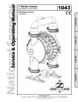
Composite Repair Parts Drawing
Available Service Kits
29
2
10
9
11
12
16
1
19 30
29
2
13
30
9
20
8
18
4
17
5
14
23
6
27
21
7
26
28
3
25
31
32
22
22
22
22
Torque
90 in/lbs.
Torque
90 in/lbs.
3: EXP VIEW

41-818820.22.23sm-rev0517
7
Composite Repair Parts List
Item Description Qty
1 Air Valve Assembly 1
2 Ball, Check 4
4 Pilot Valve Assembly 1
5 Intermediate 1
6 Bumper 2
7 Bushing 2
8 Cap, Air Inlet Assembly 1
9 Capscrew, Hex Hd 5/16-18 X 1.00 16
10 Capscrew, Hex Hd 5/16-18 X 1.25 16
11 Capscrew, Hex Hd 5/16-18 X 1.75 4
12 Capscrew, Hex HD 3/8-16 X 1.00 4
13 Chamber, Outer 2
14 Diaphragm, Synthesis One-Piece 2
16 Gasket, Air Valve 1
17 Gasket, Pilot Valve 1
18 Gasket, Air Inlet Cap 1
19 Manifold, Suction 1
20 Manifold, Discharge 1
21 O-Ring 2
22 O-Ring 8
23 Plate, Inner Diaphragm 2
25 Pin, Actuator 2
26 Ring, Retaining 2
27 Rod, Diaphragm 1
28 Seal, U-Cup 2
29 Seat, Check Ball 4
30 Lock Washer, 5/16 16
31 Flat Washer, 5/16 4
32 Mufer, Metal 1
LEGEND:
= Items contained within 41-718855 Air Motor Repair Kits
= Items contained within 41-718856 Diaphragm Kits
= Items contained within 41-718857 Ball and Seat Kits
3: EXP VIEW

41-818820.22.23sm-rev0517
8
Air Distribution Valve Assembly
IMPORTANT
Read these instructions completely, before installation
and start-up. It is the responsibility of the purchaser
to retain this manual for reference. Failure to comply
with the recommendations stated in this manual will
damage the pump, and void factory warranty.
Air Valve Assembly Parts List
Item Description Qty
1 Air Valve Assembly 1
1-A Body, Air Valve 1
1-B Sleeve and Spool Set 1
1-C Bumper 2
1-D O-Ring 10
1-E Cap, End 2
1-F Hex Head Capscrew
1/4-20 x .75 8
Air Distribution Valve Servicing
See repair parts drawing, remove screws.
Step 1: Remove hex cap screws (1-F).
Step 2: Remove end cap (1-E) and bumper (1-C).
Step 3: Remove spool part of (1-B) (caution: do not scratch).
Step 4: Press sleeve (1-B) from body (1-A).
Step 5: Inspect O-Rings (1-D) and replace if necessary.
Step 6: Lightly lubricate O-Rings (1-D) on sleeve (1-B).
Step 7: Press sleeve (1-B) into body (1-A).
Step 8: Reassemble in reverse order, starting with step 3.
Note: Sleeve and spool (1-B) set is match ground to a specied clearance
sleeve and spools (1-B) cannot be interchanged.
LEGEND:
= Items contained within 41-718850 Air Motor Repair Kits
4: AIR END

41-818820.22.23sm-rev0517
9
Pilot Valve Assembly
Pilot Valve Servicing
With Pilot Valve removed from pump.
Step 1: Remove snap ring (4-F).
Step 2: Remove sleeve (4-B), inspect O-Rings (4-C),
replace if required.
Step 3: Remove spool (4-D) from sleeve (4-B),
inspect O-Rings (4E), replace if required.
Step 4: Lightly lubricate O-Rings (4-C) and (4-E).
Reassemble in reverse order.
Pilot Valve Assembly Parts List
Item Description Qty
4 Pilot Valve Assembly 1
4-A Valve Body 1
4-B Sleeve (With O-Rings) 1
4-C O-Ring (Sleeve) 6
4-D Spool (With O-Rings) 1
4-E O-Ring (Spool) 3
4-F Retaining Ring 1
2-A
2-B
2-C
2-F
2-E 2-D
LEGEND:
= Items contained within 41-718850 Air Motor Repair Kits
4: AIR END

41-818820.22.23sm-rev0517
10
Pilot Valve Assembly Intermediate Assembly
IMPORTANT
When the pumped product source is at a higher
level than the pump (ooded suction condition),
pipe the exhaust higher than the product source
to prevent siphoning spills. In the event of a
diaphragm failure a complete rebuild of the
center section is recommended.
25
21 7
26
5
Intermediate Assembly Parts List
Item Description Qty
5 Intermediate 1
Intermediate 1
7 Bushing, Plunger* 2
21 O-Ring 2
25 Plunger, Actuator* 2
26 Ring, Retaining 2
28 Seal, Diaphragm Rod* 2
Intermediate Assembly Drawing
Step 1: Remove plunger, actuator (25) from center of
intermediate pilot valve cavity.
Step 2: Remove Ring, Retaining (26), discard.
Step 3: Remove bushing, plunger (7), inspect for wear
and replace if necessary with genuine parts.
Step 4: Remove O-Ring (21), inspect for wear and
replace if necessary with genuine parts.
Step 5: Lightly lubricate O-Ring (21) and insert into
intermediate.
Step 6: Utilizing a new Ring, Retaining (26) reassemble
in reverse order
Step 7: Remove Seal, Diaphragm Rod (28).
Step 8: Clean seal area, lightly lubricate and install new Seal,
Diaphragm Rod (28).
LEGEND:
= Items contained within 41-718850 Air Motor Repair Kits
4: AIR END

41-818820.22.23sm-rev0517
11
10
13
5
14
23
6
27
Diaphragm Service Drawing, with Overlay
5: WET END

41-818820.22.23sm-rev0517
12
Step 1: With manifolds and outer chambers
removed, remove diaphragm assemblies from
diaphragm rod. DO NOT use a pipe wrench or similar
tool to remove assembly from rod. Flaws in the rod
surface may damage bearings and seal. Soft jaws
in a vise are recommended to prevent diaphragm
rod damage.
Step 1.A: NOTE: Not all inner diaphragm plates
are threaded. Some models utilize a through hole
in the inner diaphragm plate. If required to separate
diaphragm assembly, place assembly in a vise,
gripping on the exterior cast diameter of the inner
plate. Turn the outer plate clockwise to separate the
assembly.
Always inspect diaphragms for wear cracks or
chemical attack. Inspect inner and outer plates for
deformities, rust scale and wear. Inspect intermediate
bearings for elongation and wear. Inspect diaphragm
rod for wear or marks.
Clean or repair if appropriate. Replace as required.
Step 2: Reassembly: There are two different types
of diaphragm plate assemblies utilized throughout the
Sandpiper product line: Outer plate with a threaded
stud, diaphragm, and a threaded inner plate.
Outer plate with a threaded stud, diaphragm, and
an inner plate with through hole. Secure threaded
inner plate in a vise. Ensure that the plates are being
installed with the outer radius against the diaphragm.
Step 3: Lightly lubricate, with a compatible material,
the inner faces of both outer and inner diaphragm plates
when using on non Overlay diaphragms (For EPDM
water is recommended). No lubrication is required.
Step 4: Push the threaded outer diaphragm
plate through the center hole of the diaphragm.
Note: Most diaphragms are installed with the
natural bulge out towards the fluid side. S05,
S07, and S10 non–metallic units are installed
with the natural bulge in towards the air side.
Step 5: Thread or place, outer plate stud into
the inner plate. For threaded inner plates, use a
torque wrench to tighten the assembly together.
Torque values are called out on the exploded view.
Repeat procedure for second side assembly.
Allow a minimum of 15 minutes to elapse after
torquing, then re-torque the assembly to compensate
for stress relaxation in the clamped assembly.
Step 6: Thread one assembly onto the diaphragm
rod with sealing washer (when used) and bumper.
Step 7: Install diaphragm rod assembly
into pump and secure by installing the outer
chamber in place and tightening the capscrews.
Step 8: On opposite side of pump, thread the
remaining assembly onto the diaphragm rod. Using a
torque wrench, tighten the assembly to the diaphragm
rod. Align diaphragm through bolt holes, always going
forward past the recommended torque. Torque values
are called out on the exploded view. NEVER reverse
to align holes, if alignment cannot be achieved
without damage to diaphragm, loosen complete
assemblies, rotate diaphragm and reassemble as
described above.
Diaphragm Servicing
IMPORTANT
Read these instructions completely,
before installation and start-up.
It is the responsibility of the
purchaser to retain this manual for
reference. Failure to comply with
the recommendations stated in this
manual will damage the pump, and
void factory warranty.
5: WET END

5-YEAR
Limited Product Warranty
Binks® manufacturing warrants to the original end-use purchaser that no product sold by Binks shall fail under normal use and
service due to a defect in material or workmanship within five years from the date of shipment from Binks factory.
See complete warranty at www.binks.com
Binks European Sales and Service Listing: www.nishingbrands.eu
Binks has authorized distributors throughout the world. For technical assistance or the distributor nearest you, see listing below.
For Model: 41-818820-B and 41-818823-B
Finishing Brands (UK) Limited:
Ringwood Road, Bournemouth
Dorest BH11 9LH. UK
Tel. +44 (0) 1202 571 111
Fax +44 (0) 1202 573 488
General e-mail: info@nishingbrands.eu
Surfaces et Finitions:
163-171 Av. des Auréats
26014 Valence cedex. FR
Téléphone. +33 (0) 4 75 75 27 53
Télécopie +33 (0) 4 75 75 27 79
General e-mail: info@nishingbrands.eu
Finishing Brands Germany GmƅH:
Justus-von-Liebig-Straße 31
63128 Dietzenbach. DE
Tel. +49 (0) 6074 403 1
Fax +49 (0) 607 403 300
General e-mail: info@nishingbrands.eu
For Models: 41-818820 and 41-818822
U.S.A./Canada Customer Service
195 Internationale Blvd
Glendale Heights, IL 60139
Tel. 630-237-5000
Fax 630-237-5011
Toll Free Customer Service
and Technical Support
800-992-4657
Toll Free Fax
888-246-5732
Binks Sales and Service: www.binks.com
Warranty Information
Contact Information

Declaration of Conformity
Signature of authorized person Date of issue
Printed name of authorized person
Revision Level: F
Title
Engineering Manager
Charles W. McCulloch
June 8, 2012
April 4, 2013
Date of revision
BINKS, 195 International Blvd, Glendale Heights, IL 60139
Certifies that BINKS models: 41-818810, 41-818810-B, 41-818820, 41-818820-B,
41-818822, 41-818830, 41-818830-B, 41-818831, 41-818831-B,
41-818823-B, 41-818836, 41-818836-B Air-Operated Double Diaphragm
Pump comply with the European Community Directive 2006/42/EC on Machinery,
according to Annex VIII. This product has used Harmonized Standard
EN809:1998+A1:2009, Pumps and Pump Units for Liquids -
Common Safety Requirements, to verify conformance.
6: CERTIFICATES

The objective of the declaration decribed is in conformity
with the relevant Union harmonisation legislation:
Directive 94/9/EC (until April 19, 2016) and Directive 2014/34/EU (from April 20, 2016).
AODD Pumps (Air Operated Double Diaphragm Pumps)
Directive: 94/9/EC, Annex VIII
Technical File: 203104000-1410/MER
Manufacturer:
BINKS
196 International Blvd
Glendale Heights, IL 60139
Applicable Standard:
EN13463-1: 2009
EN13463-5: 2011
DEKRA Certification B.V. (0344)
Meander 1051
6825 MJ Arnhem
The Netherlands
EC / EU Declaration of Conformity
DATE/APPROVAL/TITLE:
Charles W. McCulloch, Engineering ManagerApril 26, 2016
Revision: A
Revision Date: April 26, 2016
II 2 G c T5
II 2 D c T100°C
6: CERTIFICATES
/