Page is loading ...

OPERATOR’S MANUAL 81882X
INCLUDING: OPERATION, INSTALLATION AND MAINTENANCE RELEASED: 8-20-99
REVISED: 11-9-18
(REV: K)
1” DIAPHRAGM PUMP
1:1 RATIO (METALLIC)
READ THIS MANUAL CAREFULLY BEFORE INSTALLING,
OPERATING OR SERVICING THIS EQUIPMENT.
It is the responsibility of the employer to place this information in the hands of the operator. Keep for future reference.
CCN 99866683
U.S.A. / Canada Customer Service Toll Free Customer Service
195 Internationale Blvd and Technical Support
Glendale Heights, IL 60139 800-992-4657
Tel. 630-237-5000 Toll Free Fax
Fax. 630-237-5011 888-246-5732
SERVICE KITS
Refer to the “Model Description Chart” to match the pump material
options.
862003 for Air Section repair (see page 7).
862020 for replacement of Diaphragms (see page 4).
862025 for replacement of Balls and Seats (see page 4).
862026 (optional) for replacement of Balls and Seats (see page 4).
PUMP DATA
Models ............................ see “Model
Description Chart”
Pump Type ....................... Metallic Air Operated
Double Diaphragm
Material ........................... see “Model
Description Chart”
Weight
Aluminum ....................... 19 lbs (8.62 kgs)
Stainless Steel ................... 28.95 lbs (13.13 kgs)
Maximum Air Inlet Pressure ...... 120 psig (8.3 bar)
Maximum Material Inlet Pressure . 10 psig (0.69 bar)
Maximum Outlet Pressure ....... 120 psig (8.3 bar)
Maximum Flow Rate (ooded inlet) ... 35 gpm (133 lpm)
Maximum Particle Size ........... 1/8” dia. (3.2 mm)
Dimensional Data ................. see page 9 and 10
Noise Level @ 70 psig, 60 cpm .. 64.5 dB(A)
Tested with 873275 muer installed.
The pump sound pressure levels published here have been updated to an Equivalent Contin-
uous Sound Level (LA
eq
) to meet the intent of ANSI S1.13-1971, CAGI-PNEUROP S5.1 using four
microphone locations.
GENERAL DESCRIPTION
The Bink’s Diaphragm Pump oers high volume delivery even
at low air pressure. Bink’s pumps feature stall resistant design,
modular air motor / uid sections.
Air operated double diaphragm pumps utilize a pressure
dierential in the air chambers to alternately create suction
and positive uid pressure in the uid chambers, Ball checks
ensure a positive ow of uid. Pump cycling will begin as air
pressure is applied and it will continue to pump and keep up
with the demand. It will build and maintain line pressure and
will stop cycling once maximum line pressure is reached (dis-
pensing device closed) and will resume pumping as needed.
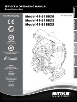
81882X
1’’ DIAPHRAGM PUMP
STAINLESS STEEL
PUMP
ALUMINUM PUMP
Figure 1
MODEL DESCRIPTION CHART
81882
CENTER BODY MATERIAL
FLUID CAP / MANIFOLD MATERIAL, THREADS
- Aluminum
SEAT MATERIAL
- 316 Stainless Steel
- Stainless Steel
- PTFE (Optional kit)
BALL MATERIAL
0 - Aluminum, N.P.T.F. - 1
1 - Aluminum, B.S.P.
2 - Stainless Steel, N.P.T.F. - 1
3 - Stainless Steel, B.S.P.
DIAPHRAGM MATERIAL - PTFE / Santoprene
X

Page 2 of 12 81882X (en)
READ, UNDERSTAND, AND FOLLOW THIS INFORMATION TO AVOID INJURY AND PROPERTY DAMAGE.
OPERATING AND SAFETY PRECAUTIONS
EXCESSIVE AIR PRESSURE
STATIC SPARK
HAZARDOUS MATERIALS
HAZARDOUS PRESSURE
WARNING
EXCESSIVE AIR PRESSURE. Can cause personal
injury, pump damage or property damage.
yDo not exceed the maximum inlet air pressure as stated on
the pump model plate.
yBe sure material hoses and other components are able to
withstand fluid pressures developed by this pump. Check
all hoses for damage or wear. Be certain dispensing device
is clean and in proper working condition.
WARNING
STATIC SPARK. Can cause explosion resulting
in severe injury or death. Ground pump and pumping
system.
ySparks can ignite ammable material and vapors.
yThe pumping system and object being sprayed must be
grounded when it is pumping, flushing, recirculating or
spraying ammable materials such as paints, solvents, lac-
quers, etc. or used in a location where surrounding atmo-
sphere is conducive to spontaneous combustion. Ground
the dispensing valve or device, containers, hoses and any
object to which material is being pumped.
yUse the pump grounding screw terminal provided. Use
Bink’s part no. 873067 Ground Kit or connect a suitable
ground wire (12 ga. minimum) to a good earth ground
source.
ySecure pump, connections and all contact points to avoid
vibration and generation of contact or static spark.
yConsult local building codes and electrical codes for specic
grounding requirements.
yAfter grounding, periodically verify continuity of electrical
path to ground. Test with an ohmmeter from each compo-
nent (e.g., hoses, pump, clamps, container, spray gun, etc.)
to ground to ensure continuity. Ohmmeter should show 0.1
ohms or less.
ySubmerse the outlet hose end, dispensing valve or device
in the material being dispensed if possible. (Avoid free
streaming of material being dispensed.)
yUse hoses incorporating a static wire.
yUse proper ventilation.
yKeep inflammables away from heat, open flames and
sparks.
yKeep containers closed when not in use.
WARNING
PUMP EXHAUST may contain ontaminants.
Can cause severe injury. Pipe exhaust away from work area
and personnel.
yIn the event of a diaphragm rupture, material can be forced
out of the air exhaust muer.
yPipe the exhaust to a safe remote location when pumping
hazardous or inammable materials.
yUse a grounded 3/8” minimum ID hose between the pump
and the muer.
WARNING
HAZARDOUS PRESSURE. Can result in serious
injury or property damage. Do not service or clean pump,
hoses or dispensing valve while the system is pressurized.
yDisconnect air supply line and relieve pressure from the
system by opening dispensing valve or device and / or
carefully and slowly loosening and removing outlet hose or
piping from pump.
WARNING
HAZARDOUS MATERIALS. Can cause serious
injury or property damage. Do not attempt to return
a pump to the factory or service center that contains
hazardous material. Safe handling practices must comply
with local and national laws and safety code requirements.
yObtain Material Safety Data Sheets on all materials from
the supplier for proper handling instructions.
WARNING
EXPLOSION HAZARD. Models containing
aluminum wetted parts cannot be used with III.-
Trichloroethane, methylene chloride or other halogenated
hydrocarbon solvents which may react and explode.
yCheck pump motor section, fluid caps, manifolds and all
wetted parts to assure compatibility before using with sol-
vents of this type.
CAUTION
Verify the chemical compatibility of the pump
wetted parts and the substance being pumped, flushed
or recirculated. Chemical compatibility may change with
temperature and concentration of the chemical(s) within
the substances being pumped, flushed or circulated.
Consult Bink’s representative for information on chemical
compatibility.
CAUTION
Maximum temperatures are based on
mechanical stress only. Certain chemicals will signicantly
reduce maximum safe operating temperature. Consult
Bink’s representative for information on chemical
compatibility. Refer to PUMP DATA on page 1 of this
manual.
CAUTION
Be certain all operators of this equipment
have been trained for safe working practices, understand
it’s limitations, and wear safety goggles / equipment when
required.
CAUTION
Do not use the pump for the structural
support of the piping system. Be certain the system
components are properly supported to prevent stress on
the pump parts.
ySuction and discharge connections should be exible con-
nections (such as hose), not rigid piped, and should be com-
patible with the substance being pumped.
CAUTION
Prevent unnecessary damage to the pump. Do
not allow pump to operate when out of material for long
periods of time.
yDisconnect air line from pump when system sits idle for
long periods of time.
CAUTION
Use only genuine Binks replacement parts to
assure compatible pressure rating and longest service life.
WARNING
=Hazards or unsafe practices which could
result in severe personal injury, death or
substantial property damage.
CAUTION
=Hazards or unsafe practices which could
result in minor personal injury, product
or property damage.
NOTICE
=Important installation, operation or
maintenance information.

81882X (en) Page 3 of 12
y Santoprene® is a registered trademark of Monsanto Company, licensed to Advanced Elastomer Systems, L.P. y Key-Lube® is a registered trademark of Key Industries y
AIR AND LUBE REQUIREMENTS
WARNING
EXCESSIVE AIR PRESSURE. Can cause per-
sonal injury, pump damage or property damage.
yA filter capable of filtering out particles larger than 50
microns should be used on the air supply. There is no lu-
brication required other than the “O” ring lubricant which
is applied during assembly or repair.
yIf lubricated air is present,make sure that it is compatible
with the Nitrile “O” rings in the air motor section of the
pump.
OPERATING INSTRUCTIONS
yAlways flush the pump with a solvent compatible with
the material being pumped if the material being pumped
is subject to “setting up” when not in use for a period of
time.
yDisconnect the air supply from the pump if it is to be in-
active for a few hours.
yThe outlet material volume is governed not only by the air
supply, but also by the material supply available at the in-
let. The material supply tubing should not be too small or
restrictive. Be sure not to use hose which might co lapse.
yWhen the diaphragm pump is used in a forced-feed
(ooded inlet) situation, it is recommended that a “Check
Valve” be installed at the air inlet.
ySecure the diaphragm pump legs to a suitable surface to
ensure against damage by vibration.
MAINTENANCE
Refer to the part views and descriptions as provided on pag-
es 4 through 8 for parts identication and service kit informa-
tion.
yService kits are divided to service two separate dia-
phragm pump functions: 1. AIR SECTION, 2. DIAPHRAGM
SECTION, 3. BALL and SEAT SECTION.
yProvide a clean work surface to protect sensitive internal
moving parts from contamination from dirt and foreign
matter during service disassembly and reassembly.
yKeep good records of service activity and include pump
in preventive maintenance program.
yBefore disassembling, empty captured material in the
outlet manifold by turning the pump upside down to
drain material from the pump.
FLUID SECTION DISASSEMBLY
1. Remove (16) manifolds for aluminum pump and (60, 61)
inlet and outlet manifold for stainless steel pump.
2. Remove (22) balls, (19) “O” rings and (21) seats.
3. Remove (15) uid caps.
4. Remove the (14) screws, (7/8) diaphragms and (5) washers.
5. Remove (3) “O” rings.
NOTE: Do not scratch or mar the surface of (1) diaphragm
rod.
FLUID SECTION REASSEMBLY
yReassemble in reverse order.
yClean and inspect all parts. Replace worn or damaged
parts with new parts as required.
yLubricate (1) diaphragm rod and (2) “O” ring with Key-
Lube grase and install (2) “O” ring on (1) diaphragm rod.
yBe certain (7/8) diaphragm(s) align properly with (15) uid
caps before making nal torque adjustments on bolt and
nuts to avoid twisting the diaphragm.
yFor models with PTFE diaphragms: Item (8) Santoprene
diaphragm is installed with the side marked “AIR SIDE”
towards the pump center body. Install the PTFE dia-
phragm with the side marked “FLUID SIDE” towards the
uid cap.
yRe-check torque settings after pump has been re-started
and run a while.

Page 4 of 12 81882X (en)
FLUID SECTION SERVICE KITS
862020 Diaphragms Kits include: Items 7 and 8 Diaphragms, plus “O” ring items: 2, 3, 19 and Key-Lube grease packet.
□ 862025 Ball and Seat Repair Kits include:
(standard stainless steel ball and seat)
◆ 862026 Ball and Seat Repair Kits include:
(optional PTFE ball and stainless steel seat)
WETTED COMMON PARTS
ALUMINUM
818820, 818821
STAINLESS STEEL
818822, 818823
Item Description (Size) Qty Part No. [Mtl] Part No. [Mtl]
1Rod (1) 873005 [C] 873005 [C]
2 ‘‘O” Ring (3/32” x 3/4” OD) (1) [B] [B]
3 ‘‘O” Ring (1/16” x 5/8” OD) (4) [T] [T]
5 Washer - Air Side (3 - 5/8" OD) (2) 873638 [C] 873638 [C]
6 Washer - Fluid Side (3 - 5/8" OD) (2) 873283 [SS] 873283 [SS]
7 Diaphragm (2) [T] [T]
8 Diaphragm (2) [SP] [Sp]
9 Washer (0.505” ID) (2) 873262 [SS] 873262 [SS]
14 Screw (1/2 - 20 x1”) (2) [SS] [SS]
15 Fluid Cap (2) 873285 [A] 873628 [SS]
16 Manifold (N.P.T.F. -1 threads) (2) 873021 [A] - - - - - -
Manifold (B.S.P. threads) (2) 873022 [A] - - - - - -
◆
19 ‘‘O” Ring (3/32” x 1-9/16” OD) (4) [T] [T]
◆
21 Seat (4) [SS] [SS]
◆
22 Ball (1” dia.) (4) [SS] [SS]
Ball (1” dia.) (4) [T] [T]
26 Bolt (5/16” - 18 x 1”) (8) [SS] [SS]
29 Nut (5/16” - 18) (16) [SS] [SS]
43 Ground Lug (see page 7) (1) [Co] [Co]
57 Ground Kit Assembly (not shown) (1) 873067 - - - 873067 - - -
60 Inlet Manifold (N.P.T.F. -1 threads) (1) - - - - - - 873631 [SS]
(B.S.P. threads) (1) - - - - - - 873632 [SS]
61 Outlet Manifold (N.P.T.F. -1 threads) (1) - - - - - - 873629 [SS]
(B.S.P. threads) (1) - - - - - - 873630 [SS]
”Smart parts”, Keep these items on hand in addition to the service kits for fast repair and reduction of down time.
PARTS LIST /81882X FLUID SECTION
MATERIAL CODE
[A] = Aluminum
[B] = Nitrile
[C] = Carbon Steel
[Co] = Copper
[Sp] = Santoprene
[SS] = Stainless Steel
[T] = PTFE
Items # 19 21 22
Qty 4 4 4
Items # 19 21 22
Qty 4 4 4

81882X (en) Page 5 of 12
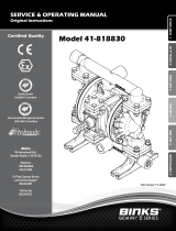
PARTS LIST / 818820, 818821 FLUID SECTION
2
5
914
15
16
19
21
22
29
21
22
FOR THE
AIR MOTOR SECTION
SEE PAGES 7 AND 8
1’’ OUTLET
1’’ INLET
Air Inlet
19
16
26
26
6 3
7
8
3
1
8
6
42
3
7
5
Torque Sequence
Air
Side
Fluid
Side
Cross SectionView
of Diaphragms
1
107
106
105
Figure 2
ASSEMBLY TORQUE REQUIREMENTS
NOTE: DO NOT OVERTIGHTEN FASTENERS.
ALL FASTENERS ARE METRIC.
(14) Bolt, 25 - 30 ft lbs (33.9 - 40.7 Nm), apply Loctite 271 to threads.
(26) Bolts and (29) Nuts, 120 - 140 in. lbs (13.6 - 15.8 Nm).
(105) 40 - 50 in lbs (4.5 - 5.6 Nm).
LUBRICATION / SEALANTS
Apply Key-Lube to all “O” rings, “U” Cups and mating parts.
COLOR CODE
Material Diaphragm
Color
Ball Color
Santoprene® Green N/A
PTFE White White
NOTE: Radius edge of parts (5 and 6) is against diaphragm.

Page 6 of 12 81882X (en)
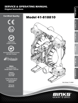
PARTS LIST / 818822, 818823 FLUID SECTION
FOR THE
AIR MOTOR SECTION
SEE PAGES 7 AND 8
Air
Side
Fluid
Side
Cross SectionView of Diaphragms
1
8
6
42
3
7
5
Torque Sequence
Figure 3
15
61
22
29
21
22
19
60
26
26
1’’ OUTLET
1’’INLET
21
19
Air Inlet
107
106
105
2
5
3
1
14
6
3
7
9
8
ASSEMBLY TORQUE REQUIREMENTS
NOTE: DO NOT OVERTIGHTEN FASTENERS.
ALL FASTENERS ARE METRIC.
(14) Bolt, 25 - 30 ft lbs (33.9 - 40.7 Nm), apply Loctite 271 to threads.
(26) Bolts and (29) Nuts, 120 - 140 in. lbs (13.6 - 15.8 Nm).
(105) 40 - 50 in. lbs (4.5 - 5.6 Nm).
LUBRICATION / SEALANTS
Apply Key-Lube to all “O” rings, “U” Cups and mating parts.
Apply Loctite Nickel Anti-seize compound to threads of (26).
COLOR CODE
Material Diaphragm
Color
Ball Color
Santoprene
(backup)
Green N/A
PTFE White White
NOTE: Radius edge of parts (5 and 6) is against diaphragm.

81882X (en) Page 7 of 12
PARTS LIST / 81882X AIR MOTOR SECTION
Indicates parts included in 862003 Air Section Service Kit.
SERVICE KIT NOTE: Service Kit 862003 is a general repair kit for all 1” and larger Bink’s diaphragm pump air motors. It contains extra “O” Rings and other-
parts that may not be needed to service this model.
Item Description (size) Qty Part No. [Mtl]
101 Motor Body (models 6661X0) (1) 873286 [A]
102 “O” Ring (1/16” x 1” OD) (2) [B]
103 Sleeve (1) 873004 [D]
104 Retaining Ring, TruArc (.925” ID) (2) [C]
105 Cap Screw (1/4”-20 x 5/8”) (8) [SS]
106 Lockwasher (1/4”) (8) [SS]
107 Leg (models 818820, 818821) (2) [SS]
107 Plate (models 818822, 818823) (2) [SS]
108 Gasket (with notch) (1) [B/Ny]
109 Piston (1) 873266 [D]
110 “U” Cup (3/16” x 1-3/8” OD) (1) [B]
111 Spool (1) 873001 [A]
112 Washer (1.557” OD) (5) 873267 [Z]
113 “O” Ring (small) (1/8” x 1-1/4” OD) (5) [B]
114 “O” Ring (large) (3/32” x 1-9/16” OD) (6) [B]
Item Description (size) Qty Part No. [Mtl]
115 Spacer (4) 873268 [Z]
116 Spacer (1) 873269 [Z]
117 Gasket (1) [B/Ny]
118 Pilot Rod (1) 873018 [C]
119 “O” Ring (1/8” x 3/4” OD) (4) [U]
120 Spacer (3) 873280 [Z]
121 Sleeve Bushing (2) 873003 [Bz]
122 “O” Ring (3/32” x 9/16” OD) (2) [U]
123 Screw (#8 - 32 x 3/8”) (4) [C]
124 Stud (5/16” - 18 x 1-3/4”) (16) [SS]
128 Pipe Plug (1/8 - 27 N.P.T x 1/4”) (1) [C]
195A Button Head Screw (1/4” - 20 x 1/4”) (2) [SS]
195B Button Head Screw (1/4” - 20 x 3/8”) (1) [SS]
201 Muer (1) 873275 [C]
Key-Lube “O” Ring Lubricant (1)
AIR MOTOR SECTION SERVICE
Service is divided into two parts − 1. Pilot Valve, 2.
Major Valve. GENERAL REASSEMBLY NOTES:
yAir Motor Section Service is continued from Fluid Section
repair.
yInspect and replace old parts with new parts as neces
sary. Look for deep scratches on metallic surfaces, and
nicks or cuts in “O” rings.
yTake precautions to prevent cutting “O” rings upon instal-
lation.
yLubricate “O” rings with Key-Lube grease.
yDo not overtighten fasteners, refer to torque specication
block on view.
yRe-torque fasteners following restart.
PILOT VALVE DISASSEMBLY
1. Remove (104) retaining ring.
2. Remove (123) screws and (122) “O” rings.
3. Remove (118) piston rod, (121) sleeve bushing, (119) “O”
rings and (120) spacers from the (101) motor body.
4. Remove (103) sleeve and (102) “O” rings.
PILOT VALVE REASSEMBLY
1. Replace two (102) “O” rings if worn or damaged and rein-
stall (103) sleeve.
2. Install one of the (121) sleeve bushings, (119) “O” rings,
(120) spacers and the remaining (121) bushing.
3. Carefully push (118) pilot rod into bushings etc. and re-
tain on each end with the two (122) “O” rings, retain with
(123) screws.
4. Replace (104) retaining rings.
MATERIAL CODE
[A] = Aluminum [NY] = Nylon
[B] = Nitrile [SS] = Stainless Steel
[BZ] = Bronze [U] = Polyurethane
[C] = Carbon Steel [Z] = Zinc
[D] = Acetal
MAJOR VALVE DISASSEMBLY
1. Remove (107) plate (or leg depending on model), (108
and 117) gaskets.
2. On the side opposite the air inlet, push on the inner di-
ameter (111) spool. This will force the (109) piston out.
Continue pushing the (111) spool and remove. Check for
scratches and gouges.
3. Reach into the air section (exhaust side) and remove
(116) spacer, (115) spacers, (113) “O” rings, (114) “O” rings,
(112) washers, etc. Check for damaged “O” rings.
MAJOR VALVE REASSEMBLY
1. Replace (112) washer, (114) “O” ring and (113) “O” ring
onto (115) spacer and insert etc.
NOTE: Be careful to orient spacer legs away from
blocking internal ports.
2. Lubricate and carefully insert (111) spool.
3. Install (117) gasket and (107).
4. Lubricate and install (110) packing cup and insert (109)
piston into (air inlet side) cavity, the (110) packing cup
lips should point outward.
5. Install (108) gasket and (107).

Page 8 of 12 81882X (en)
PARTS LIST / 81882X AIR MOTOR SECTION
MAJOR VALVE
See crosssection detail, gure 5.
PILOT VALVE
101
118
112
113
114
115116
119
103
104
123
121
122
120
109
110
IMPORTANT
BE CERTAIN TO ORIENT (115)SPACER LEGS
AWAY FROM BLOCKING INTERNAL PORTS
WHEN REASSEMBLING AIR SECTION.
MAJOR VALVE CROSS SECTION DETAIL
109 110112114113115111 116
Figure 4
Figure 5
124
LUBRICATION/ SEALANTS
Apply Key-Lubegreasetoall “O” rings, “U” Cups and mating parts.
Apply Loctite 271 to threads.
Apply Loctite 262 to threads.
Apply Loctite 572 to threads.
102
128
104
121
123
195A
195A
43
195B
201
108
111
117

81882X (en) Page 9 of 12
TROUBLE SHOOTING
Product discharged from exhaust outlet.
yCheck for diaphragm rupture.
yCheck tightness of diaphragm nut.
Air bubbles in product discharge.
yCheck connections of suction plumbing.
yCheck “O” rings between intake manifold and uid caps.
yCheck tightness of diaphragm nut.
Low output volume, erratic ow, or no ow.
yCheck air supply.
yCheck for plugged outlet hose.
yCheck for kinked (restrictive) outlet material hose.
yCheck for kinked (restrictive) or collapsed inlet material
hose.
yCheck for pump cavitation − suction pipe should be sized
at least as large as the inlet thread diameter of the pump
for proper ow if high viscosity uids are being pumped.
Suction hose must be a non-collapsing type, capable of
pulling a high vacuum.
yCheck all joints on the inlet manifolds and suction con-
nections. These must be air tight.
yInspect the pump for solid objects lodged in the dia-
phragm chamber or the seat area.
DIMENSIONAL DATA - 818820, 818821
(Dimensions shown are for reference only, they are displayed in inchesand millimeters (mm).
8”(203 mm)
12-1/2”
(318 mm)
11-9/16”
(294 mm)
8-9/16”
(217.5 mm)
4”(102 mm)
1-1/4” (32 mm)
7-5/16” (186 mm)
Air Inlet
1/4-18 N.P.T.F. -1
13/32” Slot (10 mm)
6-1/4”(159 mm)
6-1/2”
(165 mm)
Outlet
Inlet
Material Outlet
1 - 11 1/2 NPTF-1 (818820)
1 - 11 BSP (818821)
Material Inlet
1 - 11 1/2 NPTF-1 (818820)
1 - 11 BSP (818821)
Figure 6

Page 10 of 12 81882X (en)
DIMENSIONAL DATA - 818822, 818823
(Dimensions shownare for reference only,theyare displayedininches and millimeters(mm).
8”(203 mm)
12-7/16”
(315 mm)
11-9/16”
(294 mm)
8-9/16”
(217.5 mm)
4”(102 mm)
1-1/4”(32 mm)
Air Inlet
1/4-18 NPTF -1
13/32” Slot (10 mm)
6-1/2”
(165 mm)
Outlet
Inlet
Material Outlet
1 - 11 1/2 NPTF -1 (818822)
1 - 11 BSP (818823)
7-5/16”(186 mm)
6-1/8”(155 mm) Material Inlet
1 - 11 1/2 NPTF -1 (818822)
1 - 11 BSP (818823)
Figure 7

81882X (en) Page 11 of 12

Page 12 of 12 81882X (en)
PN 876007
/