
Model 1043 Metallic Clamped • 6
www.zeeline.com
ns1043mdlCsm-rev0112
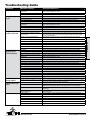
Pump Cycles Once Deadhead (system pressure meets or exceeds air
supply pressure).
Increase the inlet air pressure to the pump. Pump is designed for 1:1 pressure ratio at zero ow.
(Does not apply to high pressure 2:1 units).
Air valve or intermediate gaskets installed incorrectly. Install gaskets with holes properly aligned.
Bent or missing actuator plunger. Remove pilot valve and inspect actuator plungers.
Pump Will Not Operate
/ Cycle
Pump is over lubricated. Set lubricator on lowest possible setting or remove. Units are designed for lube free operation.
Lack of air (line size, PSI, CFM). Check the air line size and length, compressor capacity (HP vs. cfm required).
Check air distribution system. Disassemble and inspect main air distribution valve, pilot valve and pilot valve actuators.
Discharge line is blocked or clogged manifolds. Check for inadvertently closed discharge line valves. Clean discharge manifolds/piping.
Deadhead (system pressure meets or exceeds air
supply pressure).
Increase the inlet air pressure to the pump. Pump is designed for 1:1 pressure ratio at zero ow.
(Does not apply to high pressure 2:1 units).
Blocked air exhaust mufer. Remove mufer screen, clean or de-ice, and re-install.
Pumped uid in air exhaust mufer. Disassemble pump chambers. Inspect for diaphragm rupture or loose diaphragm plate assembly.
Pump chamber is blocked. Disassemble and inspect wetted chambers. Remove or ush any obstructions.
Pump Cycles and Will
Not Prime or No Flow
Cavitation on suction side. Check suction condition (move pump closer to product).
Check valve obstructed. Valve ball(s) not seating
properly or sticking.
Disassemble the wet end of the pump and manually dislodge obstruction in the check valve pocket.
Clean out around valve ball cage and valve seat area. Replace valve ball or valve seat if damaged.
Use heavier valve ball material.
Valve ball(s) missing (pushed into chamber or
manifold).
Worn valve ball or valve seat. Worn ngers in valve ball cage (replace part). Check Chemical
Resistance Guide for compatibility.
Valve ball(s)/seat(s) damaged or attacked by product. Check Chemical Resistance Guide for compatibility.
Check valve and/or seat is worn or needs adjusting. Inspect check valves and seats for wear and proper setting. Replace if necessary.
Suction line is blocked. Remove or ush obstruction. Check and clear all suction screens or strainers.
Excessive suction lift. For lifts exceeding 20’ of liquid, lling the chambers with liquid will prime the pump in most cases.
Suction side air leakage or air in product. Visually inspect all suction-side gaskets and pipe connections.
Pumped uid in air exhaust mufer. Disassemble pump chambers. Inspect for diaphragm rupture or loose diaphragm plate assembly.
Pump Cycles Running
Sluggish/Stalling,
Flow Unsatisfactory
Over lubrication. Set lubricator on lowest possible setting or remove. Units are designed for lube free operation.
Icing. Remove mufer screen, de-ice, and re-install. Install a point of use air drier.
Clogged manifolds. Clean manifolds to allow proper air ow
Deadhead (system pressure meets or exceeds air
supply pressure).
Increase the inlet air pressure to the pump. Pump is designed for 1:1 pressure ratio at zero ow.
(Does not apply to high pressure 2:1 units).
Cavitation on suction side. Check suction (move pump closer to product).
Lack of air (line size, PSI, CFM). Check the air line size, length, compressor capacity.
Excessive suction lift. For lifts exceeding 20’ of liquid, lling the chambers with liquid will prime the pump in most cases.
Air supply pressure or volume exceeds system hd. Decrease inlet air (press. and vol.) to the pump. Pump is cavitating the uid by fast cycling.
Undersized suction line. Meet or exceed pump connections.
Restrictive or undersized air line. Install a larger air line and connection.
Suction side air leakage or air in product. Visually inspect all suction-side gaskets and pipe connections.
Suction line is blocked. Remove or ush obstruction. Check and clear all suction screens or strainers.
Pumped uid in air exhaust mufer. Disassemble pump chambers. Inspect for diaphragm rupture or loose diaphragm plate assembly.
Check valve obstructed. Disassemble the wet end of the pump and manually dislodge obstruction in the check valve pocket.
Check valve and/or seat is worn or needs adjusting. Inspect check valves and seats for wear and proper setting. Replace if necessary.
Entrained air or vapor lock in chamber(s). Purge chambers through tapped chamber vent plugs. Purging the chambers of air can be dangerous.
Product Leaking
Through Exhaust
Diaphragm failure, or diaphragm plates loose. Replace diaphragms, check for damage and ensure diaphragm plates are tight.
Diaphragm stretched around center hole or bolt holes. Check for excessive inlet pressure or air pressure. Consult Chemical Resistance Chart for compatibility
with products, cleaners, temperature limitations and lubrication.
Premature Diaphragm
Failure
Cavitation. Enlarge pipe diameter on suction side of pump.
Excessive ooded suction pressure. Move pump closer to product. Raise pump/place pump on top of tank to reduce inlet pressure.
Install Back pressure device (Tech bulletin 41r). Add accumulation tank or pulsation dampener.
Misapplication (chemical/physical incompatibility). Consult Chemical Resistance Chart for compatibility with products, cleaners, temperature limitations
and lubrication.
Incorrect diaphragm plates or plates on backwards,
installed incorrectly or worn.
Check Operating Manual to check for correct part and installation. Ensure outer plates have not been
worn to a sharp edge.
Unbalanced Cycling Excessive suction lift. For lifts exceeding 20’ of liquid, lling the chambers with liquid will prime the pump in most cases.
Undersized suction line. Meet or exceed pump connections.
Pumped uid in air exhaust mufer. Disassemble pump chambers. Inspect for diaphragm rupture or loose diaphragm plate assembly.
Suction side air leakage or air in product. Visually inspect all suction-side gaskets and pipe connections.
Check valve obstructed. Disassemble the wet end of the pump and manually dislodge obstruction in the check valve pocket.
Check valve and/or seat is worn or needs adjusting. Inspect check valves and seats for wear and proper setting. Replace if necessary.
Entrained air or vapor lock in chamber(s). Purge chambers through tapped chamber vent plugs.
2: INSTAL & OP


 1
1
 2
2
 3
3
 4
4
 5
5
 6
6
 7
7
 8
8
 9
9
 10
10
 11
11


Sandpiper PB1/4, TT4CA Owner's manual
Carlisle Gemini II Pump User manual
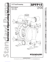 Standard Pump SPFP15NPS Service & Operating Manual
 Binks Gemini II Pumps User manual
 Binks Gemini II Pumps User manual
 Binks Gemini II Pumps User manual
Wilden P2 Engineering Operation & Maintenance Manual


