Page is loading ...

Model 41-818830
Quality System
ISO9001 Certied
Environmental Management System
ISO14001 Certied
9.89
251
10.54
268
11.62
295
4X
.34
9
SUCTION PORT
1/2" NPT (INTERNAL)
1" NPT (EXTERNAL)
DISCHARGE PORT
(OPTIONAL)
1/2" NPT (INTERNAL)
7.19
183
5.50
140
4X
.38
10
6.12
155
8.44
214
EXHAUST PORT
3/8" NPT
1.42
36
5.60
142
9.79
249
1.75
44
1.75
44
5.63
143
8.74
222
DISCHARGE PORT
1/2" NPT (INTERNAL)
1" NPT (EXTERNAL)
SUCTION PORT
(OPTIONAL)
1/2" NPT (INTERNAL)
AIR INLET
1/4" NPT
Binks
195 International Blvd.,
Glendale Heights, IL 60139 USA
Telephone:
1.800.99.BINKS
630.237.5000
Toll Free Customer Service
and Technical Support
800-992-4657
Toll Free Fax
888-246-5732
Part Sheet 77-2997
1: PUMP SPECS2: INSTAL & OP3: EXP VIEW4: AIR END5: WET END6: CERTIFICATES
SERVICE & OPERATING MANUAL
Original Instructions

41-818830sm-rev0812
IMPORTANT
Read the safety warnings and instructions in this manual
before pump installation and start-up. Failure to comply with
the recommendations stated in this manual could damage the
pump and void factory warranty.
When used for toxic or aggressive uids, the pump should
always be ushed clean prior to disassembly.
Airborne particles and loud noise hazards. Wear eye and ear
protection.
Before maintenance or repair, shut off the compressed air line,
bleed the pressure, and disconnect the air line from the pump.
Be certain that approved eye protection and protective clothing
are worn at all times. Failure to follow these recommendations
may result in serious injury or death.
To be fully groundable, the pumps must be ATEX Compliant. Refer to the nomenclature page for ordering information.
Optional Ground Strap (0114-014178) is available for easy ground connection.
To reduce the risk of static electrical sparking, this pump must be grounded. Check the local
electrical code for detailed grounding instruction and the type of equipment required.
Refer to nomenclature page for ordering information.
When the pump is used for materials that tend to settle out
or solidify, the pump should be ushed after each use to
prevent damage. In freezing temperatures the pump should be
completely drained between uses.
Before pump operation, inspect all fasteners for loosening
caused by gasket creep. Retighten loose fasteners to prevent
leakage. Follow recommended torques stated in this manual.
CAUTION
WARNING
Nonmetallic pumps and plastic components are not UV
stabilized. Ultraviolet radiation can damage these parts and
negatively affect material properties. Do not expose to UV light
for extended periods of time.
In the event of diaphragm rupture, pumped material may enter
the air end of the pump, and be discharged into the atmosphere.
If pumping a product that is hazardous or toxic, the air exhaust
must be piped to an appropriate area for safe containment.
This pump is pressurized internally with air pressure during
operation. Make certain that all fasteners are in good condition
and are reinstalled properly during reassembly.
Take action to prevent static sparking. Fire or explosion can
result, especially when handling ammable liquids. The pump,
piping, valves, containers and other miscellaneous equipment
must be properly grounded.
WARNING
Take action to prevent static sparking.
Fire or explosion can result, especially
when handling ammable liquids. The
pump, piping, valves, containers or
other miscellaneous equipment must
be grounded.

41-818830sm-rev0812
•Performance
•Materials
•WarrantyInformation
•DimensionalDrawings
3
•PrincipleofPumpOperation
•RecommendedInstallationGuide
•TroubleshootingGuide
6
•CompositeRepairPartsDrawing
•CompositeRepairPartsList
8
•AirDistributionValveAssembly
•PilotValveAssembly
•IntermediateAssembly
•DiaphragmDrawings
•DiaphragmServicing
•ECDeclarationofConformity-Machinery
•ECDeclarationofConformity-ATEX
•ATEXSummaryofMarkings
1: PUMP SPECS2: INSTAL & OP3: EXP VIEW4: AIR END5: WET END6: CERTIFICATES

41-818830sm-rev0812
1
SUCTION/DISCHARGE PORT SIZE
•1/2"NPT(Internal)or1/2"BSP(Tapered)
•1"NPT(External)or1"BSP(Tapered)
CAPACITY
•0to15gallonsperminute
(0to56litersperminute)
AIR DISTRIBUTION VALVE
•No-lube,no-stalldesign
SOLIDS-HANDLING
•Upto.125in.(3mm)
HEADS UP TO
•125psior289ft.ofwater
(8.6baror86meters)
MAX OPERATING PRESSURE
•125psi(8.6bar)metalliccenter
•100psi(7bar)non-metalliccenter
DISPLACEMENT/STROKE
•.026Gallon/.098liter
SHIPPING WEIGHT
•StainlessSteel21lbs.(10kg)
Material Prole:
Operating
Temperatures:
Max. Min.
Nitrile: Generalpurpose,oil-resistant.Showsgoodsolvent,oil,
waterandhydraulicuidresistance.Shouldnotbeusedwith
highlypolarsolventslikeacetoneandMEK,ozone,chlorinated
hydrocarbons and nitro hydrocarbons.
190°F
88°C
-10°F
-23°C
Santoprene®:Injectionmoldedthermoplasticelastomerwith
nofabriclayer.Longmechanicalexlife.Excellentabrasion
resistance.
275°F
135°C
-40°F
-40°C
CAUTION! Operating temperature limitations are as follows:
Ambient temperature range: -20°Cto+40°C
Process temperature range: -20°Cto+100°Cformodelsratedascategory2equipment
4 6 8 10 12 14 16
20
100
2 (3.5)
4 (7)
80
60
40
20
10 20 30 40 50 60
0
0
1
2
3
4
5
6
7
0
30
20
25
10
15
5
9.1
6
7.6
3
4.5
1.5
6 (10)
8 (13.5)
10 (17)
12 (20)
16 (27)
14 (24)
18 (30)
20 (33.75)
80 PSI (5.44 Bar)
60 PSI (4.08 Bar)
40 PSI (2.72 Bar)
20 PSI (1.36 Bar)
100 PSI (6.8 Bar)
Air Inlet Pressure
CAPACITY
U.S. Gallons per minute
Liters per minute
BAR
SCFM (M /hr)
PSI
HEAD
NPSHR
FEET
METERS
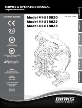
MODEL S05 Metallic Performance Curve
Performance based on the following: elastomer fitted pump, flooded suction, water at ambient conditions.
The use of other materials and varying hydraulic conditions may result in deviations in excess of 5%.
Virgin PTFE:(PFA/TFE)Chemicallyinert,virtuallyimpervious.
VeryfewchemicalsareknowntochemicallyreactwithPTFE;
moltenalkalimetals,turbulentliquidorgaseousuorineand
afewuoro-chemicalssuchaschlorinetriuorideoroxygen
diuoridewhichreadilyliberatefreeuorineatelevated
temperatures.
220°F
104°C
-35°F
-37°C
Maximum and Minimum Temperatures are the limits for which these materials can be operated.
Temperatures coupled with pressure affect the longevity of diaphragm pump components.
Maximum life should not be expected at the extreme limits of the temperature ranges.
Metals:
Stainless Steel: EqualtoorexceedingASTMspecicationA743CF-8Mforcorrosion
resistant iron chromium, iron chromium nickel and nickel based alloy castings for
generalapplications.Commonlyreferredtoas316StainlessSteelinthepumpindustry.
Limited Product Warranty
Binks
®
manufacturing warrants to the original end-use purchaser that no product sold by Binks shall fail under normal use and
service due to a defect in material or workmanship within five years from the date of shipment from Binks factory.
See complete warranty at www.binks.com
1: PUMP SPECS

41-818830sm-rev0812
2
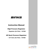
41-818830
DimensionsinInches.(metricdimensionsinbrackets)
Dimensionaltolerance:±1/8"(±3mm)
9.89
251
10.54
268
11.62
295
4X
.34
9
SUCTION PORT
1/2" NPT (INTERNAL)
1" NPT (EXTERNAL)
DISCHARGE PORT
(OPTIONAL)
1/2" NPT (INTERNAL)
7.19
183
5.50
140
4X
.38
10
6.12
155
8.44
214
EXHAUST PORT
3/8" NPT
1.42
36
5.60
142
9.79
249
1.75
44
1.75
44
5.63
143
8.74
222
DISCHARGE PORT
1/2" NPT (INTERNAL)
1" NPT (EXTERNAL)
SUCTION PORT
(OPTIONAL)
1/2" NPT (INTERNAL)
AIR INLET
1/4" NPT
1: PUMP SPECS

41-818830sm-rev0812
3
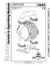
Air-OperatedDoubleDiaphragm(AODD)pumpsarepowered
by compressed air.
The main directional (air) control valve
①
distributes
compressedairtoanairchamber,exertinguniformpressure
over the inner surface of the diaphragm
②
.Atthesametime,
theexhaustingair
③
from behind the opposite diaphragm
isdirectedthroughtheairvalveassembly(s)toanexhaust
port
④
.
Asinnerchamberpressure
(P1)exceedsliquidchamber
pressure
(P2), the rod
⑤
connected diaphragms shift
together creating discharge on one side and suction on the
opposite side. The discharged and primed liquid’s directions
arecontrolledbythecheckvalves(ballorap)
⑥
orientation.
The pump primes as a result of the suction stroke. The
suctionstrokelowersthechamberpressure
(P3) increasing
the chamber volume. This results in a pressure differential
necessary for atmospheric pressure
(P4)topushtheuid
through the suction piping and across the suction side check
valveandintotheouteruidchamber
⑦
.
Suction (side) stroking also initiates the reciprocating
(shifting, stroking or cycling) action of the pump. The suction
diaphragm’s movement is mechanically pulled through its
stroke.Thediaphragm’sinnerplatemakescontactwithan
actuator plunger aligned to shift the pilot signaling valve.
Once actuated, the pilot valve sends a pressure signal to the
opposite end of the main directional air valve, redirecting the
compressed air to the opposite inner chamber.
Air Line
Discharged
Fluid
Discharge
Stroke
Suction
Stroke
Primed
Fluid
2: INSTAL & OP

41-818830sm-rev0812
4
Installation And Start-Up
Locatethepumpasclosetotheproductbeingpumpedaspossible.Keepthesuctionlinelengthandnumberofttingstoaminimum.Donotreducethesuctionline
diameter.
Air Supply
Connectthepumpairinlettoanairsupplywithsufcientcapacityandpressuretoachievedesiredperformance.Apressureregulatingvalveshouldbeinstalledto
insureairsupplypressuredoesnotexceedrecommendedlimits.
Air Valve Lubrication
TheairdistributionsystemisdesignedtooperateWITHOUTlubrication.Thisisthestandardmodeofoperation.Iflubricationisdesired,installanairlinelubricator
settodeliveronedropofSAE10non-detergentoilforevery20SCFM(9.4liters/sec.)ofairthepumpconsumes.ConsultthePerformanceCurvetodetermineair
consumption.
Air Line Moisture
Waterinthecompressedairsupplymaycauseicingorfreezingoftheexhaustair,causingthepumptocycleerraticallyorstopoperating.Waterintheairsupplycan
be reduced by using a point-of-use air dryer.
Air Inlet And Priming
Tostartthepump,slightlyopentheairshut-offvalve.Afterthepumpprimes,theairvalvecanbeopenedtoincreaseairowasdesired.Ifopeningthevalve
increasescyclingrate,butdoesnotincreasetherateofow,cavitationhasoccurred.Thevalveshouldbeclosedslightlytoobtainthemostefcientairowtopump
owratio.
2: INSTAL & OP

41-818830sm-rev0812
5
Symptom: Potential Cause(s): Recommendation(s):
Pump Cycles Once
Deadhead(systempressuremeetsorexceedsair
supply pressure).
Increasetheinletairpressuretothepump.Pumpisdesignedfor1:1pressureratioatzeroow.
(Doesnotapplytohighpressure2:1units).
Airvalveorintermediategasketsinstalledincorrectly. Installgasketswithholesproperlyaligned.
Bentormissingactuatorplunger. Remove pilot valve and inspect actuator plungers.
Pump Will Not Operate
/ Cycle
Pumpisoverlubricated. Setlubricatoronlowestpossiblesettingorremove.Unitsaredesignedforlubefreeoperation.
Lackofair(linesize,PSI,CFM). Checktheairlinesizeandlength,compressorcapacity(HPvs.CFMrequired).
Check air distribution system. Disassembleandinspectmainairdistributionvalve,pilotvalveandpilotvalveactuators.
Dischargelineisblockedorcloggedmanifolds. Checkforinadvertentlycloseddischargelinevalves.Cleandischargemanifolds/piping.
Deadhead(systempressuremeetsorexceedsair
supply pressure).
Increasetheinletairpressuretothepump.Pumpisdesignedfor1:1pressureratioatzeroow.
(Doesnotapplytohighpressure2:1units).
Blockedairexhaustmufer. Removemuferscreen,cleanorde-ice,andre-install.
Pumpeduidinairexhaustmufer. Disassemblepumpchambers.Inspectfordiaphragmruptureorloosediaphragmplateassembly.
Pumpchamberisblocked. Disassembleandinspectwettedchambers.Removeorushanyobstructions.
Pump Cycles and Will
Not Prime or No Flow
Cavitation on suction side. Check suction condition (move pump closer to product).
Checkvalveobstructed.Valveball(s)notseating
properly or sticking.
Disassemblethewetendofthepumpandmanuallydislodgeobstructioninthecheckvalvepocket.
Clean out around valve ball cage and valve seat area. Replace valve ball or valve seat if damaged.
Useheaviervalveballmaterial.
Valveball(s)missing(pushedintochamberor
manifold).
Wornvalveballorvalveseat.Wornngersinvalveballcage(replacepart).CheckChemical
Resistance Guide for compatibility.
Valveball(s)/seat(s)damagedorattackedbyproduct. Check Chemical Resistance Guide for compatibility.
Checkvalveand/orseatiswornorneedsadjusting. Inspectcheckvalvesandseatsforwearandpropersetting.Replaceifnecessary.
Suction line is blocked. Removeorushobstruction.Checkandclearallsuctionscreensorstrainers.
Excessivesuctionlift. Forliftsexceeding20’ofliquid,llingthechamberswithliquidwillprimethepumpinmostcases.
Suction side air leakage or air in product. Visuallyinspectallsuction-sidegasketsandpipeconnections.
Pumpeduidinairexhaustmufer. Disassemblepumpchambers.Inspectfordiaphragmruptureorloosediaphragmplateassembly.
Pump Cycles Running
Sluggish / Stalling,
Flow Unsatisfactory
Over lubrication. Setlubricatoronlowestpossiblesettingorremove.Unitsaredesignedforlubefreeoperation.
Icing. Removemuferscreen,de-ice,andre-install.Installapointofuseairdrier.
Clogged manifolds. Cleanmanifoldstoallowproperairow.
Deadhead(systempressuremeetsorexceedsair
supply pressure).
Increasetheinletairpressuretothepump.Pumpisdesignedfor1:1pressureratioatzeroow.
(Doesnotapplytohighpressure2:1units).
Cavitation on suction side. Check suction (move pump closer to product).
Lackofair(linesize,PSI,CFM). Checktheairlinesize,length,compressorcapacity.
Excessivesuctionlift. Forliftsexceeding20’ofliquid,llingthechamberswithliquidwillprimethepumpinmostcases.
Airsupplypressureorvolumeexceedssystemhd. Decreaseinletair(press.andvol.)tothepump.Pumpiscavitatingtheuidbyfastcycling.
Undersizedsuctionline. Meetorexceedpumpconnections.
Restrictiveorundersizedairline. Installalargerairlineandconnection.
Suction side air leakage or air in product. Visuallyinspectallsuction-sidegasketsandpipeconnections.
Suction line is blocked. Removeorushobstruction.Checkandclearallsuctionscreensorstrainers.
Pumpeduidinairexhaustmufer. Disassemblepumpchambers.Inspectfordiaphragmruptureorloosediaphragmplateassembly.
Check valve obstructed. Disassemblethewetendofthepumpandmanuallydislodgeobstructioninthecheckvalvepocket.
Checkvalveand/orseatiswornorneedsadjusting. Inspectcheckvalvesandseatsforwearandpropersetting.Replaceifnecessary.
Entrainedairorvaporlockinchamber(s). Purgechambersthroughtappedchamberventplugs.Purgingthechambersofaircanbedangerous.
Product Leaking
Through Exhaust
Diaphragmfailure,ordiaphragmplatesloose. Replace diaphragms, check for damage and ensure diaphragm plates are tight.
Diaphragmstretchedaroundcenterholeorboltholes. Checkforexcessiveinletpressureorairpressure.ConsultChemicalResistanceChartforcompatibility
withproducts,cleaners,temperaturelimitationsandlubrication.
Premature Diaphragm
Failure
Cavitation. Enlargepipediameteronsuctionsideofpump.
Excessiveoodedsuctionpressure. Movepumpclosertoproduct.Raisepump/placepumpontopoftanktoreduceinletpressure.
InstallBackpressuredevice(Techbulletin41r).Addaccumulationtankorpulsationdampener.
Misapplication(chemical/physicalincompatibility). ConsultChemicalResistanceChartforcompatibilitywithproducts,cleaners,temperaturelimitations
and lubrication.
Incorrectdiaphragmplatesorplatesonbackwards,
installedincorrectlyorworn.
CheckOperatingManualtocheckforcorrectpartandinstallation.Ensureouterplateshavenotbeen
worntoasharpedge.
Unbalanced Cycling
Excessivesuctionlift. Forliftsexceeding20’ofliquid,llingthechamberswithliquidwillprimethepumpinmostcases.
Undersizedsuctionline. Meetorexceedpumpconnections.
Pumpeduidinairexhaustmufer. Disassemblepumpchambers.Inspectfordiaphragmruptureorloosediaphragmplateassembly.
Suction side air leakage or air in product. Visuallyinspectallsuction-sidegasketsandpipeconnections.
Check valve obstructed. Disassemblethewetendofthepumpandmanuallydislodgeobstructioninthecheckvalvepocket.
Checkvalveand/orseatiswornorneedsadjusting. Inspectcheckvalvesandseatsforwearandpropersetting.Replaceifnecessary.
Entrainedairorvaporlockinchamber(s). Purgechambersthroughtappedchamberventplugs.
2: INSTAL & OP

41-818830sm-rev0812
6
41-718850 Air Motor Repair Kit
Bumpers,Bushings,Gaskets,O-rings,RetainingRings,andSeals.
41-718851 Diaphragm Kit
SantopreneBackupDiaphragms,PTFEOverlayDiaphragms,PTFE
ManifoldO-rings,FEP-EncapsulatedFKMO-ringsformetalcheck
valve seats.
41-718852 Ball and Seat Kit
316StainlessSteelCheckBalls,316StainlessSteelCheckValve
Seats,FEP-EncapsulatedFKMO-ringsforthemetalcheck
valve seats.
Service Kits
8
20
3
22
13
21
1
26
12
10
37
35
32
28
7
33
34
6
31
4
10
24
37
9
37
9
10
38
38
15
16
30
9
Alum Center
Torque:
70 in/lbs
Torque:
120 in/lbs
14
37
27
37
2
29
36
29
2
29
29
36
10
Alum Center
25
10
10
37
9
3: EXP VIEW

41-818830sm-rev0812
7
1 AirValveAssembly 1
2 Ball,Check 4
3 PilotValveAssembly 1
4 Bracket,Intermediate 1
6 Bumper,Diaphragm 2
7 Bushing,Plunger 2
8 Cap,AirInlet 1
9 Capscrew,Hex5/16-18X1.00 12
10 Capscrew,Hex5/16-18x1.25(SS) 24
12 Capscrew,Flanged1/4-20x75 4
13 Capscrew,Flanged1/4-20x1.50 4
14 Chamber,Outer 2
15 Diaphragm 2
16 Diaphragm,Overlay 2
20 Gasket,AirInlet 1
21 Gasket,AirValve 1
22 Gasket,PilotValve 1
24 Manifold,Suction 1
25 Manifold,Discharge 1
26 MetalMufer 1
27 Nut,Hex5/16-18(StainlessSteel) 8
28 O-Ring 2
29 O-Ring(metallicseatsonly) 8
30 Plate,OuterDiaphragm 2
31 Plate,InnerDiaphragm 2
32 Plunger,Actuator 2
33 Ring,Retainer 2
34 Rod,Diaphragm 1
35 Seal,U-CupShaft 2
36 Seat,CheckValve(item29required) 4
37 5/16LockWasher(StainlessSteel) 32
38 1/2NPTPipePlug 2
Item Description Qty
=Itemscontainedwithin
41-718850 AirMotorRepairKits
=Itemscontainedwithin
41-718853DiaphragmKits
=Itemscontainedwithin
41-718854 BallandSeatKits
3: EXP VIEW

41-818830sm-rev0812
8
1-E
1-D
1-C
1-F
1-F
1-A
1-B
1-C
1-F
1-F
1-D
1-E
Main Air Valve Assembly Parts List
Item Description Qty
1 Valve Assembly 1
1-A SleeveandSpoolSet1
1-B ValveBody 1
1-C Bumper 2
1-D EndCap 2
1-E HexFlangeCapscrew1/4-20x.75 8
1-F O-Ring 4
Air Distribution Valve Servicing
Seerepairpartsdrawing,removescrews.
Step 1:Removehexcapscrews(1-E).
Step 2: Removeendcap(1-D).
Step 3: Removespoolpartof(1-A)(caution:donotscratch).
Step 4: Presssleeve(1-A)frombody(1-B).
Step 5:Inspectbumpers(1-C)ando-rings(1-F).
Step 6:LightlylubricateO-Rings(1-F)onsleeve(1-A).
Step 7: Presssleeve(1-A)intobody(1-B).
Step 8: Reassembleinreverseorder,startingwithstep3.
Note: Sleeveandspool(1-A)setismatchgroundtoaspeciedclearance
sleeveandspools(1-A)cannotbeinterchanged.
IMPORTANT
Read these instructions completely, before installation
and start-up. It is the responsibility of the purchaser
to retain this manual for reference. Failure to comply
with the recommendations stated in this manual will
damage the pump, and void factory warranty.
=Itemscontainedwithin
41-718850 AirMotorRepairKits
4: AIR END

41-818830sm-rev0812
9
Pilot Valve Servicing
WithPilotValveremovedfrompump.
Step 1:Removesnapring(3-F).
Step 2:Removesleeve(3-B),inspectO-Rings(3-C),
replace if required.
Step 3: Removespool(3-D)fromsleeve(3-B),
inspectO-Rings(3E),replaceifrequired.
Step 4: LightlylubricateO-Rings(3-C)and(3-E).
Reassemble in reverse order.
Pilot Valve Assembly Parts List
For Models Equipped with Aluminum Midsections
Item Description Qty
3 PilotValveAssembly 1
3-A ValveBody 1
3-B Sleeve(WithO-Rings) 1
3-C O-Ring(Sleeve) 6
3-D Spool(WithO-Rings) 1
3-E O-Ring(Spool) 3
3-F RetainingRing 1
=Itemscontainedwithin
41-718850 AirMotorRepairKits
4: AIR END

41-818830sm-rev0812
10
7
26
21
4
21
7
26
25
25
35
IMPORTANT
When the pumped product source is at a higher
level than the pump (ooded suction condition),
pipe the exhaust higher than the product source
to prevent siphoning spills. In the event of a
diaphragm failure a complete rebuild of the
center section is recommended.
Intermediate Repair Parts List
Item Description
Qty
4 Bracket,Intermediate 1
7 Bushing,Plunger 2
28 O-Ring 2
32 Plunger,Actuator 2
33 Ring,Retaining* 2
35 Seal,DiaphragmRod 2
*Note:Itisrecommendedthatwhenplungercomponentsareserviced,
newretainingringsbeinstalled.
Intermediate Assembly Drawing
Step 1: Removeplunger,actuator(25)fromcenterof
intermediate pilot valve cavity.
Step 2: RemoveRing,Retaining(26),discard.
Step 3: Removebushing,plunger(7),inspectforwear
andreplaceifnecessarywithgenuineparts.
Step 4: RemoveO-Ring(21),inspectforwearand
replaceifnecessarywithgenuineparts.
Step 5: LightlylubricateO-Ring(21)andinsertinto
intermediate.
Step 6: UtilizinganewRing,Retaining(26)reassemble
in reverse order
Step 7: RemoveSeal,DiaphragmRod(35).
Step 8: Cleansealarea,lightlylubricateandinstallnewSeal,
DiaphragmRod(28).
=Itemscontainedwithin
41-718850 AirMotorRepairKits
4: AIR END

41-818830sm-rev0812
11
30
16
11
37
14
15
11
37
14
11
27
37
34
6
31
30
16
17
11
Diaphragm Orientation
Installdiaphragmandspacer
asshownabove.
Torque:
120 in/lbs
5: WET END

41-818830sm-rev0812
12
Step 1: With manifoldsandouter chambers
removed, remove diaphragm assemblies from
diaphragm rod. DO NOTuseapipewrenchorsimilar
tooltoremoveassemblyfromrod.Flawsintherod
surfacemaydamagebearingsandseal.Softjaws
in a vise are recommended to prevent diaphragm
rod damage.
Step 1.A: NOTE: Notallinnerdiaphragmplates
arethreaded.Some modelsutilizea throughhole
intheinnerdiaphragmplate.Ifrequiredtoseparate
diaphragm assembly, place assembly in a vise,
gripping onthe exterior castdiameterof the inner
plate.Turntheouterplateclockwisetoseparatethe
assembly.
Alwaysinspectdiaphragmsfor wear cracksor
chemicalattack. Inspectinner andouterplatesfor
deformities,rustscaleandwear.Inspectintermediate
bearingsforelongationandwear.Inspectdiaphragm
rodforwearormarks.
Clean or repair if appropriate. Replace as required.
Step 2: Reassembly:Therearetwodifferenttypes
ofdiaphragmplateassembliesutilizedthroughoutthe
Sandpiperproductline:Outerplatewithathreaded
stud, diaphragm, and a threaded inner plate.
Outerplatewith athreadedstud, diaphragm,and
aninnerplate withthroughhole. Securethreaded
innerplateinavise.Ensurethattheplatesarebeing
installedwiththeouterradiusagainstthediaphragm.
Step 3:Lightlylubricate,withacompatiblematerial,
the inner faces of both outer and inner diaphragm plates
whenusingonnonOverlaydiaphragms(ForEPDM
waterisrecommended).Nolubricationisrequired.
Step 4: Pushthethreaded outer diaphragm
plate through the center hole of the diaphragm.
Note: Most diaphragms areinstalled with the
naturalbulgeout towards thefluidside. S05,
S07, and S10 non–metallic units are installed
withthenatural bulge intowards the airside.
Step 5: Thread or place, outer plate stud into
the inner plate. For threaded inner plates, use a
torquewrenchto tighten theassemblytogether.
Torquevaluesarecalledoutontheexplodedview.
Repeat procedure for second side assembly.
Allowaminimum of 15minutesto elapse after
torquing, then re-torque the assembly to compensate
forstressrelaxation in theclampedassembly.
Step 6: Thread one assembly onto the diaphragm
rodwith sealingwasher (whenused)andbumper.
Step 7: Install diaphragm rod assembly
into pump and secure by installing the outer
chamberinplace andtighteningthe capscrews.
Step 8: On opposite side of pump, thread the
remainingassemblyontothediaphragmrod.Usinga
torquewrench,tightentheassemblytothediaphragm
rod.Aligndiaphragmthroughboltholes,alwaysgoing
forwardpasttherecommendedtorque.Torquevalues
arecalledoutontheexplodedview.NEVER reverse
to align holes, if alignment cannot be achieved
withoutdamageto diaphragm, loosencomplete
assemblies, rotate diaphragm and reassemble as
described above.
IMPORTANT
Read these instructions completely,
before installation and start-up.
It is the responsibility of the
purchaser to retain this manual for
reference. Failure to comply with
the recommendations stated in this
manual will damage the pump, and
void factory warranty.
5: WET END

Declaration of Conformity
Signature of authorized person
Date of issue
Printed name of authorized person
Revision Level: E
Title
Engineering Manager
Charles W. McCulloch
June 8, 2012
June 8, 2012
Date of revision
BINKS, 195 International Blvd, Glendale Heights, IL 60139
Certifies that BINKS models: 41-818810, 41-818820, 41-818822, 41-818830,
41-818823, 41-818836 Air-Operated Double Diaphragm Pump comply with the
European Community Directive 2006/42/EC on Machinery, according to Annex VIII.
This product has used Harmonized Standard EN809:1998+A1:2009, Pumps and
Pump Units for Liquids - Common Safety Requirements, to verify conformance.
6: CERTIFICATES

In accordance with ATEX Directive 94/9/EC,
Equipment intended for use in potentially explosive environments.
AODD Pumps
For Type Examination Designations, see page 2 (back)
Manufacturer:
BINKS
195 International Blvd
Glendale Heights, IL 60139
Applicable Standard:
EN13463-1: 2001,
EN13463-5: 2003
KEMA Quality B.V.
Utrechtseweg 310
6812 AR Arnhem, The Netherlands
EC Declaration of Conformity
DATE/APPROVAL/TITLE:
Charles W. McCulloch, Engineering ManagerJune 11, 2012
6: CERTIFICATES

EC Declaration of Conformity
ATEX Summary of Markings
Type Marking Listed In
Non-Conductive
Fluids
Type Certificate No. Pumps: KEMA 09ATEX0072 X
BINKS Models:
41-818810
41-818820
41-818822
41-818830
41-818831
41-818836
II 2 G c T5
II 3/2 G c T5
II 2 D c T100
o
C
KEMA 09ATEX0072 X
KEMA 09ATEX0072 X
KEMA 09ATEX0072 X
No
Yes
Yes
KEMA 09ATEX0072 X
CE
6: CERTIFICATES
/