Page is loading ...

BALLAST/BULB TO LED
FIELD CONVERSION GUIDE
(FOR MID/HIGH TOPPER SIGNAGE)
CORPORATE HEADQUARTERS: RMA (RETURN MATERIAL AUTHORIZATION)
RETURN ADDRESS:
522 E. Railroad Street 21405 Avenue “B”
Long Beach, MS 39560 Long Beach, MS 39560
Phone: (228) 868-1317
Fax: (228) 868-0437
VERSION 2.0
TDN 07103-00146B 05/2007
COPYRIGHT NOTICE
© 2006-2007 Delaware Capital Formation, Inc. All Rights Reserved. Triton Systems of Delaware, Inc. is an
operating company of Dover Electronics, Inc., a subsidiary of Dover Corporation (NYSE-DOV). DOVER,
the DOVER logo and the Dover family of marks and TRITON, the TRITON logo and the Triton family of
marks are registered trademarks of Delaware Capital Formation, Inc., a wholly owned subsidiary of Dover
Corporation.

2
BALLAST/BULB TO LED CONVERSION (MID/HIGH TOPPERS)
INTRODUCTION
This guide covers the steps for removal of the ballast/flourescent bulb assembly and installation of the
LED light bar assembly(s) and cable connectivity. These procedures include a list of tools and hardware
required for the replacement as well as the steps involved.
! MIDTOPPER LED FIELD CONVERSION KIT (P/N 06200-08109). Models 8100/9100/97XX/
RL5000 (X-Scale).
! MIDTOPPER LED FIELD CONVERSION KIT (P/N 06200-08119). Model RL5000
XP
only.
! HIGHTOPPER LED FIELD CONVERSION KIT (P/N 06200-08110). Models 97XX/RL5000 X-Scale.
! HIGHTOPPER LED FIELD CONVERSION KIT (P/N 06200-08120). Model RL5000
XP
only.
** Attention **
Flourescent bulb contains mercury. Dispose of according
to local, state, or federal laws. For more information (US),
go to www.lamprecycle.org.
IMPORTANT NOTICE
Triton Systems has discontinued offering a ballast/bulb (AC-powered) light
assembly for topper signage (mid/high) and light panels. This affects models
8100, 9100, 97XX, RL5000 (X-Scale/XP), and FT5000 (X-Scale) units. LED-lit
(DC-powered) light assemblies will be the replacement option.
Note: Limited ballast/bulb parts may be available for field replaceable
parts and repair until current inventory is depleted.

3
BALLAST/BULB TO LED CONVERSION (MID/HIGH TOPPERS)
SCOPE
This Midtopper conversion procedure applies to all service personnel involved in the process of maintaining
or converting Triton ATMs.
REQUIRED PARTS AND TOOLS
BALLAST/BULB LIGHT A SSEMBLY
LED LIGHT PANEL
DERIUQERSLOOT
)citengaM(revirdwercSspillihP2#
STIKNOITALLATSNIDELREPPOTDIM
90180-00260N/P
0005LR(91180-00260N/P
PX
)ylno
DEILPPUSSTRAP
REBMUNTRAP NOITPIRCSED YTITNAUQ
88100-00190DEL,eludoMraBthgiL1
76900-11030raBthgiLDEL,tekcarB1
60000-05020panS,teviR6
.rehtegotdelbmessayrotca
feblliwevobadetsilstrap)3(eerhtehT:etoN
1
09300-02190
)xelomnip-8(sDEL,elbaCrewoP1
2
33600-02190
(sDEL,elbaCrewoPxelomnip-2) 1
3
62800-02190
elbaC
,
rewoPrettilpS
1
05100-00250
DCnoitallatsnIDEL
)launamnoitallatsnIDEL64100-30170sedulcnI(
1
1
90180-00260tiknidedulcnI
2
91180-00260tiknidedulcnI
3
resnepsidhceminiMroMDThtiwsMTA0019ledoMrofderiuqeR

4
BALLAST/BULB TO LED CONVERSION (MID/HIGH TOPPERS)
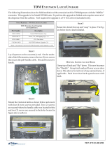
3. Carefully flip the entire assembly over, so that the front side is up. Lift the front of the topper
assembly away from the rear half. It may be necessary to tilt the panel to clear the four mounting
studs. Set the front panel aside.
4. Rear panel. Remove the four (4) screws that
hold the ballast/bulb assemblies. Discard these
assemblies accordingly. Set rear panel aside.
Note: These procedures are completed with the terminal AC power OFF.
For RL5000 units. If terminal is ON, enter MANAGEMENT FUNCTIONS > SYSTEM PARAMETERS > SHUT DOWN
TERMINAL. When prompted, turn power OFF on the units power supply.
MIDTOPPER LED CONVERSION PROCEDURE
1. Unlock and open the cabinet control panel. Using a 3/8" nut driver, remove the nuts that secure the
topper assembly. Remove the Midtopper assembly and place on a flat surface, rear side up, as shown
in Figure below..
""
""
" REMOVING BALLAST/BULB A SSEMBLIES:
2. Remove the four (4) screws that hold the front and rear panels of the assembly together. Retain the
screws.

5
BALLAST/BULB TO LED CONVERSION (MID/HIGH TOPPERS)
!!
!!
! INSTALL LED LIGHT BAR/BRACKET/CABLE:
5. Front panel. Remove the two (2) screws shown and remove
the lower sign plastic standoff. Retain the screws. Discard
the plastic standoff.
7. Mount the LED light bar assembly (factory assembled) as shown and secure with the two (2) screws
removed in Step 5 above.
6. Connect the LED power cable shown below to either <J1>
or <J5> on the LED light bar assembly (pre-assembled).
Note: Either jack will work depending which one is
away from the bracket flange.
8. Reinstall the topper rear panel. Flip the chassis over and attach the two halves using the four (4)
screws removed in Step 2.
** IMPORTANT **
Before installing the LED light bar
assembly, verify the light bar circuit board
is mounted UNDER the bracket flanges as
shown above.
Flange
Flange
Flange
9. Reinstall the Midtopper to the cabinet.

6
BALLAST/BULB TO LED CONVERSION (MID/HIGH TOPPERS)
DC CONNECTIONS (LED-LIT TOPPER)
Plug the LED power cord (8-pin molex connector) from the topper into any available DC output connector
on the power supply (*see Notes) as shown in Figures 1 -4.
1
Note: The dispensing mechanism uses the largest molex connection on the power supply.
2
Note: Model RL5000XP only. The power cord is a 2-pin molex connector. This 2-pin connects to the
GPIO board assembly. Figure 5 show the GPIO connection point.
3
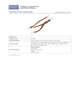
Note: Model 9100 w/TDM or Minimech dispensers. The LED power cord requires a power splitter
adapter (included). Figures 6 through 8 show the connection points.
Figure 1. Model 9100 (w/SDD)
Figure 2. Model 97XX
Figure 3. Model RL5000 (X-Scale)
Figure 4. Model 8100

7
BALLAST/BULB TO LED CONVERSION (MID/HIGH TOPPERS)
GPIO assy
Figure 5. Model RL5000 (XP)
3
Note: 9100 w/TDM or Minimech - Locate the Power splitter adapter included in kit (Figure below). The
cables connectors are marked. Disconnect the Main boards power input (Figure 6) and connect to one
leg of the extension cable. Connect the toppers DC power cable to the other leg (Figure 7). Reconnect
this power cable assembly back to the main board. Figure 8 shows the power assembly diagram.
Power splitter adapter

8
BALLAST/BULB TO LED CONVERSION (MID/HIGH TOPPERS)
Figure 6. Main board power disconnected.
Figure 7. Power splitter cable with topper and main
board power cables connected.
LED Topper
Power Supply
Main Board
Figure 8. Power splitter cable configuration.
10. Turn the power supply to ON (I). The topper sign should light up. Close and lock the control panel.

9
BALLAST/BULB TO LED CONVERSION (MID/HIGH TOPPERS)
SCOPE
This Hightopper conversion procedure applies to all service personnel involved in the process of
maintaining or converting Triton ATMs.
REQUIRED PARTS AND TOOLS
DERIUQERSLOOT
)citengaM(revirdwercSspillihP2#
srettuClanogaiD
TIKNOITALLATSNIDELREPPOTHGIH
01180-00260N/P
0005LR(02180-00260N/P
PX
)ylno
DEILPPUSSTRAP
REBMUNTRAP NOITPIRCSED YTITNAUQ
88100-00190DEL,eludoMraBthgiL1
15010-11030)thgiR(,raBthgiLDEL,tekcarBpoT1
25010-11030)tfeL(,raBthgiLDEL,tekc
arBpoT1
60000-05020panS,teviR4
ehT:etoN
ruof
ehtrofrehtegotdelbmessayrotcafeblliwevobadetsilstrap)4(
poT.ylbmessatekcarbDEL
88100-00190DEL,eludoMraBth
giL1
60000-05020
,teviRanSp
6
05000-45020wercS4
21400-02190
lbaC
,e
repmuJ
,
DELPlenas
1
3
74010-11030
thgiR,egniH
1
3
84010-11030
feL,egniH
t
1
1
11400-02190
rewoP
)xelomnip-8(sDEL,elbaC
1
2
33600-02190
)xelomnip-2(sDEL,elbaCrewoP1
05100-00250
DCnoitallatsnIDEL
)launamnoitallatsnIDEL64100-30170se
dulcnI(
1
1
01180-00260tiknidedulcnI
2
02180-00260tiknidedulcnI
3
elytsredlorofderiuqeR
hgih
sreppot

10
BALLAST/BULB TO LED CONVERSION (MID/HIGH TOPPERS)
Note: These procedures are completed with the terminal AC power OFF.
For RL5000 units. If terminal is ON, enter MANAGEMENT FUNCTIONS > SYSTEM PARAMETERS > SHUT DOWN
TERMINAL. When prompted, turn power OFF on the units power supply.
HIGHTOPPER LED CONVERSION PROCEDURE
1. Unlock and open the cabinet control panel. Unplug the Hightopper power cable from the power
supply.
2. Using a phillips screwdriver, loosen or remove the screws that secure the Hightopper legs to the
mounting brackets. Remove the Hightopper assembly and place on a flat surface, front panel up, as
shown in Figure below.
""
""
" REMOVING HIGHTOPPER/PANEL ASSEMBLIES:
3. Unlock, open and remove the front cover panel by lifting free of assembly.
""
""
" REMOVING BALLAST/BULB A SSEMBLY:
4. Using a phillips screwdriver, remove the two (2) screws on the Left leg bracket cover. Remove the
cover and retain the screws. Feed the AC power cable out of the leg bracket until it’s free of the
assembly. Note: Cut any Ty wraps that are securing the cable to the leg assembly.
Reinstall the cover and secure with screws.

11
BALLAST/BULB TO LED CONVERSION (MID/HIGH TOPPERS)
5. Note: The ballast/bulb assemblies are secured to a back plate. This step will remove the plate
(with ballast/bulb still attached). The plate is not required for the conversion procedures.
Remove the bulb. Using a phillips screwdriver, remove the four (4) screws shown. Next, remove the
plate (with ballast/bulb/power cable assembles) from the hightopper assembly. Figure below shows
the hightopper assembly with ballast/bulb assemblies removed.
Note: There are two (2) LED light bar assemblies to install. The first step is for the Top (closest to lock
latch) LED assembly..
""
""
" INSTALL LED LIGHT BAR/BRACKET A SSEMBLIES:
6. Mount the LED light bar assembly (factory assembled) as shown and secure with the four (4) screws

12
BALLAST/BULB TO LED CONVERSION (MID/HIGH TOPPERS)
7. Lower LED - Install the other LED light bar assembly to the existing brackets (or kit brackets if
required) and secure with four (4) plastic rivets. Light bar mounts towards inside of bracket and
rivets inserted on same side. The figures below and on the next page show the brackets, direction of
the light bar, and both LED light bars installed.
Note: The direction of the light bar assembly (Triton logo up/down) is not relevant. The power
connectors <J1> and <J5> are electrically the same.
Hinge brackets required.
* NOTE *
Before installing the lower LED light bar, ensure the required hinge brack-
ets are correct. If you have a topper with hinge brackets that look like the
ones pictured below, you must first replace these with the brackets in-
cluded in the kit.

13
BALLAST/BULB TO LED CONVERSION (MID/HIGH TOPPERS)
LED light bars installed.
Lower LED installed.
""
""
" INSTALL/ROUTE LED POWER CABLES:
Note: The power connectors <J1> and <J5> are electrically the same.
Example of cable connections.
LED Light Bar
J1
J5
LED Light Bar
J1
J5
Power Supply
GPIO
Board
8. LED Panels Jumper Cable - Locate the jumper cable included in kit (P/N 09120-00412). Connect one
end to the Top LED light bar, either <J1> or <J5> (whichever is closest to white panel) and route
cable down to the Lower LED light bar. Connect this end to either <J1> or <J5> (whichever is
closest to white panel).
Jumper cable connected and routed.

14
BALLAST/BULB TO LED CONVERSION (MID/HIGH TOPPERS)
10. Route the cable down through the Right leg assembly. Reinstall the front cover panel.
11. Install the converted Hightopper assembly to the ATM and secure. Connect the 8-pin or 2-pin molex
connector end to the applicable power source. See pages 6 and 7 for locations. Secure cable to
topper leg with Ty wraps included
9. LED Power Cable - Locate the power cable included in kit (P/N 09120-00411 (8-pin molex end) or
(P/N 09120-00633 - 2-pin molex ends). Connect one end of the cable to either <J1> or <J5> on the
Lower LED light bar (whichever is available).
/