HP Smart Array (RAID) Host Bus Adapters Installation guide
- Category
- System management software
- Type
- Installation guide

AM311A Smart Array P411/256 Controller
for HP Integrity Servers Installation Guide
Abstract
This guide includes procedures to install, update, and configure HP Smart Array P411/256 controllers on HP Integrity servers.
HP Part Number: AM311-9000B
Published: September 2011
Edition: 2

© Copyright 2011 Hewlett-Packard Development Company, L.P.
Legal notice
The information contained herein is subject to change without notice. The only warranties for HP products and services are set forth in the express
warranty statements accompanying such products and services. Nothing herein should be construed as constituting an additional warranty. HP shall
not be liable for technical or editorial errors or omissions contained herein.
Confidential computer software. Valid license from HP required for possession, use or copying. Consistent with FAR 12.211 and 12.212, Commercial
Computer Software, Computer Software Documentation, and Technical Data for Commercial Items are licensed to the U.S. Government under
vendor's standard commercial license.
Trademark acknowledgements
Intel® is a trademark of Intel Corporation in the U.S. and other countries. Itanium® is a trademark of Intel Corporation in the U.S. and other countries.
Microsoft® is a U.S. registered trademark of Microsoft Corporation. Windows® is a U.S. registered trademark of Microsoft Corporation

Contents
1 Controller overview.....................................................................................5
2 Windows installation..................................................................................6
Installation overview..................................................................................................................6
3 HP-UX installation.......................................................................................8
Installation overview..................................................................................................................8
HP-UX installation prerequisites...................................................................................................9
Downloading software..............................................................................................................9
Installing software...................................................................................................................10
Verifying the installation..........................................................................................................10
4 Installing, verifying, and configuring the controller........................................11
Installing the controller hardware..............................................................................................11
Connecting and verifying external storage devices......................................................................11
Connecting external storage devices.....................................................................................11
Verifying external disk enclosure connections.........................................................................12
Verifying tape device connections........................................................................................13
Verifying and updating controller firmware offline.......................................................................14
Verifying the controller firmware...........................................................................................14
Downloading the firmware update.......................................................................................15
Updating the controller firmware..........................................................................................16
Verifying the firmware update.........................................................................................17
HELP................................................................................................................................18
Error messages..................................................................................................................19
Determining and setting the controller mode...............................................................................19
GET_MODE......................................................................................................................19
SET_MODE.......................................................................................................................20
Verifying and updating enclosure firmware offline.......................................................................21
Verifying the enclosure firmware...........................................................................................21
Downloading the enclosure firmware....................................................................................22
Updating the enclosure firmware..........................................................................................23
Verifying the firmware update.........................................................................................24
HELP ...............................................................................................................................24
Updating tape device firmware.................................................................................................25
Using Option ROM Configuration for Arrays (ORCA)..................................................................25
Accessing ORCA...............................................................................................................25
Creating a logical drive......................................................................................................28
Deleting a logical drive......................................................................................................28
5 Troubleshooting........................................................................................31
Smart Array P411 controller board runtime LEDs..........................................................................31
POST messages......................................................................................................................32
6 Support and other resources......................................................................33
About this document...............................................................................................................33
Intended audience..................................................................................................................33
Typographic conventions.........................................................................................................33
Related information.................................................................................................................33
HP encourages your comments.................................................................................................33
A Electrostatic discharge..............................................................................35
Handling parts.......................................................................................................................35
Grounding.............................................................................................................................35
Contents 3


1 Controller overview
This chapter provides an overview of the physical characteristics of the HP Smart Array P411/256
Controller.
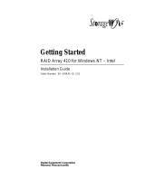
Figure 1 HP AM311A Smart Array 411 controller components
1
3
2
4
431
Connector for SAS miniports
1 and 2, each 4x wide.
(On rear of cache) Connector
for the cable to an optional
Status LEDs (runtime LEDs).
To interpret the illumination
cache battery that upgrades
the cache to BBWC.
pattern of these LEDs, see
Table 2 (page 31).
2
Cache module (also known
as array accelerator).
5

2 Windows installation
This chapter describes installing Smart Array P411/256 Controllers on HP Integrity servers running
Microsoft Windows.
Installation overview
WARNING! The HP AM311A Smart Array P411 controller does not support SATA disks in its
initial release with adapter firmware version 3.30. SATA support will be added in a future firmware
update.
For the latest information on recommended adapter firmware, see the HP Smart Array RAID
Controllers Support Matrix at:
http://www.hp.com/go/smart-array-raid-docs.
NOTE: PCI card hot-plug addition and deletion operations are not supported on this controller;
you must install it offline.
To install your Smart Array P411/256 controller, follow these steps:
1. Confirm that the server model, storage enclosure, and operating system are supported with
the Smart Array P411/256 controller. Also, determine the required versions for the system
firmware, adapter firmware, UEFI driver, and enclosure firmware.
• For information about supported servers, disk enclosures, and firmware versions, see the
HP Smart Array RAID Controllers Support Matrix at:
http://www.hp.com/go/smart-array-raid-docs.
• For information about supported tape devices, see the following documents:
◦ The Smart Array P411 QuickSpecs, at:
http://h18004.www1.hp.com/products/quickspecs/13765_div/13765_div.html
◦ The HP StorageWorks Single Point of Connectivity Knowledge (SPOCK) website, at:
http://www.hp.com/storage/spock
An HP Passport account is required to access the SPOCK website.
2. Update the system firmware on the server, if necessary. For more information, see the
documentation for your server.
3. Back up all server data.
4. Power off the server.
5. Power off any peripheral devices.
6. Unplug the AC power cord from the server.
7. Disconnect any peripheral devices.
8. Install the controller hardware. See “Installing the controller hardware” (page 11).
9. Connect storage devices to the controller. See “Connecting and verifying external storage
devices” (page 11).
NOTE: If you are connecting both disk and tape devices, do not combine them on the same
SAS connector. Connect disk devices to one connector, and tape devices to the other.
10. Reconnect the peripheral devices and the AC power supply to the server.
11. Power on the peripheral devices and storage devices.
12. Power on the server.
6 Windows installation

13. Update the controller firmware, if necessary. See “Verifying and updating controller firmware
offline” (page 14).
14. Determine whether the controller is in RAID mode; if not, then set it to RAID mode. See
“Determining and setting the controller mode” (page 19).
15. Update the storage enclosure firmware, if necessary. See “Verifying and updating enclosure
firmware offline” (page 21).
16. (Optional) Set the Smart Array P411/256 as the boot controller. For more information about
setting the boot controller, see the server documentation.
17. Configure an array. See “Creating a logical drive” (page 28).
Installation overview 7

3 HP-UX installation
This chapter describes installing Smart Array P411/256 Controllers on HP Integrity servers running
HP-UX.
Installation overview
WARNING! The HP AM311A Smart Array P411 controller does not support SATA disks in its
initial release with adapter firmware version 3.30. SATA support will be added in a future firmware
update.
For the latest information on recommended adapter firmware, see the HP Smart Array RAID
Controllers Support Matrix at:
http://www.hp.com/go/smart-array-raid-docs.
NOTE: HP-UX Online Addition, Removal and Deletion (OL*) operations are not supported on
this controller; you must install it offline.
To install your Smart Array Series Controller, follow these steps:
1. Plan your storage device configurations.
• For more information on supported RAID levels, see the HP Smart Array SAS Controllers
for Integrity Servers Support Guide at:
http://www.hp.com/go/smart-array-raid-docs
• For information about supported servers and disk enclosures, see the HP Smart Array
RAID Controllers Support Matrix at:
http://www.hp.com/go/smart-array-raid-docs.
• For information about supported tape devices, see the following documents:
◦ The Smart Array P411 QuickSpecs, at:
http://h18004.www1.hp.com/products/quickspecs/13765_div/13765_div.html
◦ The HP StorageWorks Single Point of Connectivity Knowledge (SPOCK) website, at:
http://www.hp.com/storage/spock
An HP Passport account is required to access the SPOCK website.
2. Update the system firmware on the server, if necessary. For more information, see the
documentation for your server.
3. Check the installation prerequisites. See “HP-UX installation prerequisites” (page 9).
4. Install the software. See “Downloading software” (page 9) and “Installing software” (page 10).
5. Back up all server data.
6. Power off the server.
7. Power off any peripheral devices.
8. Unplug the AC power cord from the server.
9. Disconnect any peripheral devices.
10. Install the controller hardware. See “Installing the controller hardware” (page 11).
11. Connect storage devices to the controller. See “Connecting and verifying external storage
devices” (page 11).
NOTE: If you are connecting both disk and tape devices, do not combine them on the same
SAS connector. Connect disk devices to one connector, and tape devices to the other.
8 HP-UX installation

12. Reconnect the peripheral devices and the AC power supply to the server..
13. Power on the peripheral devices and storage devices.
14. Power on the server.
15. Update the controller firmware, if necessary. See “Verifying and updating controller firmware
offline” (page 14).
16. Determine whether the controller is in HBA mode or RAID mode; if necessary, change the
mode to suit your configuration.
• Use RAID mode to take advantage of hardware-based fault-tolerant data storage methods
such as RAID 1, RAID 1+0, or RAID 5. This reduces the amount of available storage
space.
• Use HBA mode to access raw disks for increased storage capacity, to allow fault-tolerant
storage to be managed by the enclosure firmware, or to implement software-based RAID
modes using a volume manager.
Tape devices are supported in both controller modes.
See “Determining and setting the controller mode” (page 19).
17. Verify the enclosure firmware version and upgrade the enclosure firmware if necessary. See
“Verifying and updating enclosure firmware offline” (page 21).
18. Update the storage enclosure firmware, if necessary. See “Verifying and updating enclosure
firmware offline” (page 21).
19. (Optional) Set the Smart Array P411/256 as the boot controller. For more information about
setting the boot controller, see the server documentation.
20. Configure an array. See “Creating a logical drive” (page 28).
21. Boot the server to HP-UX.
HP-UX installation prerequisites
Before installing the Smart Array Series Controller, be sure the following hardware and software
prerequisites are met:
1. Confirm that your server and HP-UX operating system version are supported by the controller.
Use the swlist command to determine the HP-UX version you are using. For example:
# swlist | grep OE
HPUX11i-DC-OE B.11.31.1003 HP-UX Data Center Operating Environment
The Smart Array P411 controller requires HP-UX version B.11.31.1003 or later, and RAID-01
(ciss) driver bundle verson B.11.31.1005 or later.
For information about the supported server models and HP-UX versions, see the HP Smart
Array RAID Controllers Support Matrix at:
http://www.hp.com/go/smart-array-raid-docs
2. Read the RAID-01 (ciss) HP Smart Array Controller Release Notes for your HP-UX version to
check for any known problems, required patches, or other information you need for installation.
3. Make sure you have superuser (root) privileges.
4. Make sure the /usr/sbin, /sbin, and /usr/bin directories are in your PATH statement
by logging in as root and entering the following command:
#echo $PATH
Downloading software
The drivers, utilities, and manpages for the Smart Array series controllers are located at the HP
Software Depot website. To locate and download the software, follow these steps:
Smart Array P411 controllers require version B.11.31.1005 or later of the ciss driver for HP-UX
11i v3. To download the driver, follow these steps:
HP-UX installation prerequisites 9

1. Go to the HP Software Depot website at:
http://software.hp.com.
2. Search for RAID-01.
3. Click Receive for Free.
4. If prompted, sign in with your HP Passport account credentials or create a new account.
5. In the Software Specifications section, select HP-UX 11.31.1005 Itanium (or later).
6. Complete all other required fields, then click Next.
7. Follow the prompts to download the driver bundle and installation instructions.
Installing software
The drivers, utilities, and manpages for the Smart Array Series Controllers are contained in the
RAID-01 bundle located in the downloaded depot. See “Downloading software” (page 9). Follow
the procedure in the Download/Installation Instructions to verify the download and install the
bundle.
Verifying the installation
After the system boots, verify that the installation was successful by following these steps:
1. Enter the swlist command:
# swlist
If the Smart Array Controller is installed correctly, the generated output includes an item similar
to the following:
RAID-01 B.11.31.1005 RAID SA; Supptd HW=A7143A/A9890A/A9891A
The version string that appears indicates the version of the RAID-01 bundle installed on your
server.
2. Enter the ioscan -kfnd ciss command:
# ioscan -kfnd ciss
If the Smart Array Controller software is installed correctly, the generated output looks similar
to this:
# ioscan -kfnd ciss
Class I H/W Path Driver S/W State H/W Type Description
==========================================================================
ext_bus 5 0/6/0/0/0/0/1/0/0/0 ciss CLAIMED INTERFACE PCIe SAS SmartArray P400 RAID Controller
/dev/ciss5
If the software is not installed correctly, reinstall it using swinstall. See “Installing software”
(page 10).
10 HP-UX installation

4 Installing, verifying, and configuring the controller
Card installation varies by server type and model. The following procedures are a general guideline
for installing the card. For more information, see your server documentation.
WARNING! To reduce the risk of personal injury or damage to the equipment, consult the server
documentation safety information. Ensure that you are properly grounded before continuing the
installation procedure to not damage electronic components from electrostatic discharge (ESD).
For more information on ESD safety procedures, see Appendix A (page 35).
Review the installation procedures below before performing any installation.
Installing the controller hardware
WARNING! To reduce the risk of personal injury or damage to the equipment, consult the safety
information and user documentation provided with the server before attempting the installation.
Many servers are capable of providing energy levels that are considered hazardous and are
intended to be serviced only by qualified personnel who have been trained to deal with these
hazards. Do not remove enclosures or attempt to bypass any interlocks that may be provided for
the purpose of removing these hazardous conditions.
To install the card, follow these steps:
1. Remove or open the access panel.
WARNING! To reduce the risk of personal injury from hot surfaces, allow the drives and
the internal system components to cool before touching them.
2. Select an available x8 or larger PCIe slot.
3. Remove the slot cover. Save the retaining screw, if one is present.
4. Install the cache module on the controller:
a. Install the cache module in the DIMM socket.
b. Verify that the ejector latches on the DIMM socket are firmly closed.
5. Slide the controller board along the slot alignment guide, if one is present, and then press the
board firmly into the slot so that the contacts on the board edge are properly seated in the
system board connector.
6. Secure the controller board in place with the retaining screw. If the slot alignment guide has
a latch (near the rear of the board), close the latch.
7. Close or replace the access panel, then secure it with thumbscrews, if any are present.
CAUTION: Do not operate the server for long periods with the access panel open or removed.
Operating the server in this manner results in improper airflow and improper cooling that can
lead to thermal damage.
Connecting and verifying external storage devices
Follow the procedures in this section to connect and verify external storage devices.
IMPORTANT: SATA disks are not supported when the Smart Array controller is in HBA mode.
Connecting external storage devices
To connect external storage devices, follow these steps:
1. Power off the server, if necessary.
Installing the controller hardware 11

2. Connect an external SAS cable to the external port of the controller:
a. Pull back the tab on the mini SAS 4x connector on the cable.
b. Insert the cable connector into the external port of the controller.
c. Release the tab.
For more information on SAS cables, see Appendix B (page 36).
3. Connect the other end of the cable to the SAS input connector of the external storage enclosure
or tape devices. If you are connecting both disk and tape devices, do not combine them on
the same SAS connector. Connect disk devices to one connector, and tape devices to the
other.
• If the storage device uses a standard SAS 4x connector, insert the cable connector into
the enclosure connector, and then tighten the lock screws on the cable connector.
• If the storage device uses a mini SAS 4x connector, pull back the tab on the cable
connector, insert the cable connector into the enclosure connector, and then release the
tab.
• For tape devices, use the cable supplied with the device or see the tape device QuickSpecs
to determine the recommended cables.
4. Power on the external storage devices.
5. Power on the server.
Verifying external disk enclosure connections
Use saupdate from the UEFI Shell to verify the external disk enclosures connected to the Smart
Array controller. For information about accessing and using the UEFI shell, see the server
documentation.
To verify the external disk enclosure connections with saupdate, follow these steps:
12 Installing, verifying, and configuring the controller

1. Prepare to run saupdate from the Offline Diagnostics CD or the UEFI partition:
• To run saupdate from the Offline Diagnostic CD:
a. Place the Offline Diagnostic CD containing saupdate.efi in the CD drive before
booting the system.
b. Boot the system to the UEFI Shell prompt.
c. Locate the cdrom entry in the list of mapped devices, and change to the device by
entering its associated fs number (for example, fs0) under UEFI Shell prompt.
d. If the UEFI utility is not located in the root directory, move to the directory where the
file is located, for example:
fs0:\>cd \EFI\HP\TOOLS\IO_CARDS\SmartArray
• To run saupdate from the UEFI partition:
a. Download the Smart Array UEFI update utility saupdate.efi and copy it to the
UEFI partition.
b. Boot the system to the UEFI Shell and change directories to the UEFI partition.
c. If the UEFI utility is not in the root directory, move to the directory where the file is
located, for example:
fs0:\>cd \EFI\HP\TOOLS\IO_CARDS\SmartArray
2. Use saupdate LIST to display all detected Smart Array controllers and the active firmware
versions. For example:
fs0:\EFI\TOOLS> saupdate list
********************************************************************************
Smart Array Offline Firmware Update Utility
Version 2.09.10.02
(C) Copyright 2009 Hewlett-Packard Development Company, L.P.
********************************************************************************
Seg Bus Dev Func Description Version Build
1 71 0 0 HP Smart Array P411 3.22 0
External Enclosures Connected :
Index Description Version
0 MSA60 2.18
1 MSA70 2.18
2 MSA60 2.18
3 MSA70 2.18
In this example, four Modular Storage Array enclosures are connected to the Smart Array
P411 Controller at segment 1, bus 71, device 0, function 0.
Verifying tape device connections
To verify that tape devices are connected to the controller, follow these steps:
1. Exit to the UEFI Shell prompt. For information about accessing and using the UEFI shell, see
the server documentation.
Connecting and verifying external storage devices 13

2. Use the reconnect -r shell command to reinitialize the cards connected to the server. As
the command executes, watch for a message indicating that one or more tape devices has
been detected. For example:
Shell> reconnect -r
HP PCI-X 2Port 2Gb Fibre Channel Adapter (driver 1.50, firmware 3.03.171)
HP PCI-X 2Port 2Gb Fibre Channel Adapter (driver 1.50, firmware 3.03.171)
HP Smart Array P411 Controller (version 3.66)
Currently the controller is in HBA mode
HP Smart Array
P411 Controller (version 3.66) 0 Logical Drives
Tape Drive(s) Detected:
Port: 1E, box:0, bay: 1 (SAS)
Currently the controller is in RAID mode
ReconnectController(0,0,0) : Status = Success
Shell>
In this example, two Fibre Channel adapters and a Smart Array P411 controller are installed.
The Smart Array P411 controller has a tape device connected at Port 1E, box 0, bay 1.
Verifying and updating controller firmware offline
Follow the procedures in this section to verify that the correct adapter firmware version is installed
before you boot the server. Firmware version requirements are found in the HP Smart Array RAID
Controllers Support Matrix at:
http://www.hp.com/go/smart-array-raid-docs
WARNING! HP Smart Array controllers have specific adapter firmware version requirements for
use in HP Integrity servers. Follow the steps in this section to ensure that the correct firmware version
is installed.
Verifying the controller firmware
Use saupdate from the UEFI Shell to verify the firmware image on the controller.
To verify the controller firmware with saupdate, follow these steps:
1. Prepare to run saupdate from the Offline Diagnostics CD or the UEFI partition:
• To run saupdate from the Offline Diagnostic CD:
a. Place the Offline Diagnostic CD containing saupdate.efi in the CD drive before
booting the system.
b. Boot the system to the UEFI Shell prompt.
c. Locate the cdrom entry in the list of mapped devices, and change to the device by
entering its associated fs number (for example, fs0) under UEFI Shell prompt.
d. If the UEFI utility is not located in the root directory, move to the directory where the
file is located, for example:
fs0:\>cd \EFI\HP\TOOLS\IO_CARDS\SmartArray
• To run saupdate from the UEFI partition:
a. Download the Smart Array UEFI update utility saupdate.efi and copy it to the
UEFI partition.
b. Boot the system to the UEFI Shell and change directories to the UEFI partition.
c. If the UEFI utility is not in the root directory, move to the directory where the file is
located, for example:
fs0:\>cd \EFI\HP\TOOLS\IO_CARDS\SmartArray
2. Use saupdate LIST to display all detected Smart Array controllers and the active firmware
versions. For example:
fs0:\EFI\TOOLS> saupdate list
********************************************************************************
14 Installing, verifying, and configuring the controller

Smart Array Offline Firmware Update Utility
Version 2.09.10.02
(C) Copyright 2009 Hewlett-Packard Development Company, L.P.
********************************************************************************
Seg Bus Dev Func Description Version Build
1 55 0 0 HP Smart Array P812 3.22 0
External Enclosures Connected :
Index Description Version
2 MDS600 2.62
3 MDS600 2.62
4 P812 INT EXP 3.02
1 71 0 0 HP Smart Array P411 3.22 0
External Enclosures Connected :
Index Description Version
0 MSA60 2.18
1 MSA70 2.18
2 MSA60 2.18
3 MSA70 2.18
1 C7 0 0 HP Smart Array P812 3.22 0
External Enclosures Connected :
Index Description Version
2 D2700 SAS AJ941A 0052
3 D2600 SAS AJ940A 0052
4 P812 INT EXP 3.02
1 E4 0 0 HP Smart Array P411 3.22 0
External Enclosures Connected :
Index Description Version
0 MDS600 2.62
In this example, the system contains two Smart Array P411 Controllers. The first is at segment
1, bus 71, device 0, function 0. The second is at segment 1, bus E4, device 0, function 0.
Both controllers are running firmware version 3.22.
3. Compare the installed firmware version to the minimum recommended firmware version found
in the HP Smart Array RAID Controllers Support Matrix at:
http://www.hp.com/go/smart-array-raid-docs
If the controller firmware meets the minimum recommended version, no further action is
necessary.
Downloading the firmware update
To locate and download firmware for the Smart Array P411/256 Controller, follow these steps:
1. Go to the Business Support Center, at:
http://www.hp.com/go/bizsupport
2. Search for “Smart Array P411”.
3. In the “Narrow search using only” section, click Drivers and software.
4. Locate and click the link for the firmware download package.
5. Review the installation instructions and release notes on the download page.
6. Download the firmware.
7. Follow the procedures supplied with the update package to install the firmware update.
Verifying and updating controller firmware offline 15

Updating the controller firmware
NOTE: The following is a generic procedure to update firmware from the UEFI shell. HP
recommends that you follow the procedures supplied with the update package to install the firmware
update.
Use saupdate from the UEFI Shell to update the firmware image on the controller.:
To update the controller firmware with saupdate, follow these steps:
1. Prepare to run saupdate from the Offline Diagnostics CD or the UEFI partition:
• To run saupdate from the Offline Diagnostic CD:
a. Download the firmware and copy it to the UEFI partition.
b. Place the Offline Diagnostic CD containing saupdate.efi in the CD drive before
booting the system.
c. Boot the system to the UEFI Shell prompt.
d. Locate the cdrom entry in the list of mapped devices, and change to the device by
entering its associated fs number (for example, fs0) under UEFI Shell prompt.
e. If the UEFI utility and firmware image files are not located in the root directory, move
to the directory where these files are located, for example:
fs0:\> cd \EFI\HP\TOOLS\IO_CARDS\SmartArray
• To run saupdate from the UEFI partition:
a. Download the Smart Array UEFI update utility saupdate.efi and copy it to the
UEFI partition.
b. Download the firmware and copy it to the UEFI partition.
c. Boot the system to the UEFI Shell and change directories to the UEFI partition.
IMPORTANT: The firmware image file and saupdate.efi must be located in the same
directory. If they are not, copy them to the UEFI partition and run saupdate from there.
16 Installing, verifying, and configuring the controller

2. Use saupdate UPDATE to update the firmware on the controller.
To update a single controller, the syntax of the saupdate UPDATE command is as follows:
saupdate UPDATE <seg:bus:dev:func> <smartarray_firmware_file>
For example, to update the controller at segment 1, bus E4, device 0, function 0 from the
example output above:
fs0:\> saupdate UPDATE 1:E4:0:0 sandman.bin
To update all controllers of the same model in the server, the syntax of the saupdate UPDATE
command is as follows:
saupdate UPDATE <model> <smartarray_firmware_file>.
For example, to update all Smart Array P411 controllers in the system:
fs1:\> saupdate update P411 sandman.bin
********************************************************************************
Smart Array Offline Firmware Update Utility
Version 2.09.10.02
(C) Copyright 2009 Hewlett-Packard Development Company, L.P.
********************************************************************************
Updating controller in Seg: 1, Bus: 71, Dev: 0, Func: 0
Current firmware version 3.22 Build 0
Percentage completed: 100%
Activating firmware now, this may take several minutes.
Resetting and reinitializing controller.
Retrieving firmware version, this may take several minutes.
Current controller firmware version is 3.26 Build 0
********************************************************************************
Smart Array Offline Firmware Update Utility
Version 2.09.10.02
(C) Copyright 2009 Hewlett-Packard Development Company, L.P.
********************************************************************************
Updating controller in Seg: 1, Bus: E4, Dev: 0, Func: 0
Current firmware version 3.22 Build 0
Percentage completed: 100%
Activating firmware now, this may take several minutes.
Resetting and reinitializing controller.
Retrieving firmware version, this may take several minutes.
Current controller firmware version is 3.26 Build 0
You can also update all controllers in the server that are supported by a firmware file. The
syntax of the saupdate UPDATE command is as follows:
saupdate UPDATE all <smartarray_firmware_file>.
Verifying the firmware update
To verify that the firmware update was successful, follow these steps:
1. After updating the firmware, cycle the power on the system and on any external JBODS
connected to the system.
Verifying and updating controller firmware offline 17

2. Use saupdate list to confirm that the correct firmware version is installed. See “Verifying
the controller firmware” (page 14).
For example:
fs0:\EFI\TOOLS> saupdate list
********************************************************************************
Smart Array Offline Firmware Update Utility
Version 2.09.10.02
(C) Copyright 2009 Hewlett-Packard Development Company, L.P.
********************************************************************************
Seg Bus Dev Func Description Version Build
1 55 0 0 HP Smart Array P812 3.26 0
External Enclosures Connected :
Index Description Version
2 MDS600 2.62
3 MDS600 2.62
4 P812 INT EXP 3.02
1 71 0 0 HP Smart Array P411 3.26 0
External Enclosures Connected :
Index Description Version
0 MSA60 2.18
1 MSA70 2.18
2 MSA60 2.18
3 MSA70 2.18
1 C7 0 0 HP Smart Array P812 3.26 0
External Enclosures Connected :
Index Description Version
2 D2700 SAS AJ941A 0052
3 D2600 SAS AJ940A 0052
4 P812 INT EXP 3.02
1 E4 0 0 HP Smart Array P411 3.26 0
External Enclosures Connected :
Index Description Version
0 MDS600 2.62
HELP
To display usage text, program version number, and build date, enter saupdate without any
arguments.
fs1:\> saupdate
********************************************************************************
Smart Array Offline Firmware Update Utility
Version 2.09.10.02
(C) Copyright 2009 Hewlett-Packard Development Company, L.P.
********************************************************************************
Usage: saupdate LIST
For Controller Flash:
saupdate UPDATE [<seg:bus:dev:func> | all | <model> ] <file name>
For Enclosure Flash:
saupdate UPDATE [ <seg:bus:dev:func:encl_index> ] <file name>
saupdate UPDATE [ <seg:bus:dev:func> all_encl ] <file name>
18 Installing, verifying, and configuring the controller

For querying/changing Controller mode:
saupdate GET_MODE [ <seg:bus:dev:func> | all | <model> ]
saupdate SET_MODE [ <seg:bus:dev:func> | all | <model> ] [ hba | raid ] [-f]
Error messages
The following error messages might appear when using saupdate:
• When keyword LIST or UPDATE is misspelled or extra parameters are specified:
Error: Syntax Error
Usage: saupdate LIST or saupdate UPDATE [ | all ]
• When the controller ID in the saupdate UPDATE command is not correct:
No matching controller found
• When a firmware file does not exist in the saupdate UPDATE directory:
SANDMAN.BIN does not exist.
File SANDMAN.BIN: Not Found
• When an invalid or corrupted firmware file is specified in the saupdate UPDATE command:
SANDMAN.BIN does not exist.
File SANDMAN.BIN: invalid or corrupted
Determining and setting the controller mode
The Smart Array P411/256 controller has two operating modes:
• Use RAID mode to take advantage of hardware-based fault-tolerant data storage methods
such as RAID 1, RAID 1+0, or RAID 5. This reduces the amount of available storage space.
RAID mode is supported on HP-UX and Windows; it is the required operating mode for servers
running Windows.
• Use HBA mode to access raw disks for increased storage capacity, to allow fault-tolerant
storage to be managed by the enclosure firmware, or to implement software-based RAID
modes using a volume manager.
IMPORTANT: SATA disks are not supported when the Smart Array controller is in HBA mode.
Tape devices are supported in both operating modes.
Use the saupdate.efi command with the get_mode and set_mode options to query or change
the mode of the Smart Array P410i and Smart Array P411 controllers to HBA or RAID. Querying
or changing modes is not supported for other controllers.
GET_MODE
This option displays the current mode of the controllers.
Syntax
saupdate get_mode <controller>
<controller> can be any one of the strings listed in Table 1.
Determining and setting the controller mode 19

Table 1 <controller> strings
Meaning
<controller>
A controller having the PCI segment id, bus id, device id
and function id is addressed
<seg:bus:dev:func>
Addresses all controllers in the systemall
Controllers of a particular type indicated by the <model>
string are addressed
<model>
SET_MODE
IMPORTANT: If you are using HBA mode, do not install any disk that has previously been a part
of a RAID volume into the system.
Use set_mode to change the mode of the controller. If the controller is already in the required
mode the following message appears:
The controller at <seg:bus:dev:func> is already in HBA|RAID mode
Syntax
saupdate set_mode <controller> <hba|raid> [-f]
<controller> can be any one of the strings listed in Table 1 (page 20).
An alert message about the possible data loss is displayed when a mode change command is
issued. A confirmation is required before the actual mode change is made. This ensures that an
unintentional change of mode does not happen.
The –f indicates the user is aware of the changes that are being made, and no warning message
or confirmation regarding the mode change is needed.
20 Installing, verifying, and configuring the controller
Page is loading ...
Page is loading ...
Page is loading ...
Page is loading ...
Page is loading ...
Page is loading ...
Page is loading ...
Page is loading ...
Page is loading ...
Page is loading ...
Page is loading ...
Page is loading ...
Page is loading ...
Page is loading ...
Page is loading ...
Page is loading ...
-
 1
1
-
 2
2
-
 3
3
-
 4
4
-
 5
5
-
 6
6
-
 7
7
-
 8
8
-
 9
9
-
 10
10
-
 11
11
-
 12
12
-
 13
13
-
 14
14
-
 15
15
-
 16
16
-
 17
17
-
 18
18
-
 19
19
-
 20
20
-
 21
21
-
 22
22
-
 23
23
-
 24
24
-
 25
25
-
 26
26
-
 27
27
-
 28
28
-
 29
29
-
 30
30
-
 31
31
-
 32
32
-
 33
33
-
 34
34
-
 35
35
-
 36
36


HP Smart Array (RAID) Host Bus Adapters Installation guide
- Category
- System management software
- Type
- Installation guide
Ask a question and I''ll find the answer in the document
Finding information in a document is now easier with AI
Related papers
-
HP Computer Drive 600 User manual
-
HP MSA60 User manual
-
-
-
-
-
-
-
-
Other documents
-
HP (Hewlett-Packard) 432600-002 User manual
-
 StorageWorks 410 User manual
-
IVIEW i800QW Operating instructions
-
Hewlett Packard Enterprise 653745-001 Datasheet
-
Invacare Aquatec ORCA User manual
-
-
Aquatec Orca Owner's manual
-
-
Hewlett Packard Enterprise 633964-001 Datasheet
-
