Furuno FMD3200 Installation guide

Category
Navigational compasses
Type
Installation guide

This manual is also suitable for

www.furuno.com
All brand and product names are trademarks, registered trademarks or service marks of their respective holders.
Installation Manual
ELECTRONIC CHART DISPLAY
AND INFORMATION SYSTEM
Model FMD-3200/3200-BB/3300
SAFETY INSTRUCTIONS ................................................................................................ i
SYSTEM CONFIGURATION ........................................................................................... ii
EQUIPMENT LIST .......................................................................................................... iv
1. MOUNTING..............................................................................................................1-1
1.1 Monitor Unit........................................................................................................................1-1
1.2 ECDIS Control Unit/Track Control Unit..............................................................................1-1
1.3 Processor Unit ...................................................................................................................1-4
1.4 Sensor Adapter MC-3000S/3010A/3020D/3030D (option)................................................1-6
1.5 Intelligent Hub HUB-3000 (option).....................................................................................1-7
1.6 Switching HUB HUB-100 (option)......................................................................................1-8
2. WIRING....................................................................................................................2-1
2.1 Processor Unit ...................................................................................................................2-2
2.2 Monitor Unit......................................................................................................................2-13
2.3 Sensor Adapters (option).................................................................................................2-15
2.4 Intelligent HUB HUB-3000 (option)..................................................................................2-33
2.5 How to Extend the Control Unit Cable (option) ................................................................2-34
3. ECN-303/304 (OPTION) ..........................................................................................3-1
3.1 How to Install the Console .................................................................................................3-1
3.2 How to Dismount the Rack for the Processor Unit.............................................................3-2
3.3 How to Connect External Cables.......................................................................................3-4
3.4 How to Mount the Rack for the Processor Unit..................................................................3-6
APPENDIX 1 JIS CABLE GUIDE .............................................................................AP-1
APPENDIX 2 ROD TERMINALS ..............................................................................AP-2
PACKING LISTS ......................................................................................................... A-1
OUTLINE DRAWINGS ................................................................................................ D-1
INTERCONNECTION DIAGRAMS.............................................................................. S-1
The paper used in this manual
is elemental chlorine free.
・FURUNO Authorized Distributor/Dealer
9-52 Ashihara-cho,
Nishinomiya, 662-8580, JAPAN
A
:
APR
2012
.
Printed in Japan
All rights reserved.
E
:
FEB
.
02, 2015
Pub. No.
IME-44730-E
(
REFU
)
FMD-3200/3200BB/3300
0 0 0 1 7 6 1 2 9 1 4
i
SAFETY INSTRUCTIONS
Be sure that the power supply is
compatible with the voltage rating of
the equipment.
Connection of an incorrect power supply
can cause fire or damage the equipment.
Use only the specified power cable.
Fire or damage to the equipment can result
if a different cable is used.
Attach protective earth
securely to the ship's body.
The protective earth
(grounding) is required for the
AC power supply to prevent
electrical shock.
Do not open the equipment
unless totally familiar with
electrical circuits and
service manual.
Only qualified personnel
should work inside the
equipment.
WARNING
Turn off the power at the mains switch-
board before beginning the installation.
Fire, electrical shock or serious injury can
result if the power is left on or is applied
while the equipment is being installed.
ELECTRICAL
SHOCK
HAZARD
CAUTION
Observe the following compass safe
distances to prevent deviation of a
magnetic compass:
Standard
compass
Monitor Unit
(MU-190)
1.65 m
1.05 m
Monitor Unit
(MU-231)
2.55 m
1.55 m
Trackball Control
Unit (RCU-026)
0.30 m
0.30 m
Steering
compass
Intelligent HUB
(HUB-3000)
2.05 m
1.35 m
1.20 m
0.75 m
Processor
Unit (EC-3000)
2.40 m 1.55 m
Sensor Adapter
(MC-3000S)
ECDIS Control
Unit (RCU-024)
0.30 m
0.30 m
0.75 m
0.50 m
Sensor Adapter
(MC-3010A)
Sensor Adapter
(MC-3020D)
Sensor Adapter
(MC-3030D)
1.05 m
0.70 m
0.90 m
0.60 m
Mandatory Action
Prohibitive Action
WARNING
Indicates a potentially hazardous situation which, if not avoided,
could result in death or serious injury.
CAUTION
Indicates a potentially hazardous situation which, if not avoided,
can result in minor or moderate injury.
Warning, Caution
The installer of the equipment must read the safety instructions before attempting to
install the equipment.
DANGER
Indicates a potentially hazardous situation which, if not avoided,
will result in death or serious injury.
WARNING
Do not install the monitor unit,
processor unit or control unit where
they may get wet from rain or
water splash, or in a dusty environment.
Water in the units can result in fire,
electrical shock, or damage the equipment.
Switching HUB
(HUB-100)
1.00 m 0.60 m
ii
SYSTEM CONFIGURATION
System with one processor unit
Note: The following monitors are available with the FMD-3200-BB:
Maker Model Viewing distance (m)
FURUNO MU-190 1.0138
MU-231 1.0138
MU-201CE 1.0759
MU-231CE 1.0138
Hatteland JH19T14FUD 1.0138
JH20T17FUD 0.8793
JH23T12FUD 1.0138
JH23T14FUD 1.0138
HD24T21MMD 0.9517
JH26T11MMD 0.9879
HD26T21MMD 0.9879
Dashed lines indicate
optional or local supply
equipment.
Switching
Hub
HUB-100
Sensor Adapter
MC-3010A
Sensor Adapter
MC-3020D
Sensor Adapter
MC-3030D
Serial interface
Analog interface
Digital IN interface
Digital OUT interface
Category of units
All units protected
from the weather.
Sensor Adapter
MC-3000S
Intelligent
Hub
HUB-3000
Gateway network equipment
(radar, ECDIS, etc.)
EC-3000
PROCESSOR
UNIT
100-115/
220-230 VAC,
1ø, 50/60 Hz
IF Signal:
- Serial Interface x2 (IEC 61162-1/2)
- Serial Interface x6 (IEC 61162-1)
- Digital Out x6
(power fail/system fail/ NO x2, NC x2)
- Digital In (ack in)
Main Monitor Sub Monitor
Conning
Monitor
Monitor Unit
MU-190/
MU-231
Monitor Unit
MU-190/MU-231
HD26T21-MMD-MA4-FAGA
Monitor Unit
MU-190/
MU-231
ECDIS
Control Unit
RCU-024
or
Trackball
Control Unit
RCU-026
ECDIS
Control Unit
RCU-024
or
Trackball
Control Unit
RCU-026
(Max. 2)
: MU-190: For FMD-3200
MU-231: For FMD-3300
HD26T21-MMD-MA4-FAGA: FMD-3300
SYSTEM CONFIGURATION
iii
System with two processor units
Note: The following monitors are available with the FMD-3200-BB:
Maker Model Viewing distance (m)
FURUNO MU-190 1.0138
MU-231 1.0138
MU-201CE 1.0759
MU-231CE 1.0138
Hatteland JH19T14FUD 1.0138
JH20T17FUD 0.8793
JH23T12FUD 1.0138
JH23T14FUD 1.0138
HD24T21MMD 0.9517
JH26T11MMD 0.9879
HD26T21MMD 0.9879
EC-3000
PROCESSOR
UNIT
Dashed lines indicate
optional or local supply
equipment.
100-115/
220-230 VAC,
1ø, 50/60 Hz
Serial
interface
Analog
interface
Digital IN
interface
EC-3000
PROCESSOR
UNIT
Switching Hub
HUB-100
Digital OUT
interface
100-115/
220-230 VAC,
1ø, 50/60 Hz
Category of units
All units protected
from the weather.
Sensor Adapter
MC-3000S
Sensor Adapter
MC-3010A
Sensor Adapter
MC-3020D
Sensor Adapter
MC-3030D
IF Signal:
- Serial Interface x2
(IEC 61162-1/2)
- Serial Interface x6
(IEC 61162-1)
- Digital Out x6
(power fail/system fail/
NO x2, NC x2)
- Digital In (ack in)
IF Signal:
(Same as left.)
Main MonitorSub Monitor
Conning
Monitor
ECDIS
Control Unit
RCU-024
or
Trackball
Control Unit
RCU-026
ECDIS
Control Unit
RCU-024
or
Trackball
Control Unit
RCU-026
(Max. 2)
ECDIS
Control Unit
RCU-024
or
Trackball
Control Unit
RCU-026
ECDIS
Control Unit
RCU-024
or
Trackball
Control Unit
RCU-026
(Max. 2)
Gateway network
equipment
(radar, ECDIS, etc.)
Intelligent Hub
HUB-3000
Main Monitor Sub Monitor
Conning
Monitor
100-115/
220-230 VAC,
1ø, 50/60 Hz
Monitor Unit
MU-190/MU-231
HD26T21-MMD-MA4-FAGA
Monitor Unit
MU-190/
MU-231
Monitor Unit
MU-190/
MU-231
Monitor Unit
MU-190/MU-231
HD26T21-MMD-MA4-FAGA
Monitor Unit
MU-190/
MU-231
Monitor Unit
MU-190/
MU-231
: MU-190: For FMD-3200
MU-231: For FMD-3300
HD26T21-MMD-MA4-FAGA: FMD-3300
iv
EQUIPMENT LIST
Standard Supply
Console Type
Optional Supply
Name Type Code No. Qty Remarks
Monitor Unit MU-190 -
1
For FMD-3200
MU-231 - For FMD-3300
HD26T21-MMD-
MA4-FAGA
-
For FMD-3300, supplied for the
HK specification.
Processor Unit EC-3000 - 1
ECDIS Control Unit RCU-024 - 1
Trackball Control Unit RCU-026 - 1
Installation Materials CP24-02100 000-020-557 1 CP24-02101 and cables
CP24-02201 001-170-810 1 For RCU-024
CP24-02301 001-170-910 1 For RCU-026
Accessories FP24-00602 001-258-610 1 For EC-3000
FP24-00701 001-170-820 1 For RCU-024
FP24-00801 001-170-920 1 For RCU-026
Spare Parts SP24-00601 001-170-660 1 For 100VAC
SP24-00602 001-170-670 1 For 220VAC
Name Type Code No. Qty Remarks
Display Unit ECN-303 - 1 w/FMD-3300
ECN-304 - 1 w/FMD-3200
Name Type Code No. Remarks
Intelligent HUB HUB-3000 -
Sensor Adapter MC-3000S - Serial IN/OUT type, w/CP24-02401
and SP24-00701
MC-3010A - Analog IN, w/CP24-02501
MC-3020D - Digital IN, w/CP24-02601
MC-3030D - Digital OUT, w/CP24-02701
Case Gasket OP24-28 001-169-970 For MC-3000S
OP24-29 001-169-960 For MC-3010A/3020D/3030D
IPX2 Kit OP24-23 001-171-780 For EC-3000
Flush Mount OP24-24 001-171-790 For RCU-024
OP24-27 001-171-820 For RCU-026
Connection Stand
(19)
OP24-25 001-171-800 For RCU-024, FMD-3200
Connection Stand
(23)
OP24-26 001-171-810 For RCU-024, FMD-3300
Trackball Control
Unit
RCU-026 -
ECDIS Control Unit RCU-024 -
EQUIPMENT LIST
v
Installation Materials CP03-28900 000-082-658 LAN cable, 10 m
CP03-28910 000-082-659 LAN cable, 20 m
CP03-28920 000-082-660 LAN cable, 30 m
Spare Parts SP24-00801 001-235-320 For HUB-3000
Switching HUB HUB-100 -
AC/DC Power
Supply Unit
PR-240 000-013-632
Dust Cover 26-007-1201 001-116-260-10 For MU-190
26-007-2141 001-121-240-10 For MU-231
03-163-7271 001-121-230-10 For console type
Bracket Assembly OP26-5 000-016-270 For MU-190, w/knobs
OP26-15 001-116-730 For MU-231
Hood Assembly OP26-6 001-080-930 For MU-190
OP26-16 001-116-740 For MU-231
Flush Mount Kit OP26-12 001-116-280 For MU-190
OP26-13 001-116-290 For two MU-190s
OP26-18 000-017-273 For two MU-231s
OP26-14 001-116-300 For three MU-190s
OP26-19 000-017-274 For three MU-231s
OP26-17 001-116-750 For MU-231
Mounting Bracket OP26-21 001-139-310 For MU-190
Monitor Replace-
ment Kit
OP26-22 001-139-320 For MU-190, flush mounting
OP26-23 001-139-360 For MU-190, desktop mounting
OP26-26 001-139-390 For MU-190, hood
OP26-27 001-139-570 For MU-231, desktop mounting
Hood Assembly OP26-24 001-139-370 For MU-190
OP26-25 001-139-380 For MU-231
EC-3000 Attach-
ment Kit
OP24-36 001-258-180 For EC-3000
Program Install
Software
OP24-37 001-258-590
Hand Grip Assembly FP03-09840 008-535-570 For MU-201/231CR
Control Unit
Replacement Kit
OP24-31 001-181-700 For RCU-024
Replacement Kit OP24-50 000-027-446
Cable DTI-C5E350 VCV
L=10M
001-197-600-10 For HUB-3000, 10 m, CAT5E
DTI-C5E350 VCV
L=20M
001-197-610-10 For HUB-3000, 20 m, CAT5E
DTI-C5E350 VCV
L=30M
001-197-620-10 For HUB-3000, 30 m, CAT5E
Terminal Opener OP24-33 001-188-850
Connector CP03-28901 008-542-460
Monitor Unit MU-190 - 19-inch display
MU-231 - 23-inch display
Name Type Code No. Remarks
EQUIPMENT LIST
vi
Cable Assy. DSUB9P-X2-L5M 001-188-260 For monitor unit, 5 m
DSUB9P-X2-
L10M
001-188-270 For monitor unit, 10 m
DSUB9P-X2-L5M-
WP
000-177-053-10 For monitor unit, 5 m, waterproof type
DSUB9P-X2-
L10M-WP
000-177-247-10 For monitor unit, 5 m, waterproof type
DSUB9P-X2-A-
L5M
000-178-119-10 Brightness control cable for monitor
unit, 5 m
DSUB9P-X2-A-
L10M
000-178-120-10 Brightness control cable for monitor
unit, 10 m
MC1.5-W-L600 001-187-470-10 Between sensor adapters, 0.6 m
MC1.5-W-L1000 001-187-480-10 Between sensor adapters, 1 m
MC1.5-W-L2000 001-187-490-10 Between sensor adapters, 2 m
MC1.5-W-L3000 001-187-500-10 Between sensor adapters, 3 m
6TPSH-XH12X2-
L5.0SP2
001-186-310-10 For RCU-026, 5 m
6TPSH-XH12X2-
L10SP2
001-186-320-10 For RCU-026, 10 m
6TPSH-XH12X2-
L20SP2
001-186-330-10 For RCU-026, 20 m
6TPSH-XH12X2-
L30SP2
001-186-340-10 For RCU-026, 30 m
6TPSH-XH12X2-
L5.0SP1
001-186-260-10 For RCU-024, 5 m
6TPSH-XH12X2-
L10SP1
001-186-270-10 For RCU-024, 10 m
6TPSH-XH12X2-
L20SP1
001-186-280-10 For RCU-024, 20 m
6TPSH-XH12X2-
L30SP1
001-186-290-10 For RCU-024, 30 m
DVI-D/D S-LINK
5M
001-132-960-10 For monitor unit, 5 m
DVI-D/D S-LINK
10M
001-133-980-10 For MU-190, 10 m
OP24-32 001-188-300 USB cable (between processor and
control units), 5 m
DVI-BNCX5-
L2000
000-177-046-10 For VDR connection
Operator’s Manual OME-44730-* 000-176-125-** English
OMJ-44730-* 000-176-124-** Japanese
Crimping Tool CRIMPFOX10S 001-206-920 For ferrule
Name Type Code No. Remarks
1-1
1. MOUNTING
1.1 Monitor Unit
To mount the monitor unit, see the operator’s manual supplied with the monitor unit.
Make sure that the ground wire is connected between the earth terminal on the chas-
sis and the ship’s earth.
1.2 ECDIS Control Unit/Track Control Unit
The control units can be mounted on a desktop, with or without the KB fixing metal
(supplied), which mounts the control units at an angle. The control unit also can be
mounted in a console panel using the optional kit.
Note: The control unit RCU-024 can be used instead of the RCU-018 (for FEA-2xx7)
mounted in the connection stand (OP03-184 or OP26-20) using the option OP24-31.
Mounting considerations
When you select a mounting location, keep in mind the following points:
• Select a location where the control unit can be operated conventionally.
• Locate the unit away from heat sources because of heat that can build up inside the
cabinet.
• Locate the equipment away from places subject to water splash and rain.
• Leave sufficient space at the sides and rear of the unit to facilitate maintenance.
• Determine the mounting location considering the length of the signal cable between
the control unit and the processor unit.
• A magnetic compass will be affected if the control unit is placed too close to the
magnetic compass. Observe the compass safe distances on page i to prevent com-
pass malfunction.
• Make sure that the ground
wire is connected between the
earth terminal on the chassis
and the ship’s earth.
• Fasten the USB cable with the
cable tie (supplied) to the ca-
ble routing peg.
NOTICE
Do not apply paint, anti-corrosive sealant or contact
spray to coating or plastic parts of the equipment.
Those items contain organic solvents that can damage
coating and plastic parts, especially plastic connectors.
USB cable
Cable tie
Cable routing peg
Ex. ECDIS control unit, bottom view
1. MOUNTING
1-2
1.2.1 Desktop Mounting
Fixing with KB fixing metal
1. Fix the KB fixing metal to the bottom of the control unit.
2. Fix the unit with self-tapping screws (5x20, local supply).
Side view of control units
Fixing without KB fixing metal
1. Drill four mounting holes of 5 mm (RCU-024) or 4 mm (RCU-026) diameter refer-
ring to the outline drawing at the back of this manual.
2. Fix the control unit with four screws (RCU-024: M4, RCU-026: M3) from under
side of the desktop. (The M4 screws with a sufficient length for the thickness of
the desktop should be provided locally.)
Control unit RCU-024
Control unit RCU-026
KB fixing metal
RCU-026
RCU-024
1. MOUNTING
1-3
1.2.2 Flush mounting
Use the optional flush mount kit to mount the control unit in a console panel.
Flush mount kits for RCU-024/025
1. Prepare a cutout in the mounting location as shown on below.
2. Set the control unit to the cutout.
3. Attach the mounting plate to the control unit with four screws from the rear side.
4. Screw the wing screw to each mounting plate and then insert hex. bolt to each
wing screw.
5. Fasten each wing screw and then fasten the wing nuts as shown in figure below.
Side view of control units
Control Unit Type Code No.
RCU-024 OP24-24 001-171-790
RCU-026 OP24-27 001-171-820
Outline of unit
398
180
388±2
170±2
RCU-024 RCU-026
120
Outline of unit
180
170±2
110±2
RCU-024
RCU-026
1. MOUNTING
1-4
1.3 Processor Unit
1.3.1 Mounting considerations
When you select a mounting location, keep in mind the following points:
• Locate the processor unit away from heat sources because of heat that can build
up inside the cabinet.
• The vibration at the mounting location should be minimum.
• Locate the equipment away from places subject to water splash and rain.
• Make the service clearance of 100 mm in front of the vent hole (left side).
• Leave sufficient space at the sides and rear of the unit to facilitate maintenance.
• Make sure that the ground wire is connected between the earth terminal on the
chassis and the ship’s earth.
• A magnetic compass will be affected if the processor unit is placed too close to the
magnetic compass. Observe the compass safe distances on page ii to prevent com-
pass malfunction.
• Do not remove the dummy plate to prevent the wrong operation of the power switch.
The items behind the plate are for use by the serviceman.
• Mount the processor unit on the floor, or on a bulkhead with the following direction
(horizontal), because of the DVD drive unit.
keep the dummy
plate in this
position.
Processor unit, front view
OK
UP
1. MOUNTING
1-5
1.3.2 How to mount the processor unit
Use six bolts (M6, local supply) to mount the processor unit.
1. Use 10 binding head screws (M4x8, supplied) to attach the chassis bases 1 and
2 to the processor unit.
Note: For bulkhead mounting, attach the chassis base 2 so that the notches on it
are facing the deck.
2. Use six bolts (M6, local supply) to fix the processor unit.
Chassis base 1
Chassis base 2
Notches
Notches
: Bolt holes (notches)
1. MOUNTING
1-6
1.4 Sensor Adapter MC-3000S/3010A/3020D/3030D
(option)
Mounting considerations
When you select a mounting location, keep in mind the following points:
• Locate the adapter away from heat sources because of heat that can build up inside
the cabinet.
• The vibration should be minimal.
• Locate the equipment away from places subject to water splash and rain.
• Make sure that the ground wire is connected between the earth terminal on chassis
and the ship’s earth.
• Leave sufficient space at the sides and rear of the unit to facilitate maintenance.
• A magnetic compass will be affected if the adapter is placed too close to the mag-
netic compass. Observe the compass safe distances at the front of this manual to
prevent interference to a magnetic compass.
• Select the mounting location considering the numbers of the sensor adapters con-
nected.
Maximum eight MC-3000S can be connected to a sensor network (for the redun-
dant connection:16).
Maximum 10 sensor adapters (MC-3010A/3020D/3030D) can be connected to a
MC-3000S. However, note that five MC-3010A can be connected.
• Select the mounting location so that the length of cables among the sensor adapters
(MC-3000S, 3010A, 3020D and 3030D) is less than 6 m. If the length is more than
6 m, the equipment may not work properly.
How to mount the sensor adapter
1. Unfasten four binding screws to remove the cover from the sensor adapter.
2. Fasten four self-tapping screws (4x20, supplied) to fix the sensor adapter.
3. Reattach the cover.
MC-3000S
MC-3010A/3020D/3030D
1. MOUNTING
1-7
1.5 Intelligent Hub HUB-3000 (option)
Use the optional Intelligent Hub HUB-3000 to connect gateway network equipment.
This network cannot be connected with the LAN network on board. Note that a com-
mercial PC cannot be connected in this network, other than for the maintenance.
Mounting considerations
When you select a mounting location, keep in mind the following points:
• Locate the adapter away from heat sources because of heat that can build up inside
the cabinet.
• The vibration should be minimal.
• Locate the equipment away from places subject to water splash and rain.
• Make sure that the ground wire is connected between the earth terminal on chassis
and the ship’s earth.
• Leave sufficient space at the sides and rear of the unit to facilitate maintenance.
• A magnetic compass will be affected if the adapter is placed too close to the mag-
netic compass. Observe the compass safe distances at the front of this manual to
prevent interference to a magnetic compass.
How to mount the intelligent hub HUB-3000
1. Use two binding screws (M3x6, supplied) to attach the cable clamp (supplied) to
the bottom of the HUB-3000.
2. Fasten four self-tapping screws (4x20, supplied) to fix the unit.
HUB-3000, bottom view
Cable clamp
Binding screw
(M3x6, 2 pcs)
: Screw holes
1. MOUNTING
1-8
1.6 Switching HUB HUB-100 (option)
Use the optional Switching HUB HUB-100 to connect sensor networks. This network
cannot be connected with the LAN network on board. Note that a commercial PC can-
not be connected in this network, other than for the maintenance. The total length of
all cables connected to the hub is 6 m.
For the mounting procedures, see the operator’s manual for HUB-100 (Pub. No.OMC-
35191).
Mounting considerations
When you select a mounting location, keep in mind the following points:
• Locate the adapter away from heat sources because of heat that can build up inside
the cabinet.
• The vibration should be minimal.
• Locate the equipment away from places subject to water splash and rain.
• Make sure that the ground wire is connected between the earth terminal on chassis
and the ship’s earth.
• Leave sufficient space at the sides and rear of the unit to facilitate maintenance.
• A magnetic compass will be affected if the adapter is placed too close to the mag-
netic compass. Observe the compass safe distances at the front of this manual to
prevent compass malfunctions.
2-1
2. WIRING
The illustration on this page shows the general connection between FMD-3200/3300
and external equipment. For detailed information, see the interconnection diagram.
Many of the cables mentioned are JIS (Japan Industry Standard) cables. If not avail-
able locally, use the equivalent. See the cable guide in the Appendix for how to select
equivalent cables. For wiring information for the monitor unit MU-190/231, see the ap-
plicable operator’s manual.
Note: The following monitors are abailable with the FMD-3200-BB. For the cable be-
tween the monitor other than MU-190/MU-231 and processor unit, use the cable assy.
(type: DSUB9P-X2-A-L5M/10M).
Maker Model Maker Model
FURUNO MU-190 Hatteland JH23T12FUD
MU-231 JH23T14FUD
MU-201CE HD24T21MMD
MU-231CE JH26T11MMD
Hatteland JH19T14FUD HD26T21MMD
JH20T17FUD
DSUB9P-X2-L5M cable: For MU-190/231
or
DSUB9P-X2-A-L5M cable: For HD26T21-MMD-MA4-FAGA
5 m/10 m
Processor Unit
EC-3000
Control Unit
RCU-024 or RCU-26
Control Unit
RCU-024 or RCU-026
100-230 VAC
100-115/
220-230 VAC
DVI-D/D SLINK5M cable
5 m/10 m* (option, FMD-3200 only)
Monitor Unit
MU-190/MU-231/
HD26T21-MMD-MA4-FAGA
Max. three monitor
unit can be connected.
AIS
TTYCS-4 or
TTYCSLA-4
6TPSH-XH12S2-LxxSP1/2 cable
(5 m, option: 10/20/30 m)
TS-20-071-1 cable
6TPSH-XH12X2-LxxSP1/2 cable
(5 m, option: 10/20/30 m)
TS-20-071-1 cable
Max. 2)
IEC60320-C13-L5M, 5 m
GYRO
GPS
TTYCS-1Q or
TTYCSLA-1Q
LOG
ECHO
SOUNDER
ANEMOMETER
ALARM
NAVTEX
ALARM
SYSTEM
TTYCS-10 or
TTYCSLA-10
Intelligent HUB
HUB-3000
DTI-C5E350 VCV,
10/20/30 m
100-230 VAC
ALARM SYSTEM
DPYC-1.5
DPYC-1.5
Switching HUB
HUB-100
FR-FTPC-CY,
10/20/30 m
NR203PF-VVS1325
100-230 VAC
STP (CAT5) cable
or
Sensor Adapter
MC-3000S (Serial IN/OUT)
-MC-3010A (ANALOG)
-MC-3020D (Digital IN)
-MC-3030D (Digital OUT)
Sensor Adapter
MC1.5-W-L cable,
0.6/1/2/3 m
24 VDC
AC-DC Power
Supply Unit
PR-240
100-230 VAC
TTYCS-4 or
TTYCSLA-4
TTYCS-1Q or
TTYCSLA-1Q
TTYCS-1Q or
TTYCSLA-1Q
TTYCS-1Q or
TTYCSLA-1Q
TTYCS-1Q or
TTYCSLA-1Q
TTYCS-1Q or
TTYCSLA-1Q
Sensor
Adapter
*:MU-231: 5 m only
2. WIRING
2-2
Notice for the network construction
• Use the optional Switching Hub HUB-100 to connect the sensor networks. For the
gateway networks, use the optional Intelligent Hub HUB-3000.
• Do not connect the LAN network on board to the above optional HUBs. Also, com-
mercial PCs cannot be connected to the gateway network, other than for mainte-
nance.
• To connect the FEA-2xx7 or FAR-2xx7 series via LAN network, use the gateway
network.
Notice on wiring
• Use the optional USB cable (type: OP24-32) to connect to USB port on the control
unit.
• The length of the USB cable should be within 5 m to prevent equipment trouble.
• The length of LAN cables should be within 50 m.
• Use the CAT5E or CAT6 LAN cables for the network if available locally.
• If LAN cables are not available locally, use the optional LAN cables (FR-FTPC-CY
for sensor network, DTI-C5E350 VCV for gateway network).
• If extension or division of the DVI or ERGB cables is necessary, use the dividers
shown below.
• DVI cable divider: DVI-12A (maker: INAGICS)
• RGB divider: CIF-12H, DD-106 or WBD-14F (maker: INAGENICS)
• Make sure that the ground wires are connected between the ground terminals on
each equipment and the ship’s earth.
• If a UPS (user supply) is connected to this equipment, be sure that the grounding
lamp does not light.
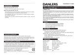
2.1 Processor Unit
2.1.1 How to connect cables to terminals on the processor unit
Use screws (M3x6, supplied) to
attach the wiring plate 1 and wir-
ing plate 2 assy to the processor
unit. Connect the cables shown
below to the connectors at the
front of the processor unit. After
the connection, bind cables to
the appropriate fixing metal with
the cable ties (supplied).
For the cables from the monitor unit (type: DVI-D/D SLINK5M/10M (MU-190 only),
DSUB9P-X2-L5/10M) and ground wire, connect them to the processor unit directly
(without fixing to a wiring plate). Tighten the fixing screws on these connectors to pre-
vent disconnection from the processor unit.
Note: Connect the cables so that they do not interfere with the opening or closing of
the DVD tray.
Wiring plate 2 assy
Wiring plate 1
Slide the plate toward
the unit to hide LED
and switches.
2. WIRING
2-3
Cables connected at the wiring plate 1
• USB cables from the control units
• Printer cable
• LAN cable (type: DTI-C5E350 VCV) from the HUB-3000
• LAN cable (type: FR-FTPC-CY) from the HUB-100/MC-3000S
Cables connected at wiring plate 2 assy
• Power cable (Type: IEC60320-C13-L5M)
• LAN cable to the LAN3 port
(DVI1: DVI-D/D S-LINK cable,
COM1: DSUB9P-X2-L cable or DSUB9P-X2-A-L cable)
COM1
MU-190/MU-231
(DVI3: DVI-D/D S-LINK cable
or DVI-BNCX5-L2000 cable,
COM2: DSUB9P-X2-L cable)
DVI3
USB1
RCU-024/026
(TS-20-071-1 cable)
USB2/3
Optional control unit
RCU-024/026
(TS-20-071-1 cable)
HUB-3000
(DTI-C5E350 VCV
cable)
LAN1
LAN2
HUB-100/MC-3000S
(FR-FTPC-CY cable,
within 50m)
DVI1
COM2
Cable clamp
Ground wire
(IV-2sq.,
local supply)
Power cable
(IEC60320-C13-
L5M cable)
USB4
For USB printer
LAN3
Not used.
DVI2
(DVI2: DVI-D/D S-LINK cable
or DVI-BNCX5-L2000 cable)
MU-190/MU-231
MU-190/MU-231/HD26T21-MMD-MA4-FAGA
2. WIRING
2-4
Fabricating LAN cable
Fabricate the LAN cable (FR-FTPC-CY, DTI-C5E350 VCV), as shown below. (Wrap
both edges of the armor with vinyl tape.) Confirm that the shield of the cable touches
to the shell of the modular plug.
Armor
55
Inner vinyl sheath
Outer vinyl sheath
Wrap vinyl tape
30
Using special crimping tool
MPT5-8 (PANDUIT CORP.),
crimp the modular plug.
Finally check the plug visually.
1 WHT/GRN
2 GRN
3 WHT/ORG
4 BLU
5 WHT/BLE
6 ORG
7 WHT/BRN
8 BRN
WHT/ORG 1
ORG 2
WHT/GRN 3
BLU 4
WHT/BLE 5
GRN 6
WHT/BRN 7
BRN 8
1 WHT/ORG
2 ORG
3 WHT/GRN
4 BLU
5 WHT/BLE
6 GRN
7 WHT/BRN
8 BRN
WHT/ORG 1
ORG 2
WHT/GRN 3
BLU 4
WHT/BLE 5
GRN 6
WHT/BRN 7
BRN 8
Expose inner vinyl sheath.
[Cross cable]
[Straight cable]
Remove the outer sheath by
approx 25 mm. Be careful
not to damage inner shield
and cores.
Fold back the shield, wrap it
onto the outer sheath and
cut it, leaving 9 mm.
12
3
25mm
approx. 9mm
4
5
6
approx. 9mm
approx. 11mm
Drain wire
Fold back drain wire and
cut it, leaving 9 mm.
Straighten and flatten the
core in order and cut them,
leaving 11 mm.
Insert the cable into the modular
plug so that the folded part of
the shield enters into the plug
housing. The drain wire should
be located on the tab side of
the jack.
7
  • Page 1 1
  • Page 2 2
  • Page 3 3
  • Page 4 4
  • Page 5 5
  • Page 6 6
  • Page 7 7
  • Page 8 8
  • Page 9 9
  • Page 10 10
  • Page 11 11
  • Page 12 12
  • Page 13 13
  • Page 14 14
  • Page 15 15
  • Page 16 16
  • Page 17 17
  • Page 18 18
  • Page 19 19
  • Page 20 20
  • Page 21 21
  • Page 22 22
  • Page 23 23
  • Page 24 24
  • Page 25 25
  • Page 26 26
  • Page 27 27
  • Page 28 28
  • Page 29 29
  • Page 30 30
  • Page 31 31
  • Page 32 32
  • Page 33 33
  • Page 34 34
  • Page 35 35
  • Page 36 36
  • Page 37 37
  • Page 38 38
  • Page 39 39
  • Page 40 40
  • Page 41 41
  • Page 42 42
  • Page 43 43
  • Page 44 44
  • Page 45 45
  • Page 46 46
  • Page 47 47
  • Page 48 48
  • Page 49 49
  • Page 50 50
  • Page 51 51
  • Page 52 52
  • Page 53 53
  • Page 54 54
  • Page 55 55
  • Page 56 56
  • Page 57 57
  • Page 58 58
  • Page 59 59
  • Page 60 60
  • Page 61 61
  • Page 62 62
  • Page 63 63
  • Page 64 64
  • Page 65 65
  • Page 66 66
  • Page 67 67
  • Page 68 68
  • Page 69 69
  • Page 70 70
  • Page 71 71
  • Page 72 72
  • Page 73 73
  • Page 74 74
  • Page 75 75
  • Page 76 76
  • Page 77 77
  • Page 78 78
  • Page 79 79
  • Page 80 80
  • Page 81 81
  • Page 82 82
  • Page 83 83
  • Page 84 84
  • Page 85 85
  • Page 86 86
  • Page 87 87
  • Page 88 88
  • Page 89 89
  • Page 90 90
  • Page 91 91
  • Page 92 92
  • Page 93 93

Furuno FMD3200 Installation guide

Category
Navigational compasses
Type
Installation guide
This manual is also suitable for

Ask a question and I''ll find the answer in the document

Finding information in a document is now easier with AI