Elmo 1.1 User manual
- Category
- Noise Reduction Machine
- Type
- User manual
This manual is also suitable for


Notice
This guide is delivered subject to the following conditions and restrictions:
This guide contains proprietary information belonging to Elmo Motion Control Ltd.
Such information is supplied solely for the purpose of assisting users of the Guitar
servo drive in its installation.
The text and graphics included in this manual are for the purpose of illustration and
reference only. The specifications on which they are based are subject to change
without notice.
Elmo Motion Control and the Elmo Motion Control logo are trademarks of Elmo
Motion Control Ltd.
Information in this document is subject to change without notice.
Document. no.
MAN-GUIIG (Ver. 1.1)
Copyright 2008
Elmo Motion Control Ltd.
All rights reserved.
Guitar Catalog Number
Related Products:
Evaluation Board Catalog Number
Evaluation Board User Manual
To be assigned
In development
Revision History:
Ver. 1.0 April 2008
Ver. 1.1 July 2008. Heat dissipation data added in Chapter 3.
Elmo Motion Control Ltd.
64 Gisin St., P.O. Box 463
Petach Tikva 49103
Israel
Tel: +972 (3) 929-2300
Fax: +972 (3) 929-2322
Elmo Motion Control Inc.
1 Park Drive, Suite 12
Westford, MA 01886
USA
Tel: +1 (978) 399-0034
Fax: +1 (978) 399-0035
Elmo Motion Control GmbH
Steinkirchring 1
D-78056, Villingen-Schwenningen
Germany
Tel: +49 (0) 7720-85 77 60
Fax: +49 (0) 7720-85 77 70
www.elmomc.com

Contents
Chapter 1: Safety Information........................................................................................1-1
1.1 Warnings............................................................................................................1-2
1.2 Cautions..............................................................................................................1-2
1.3 Directives and Standards..................................................................................1-3
1.4 CE Mark Conformance .....................................................................................1-3
1.5 Warranty Information.......................................................................................1-3
Chapter 2: Introduction....................................................................................................2-1
2.1 Drive Description..............................................................................................2-1
2.2 Product Features................................................................................................2-2
2.2.1 Current Control...........................................................................................2-2
2.2.2 Velocity Control...........................................................................................2-2
2.2.3 Position Control...........................................................................................2-2
2.2.4 Advanced Position Control........................................................................2-2
2.2.5 Communication Options............................................................................2-2
2.2.6 Feedback Options........................................................................................2-3
2.2.7 Fault Protection............................................................................................2-3
2.3 System Architecture..........................................................................................2-4
2.4 How to Use this Guide......................................................................................2-5
Chapter 3: Installation......................................................................................................3-1
3.1 Site Requirements..............................................................................................3-1
3.2 Unpacking the Drive Components..................................................................3-1
3.3 Pinouts................................................................................................................3-2
3.3.1 Connector Types..........................................................................................3-2
3.3.2 Connector J1.................................................................................................3-3
3.3.3 Connector J2.................................................................................................3-4
3.4 Mounting the Guitar.........................................................................................3-5
3.5 Integrating the Guitar on a PCB.......................................................................3-6
3.5.1 Traces ............................................................................................................3-6
3.5.2 Grounds and Returns..................................................................................3-6
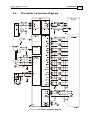
3.6 The Guitar Connection Diagram......................................................................3-8
3.7 Main Power and Motor Power.........................................................................3-9
3.7.1 Connecting Motor Power...........................................................................3-9
3.7.2 Connecting Main Power...........................................................................3-10
3.8 Auxiliary Supply (for drive logic)...............................................................3-10
3.8.1 Single Supply.............................................................................................3-11
3.8.2 Separate Auxiliary Supply.......................................................................3-11
3.8.3 Shared Supply............................................................................................3-12
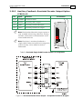
3.9 Main Feedback.................................................................................................3-13
3.10 Auxiliary Feedback .........................................................................................3-21
3.10.1 Main and Auxiliary Feedback Combinations .......................................3-22
3.10.2 Auxiliary Feedback: Emulated Encoder Output Option (YA[4]=4)...3-23
3.10.3 Auxiliary Feedback: Single-Ended Encoder Input Option (YA[4]=2)3-25
3.10.4 Auxiliary Feedback: Pulse-and-Direction Input Option (YA[4]=0)...3-27
Guitar Installation Guide
MAN-GUIIG (Ver. 1.1)
i

3.11 I/Os...................................................................................................................3-29
3.11.1 Digital Input...............................................................................................3-30
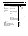
3.11.2 Digital Output............................................................................................3-32
3.11.3 Analog Input..............................................................................................3-34
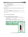
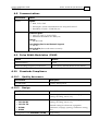
3.12 Communications..............................................................................................3-35
3.12.1 RS-232 Communication............................................................................3-35
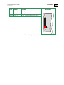
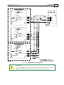
3.12.2 CANopen Communication......................................................................3-36
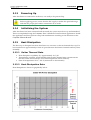
3.13 Powering Up....................................................................................................3-39
3.14 Initializing the System ....................................................................................3-39
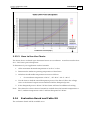
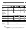
3.15 Heat Dissipation..............................................................................................3-39
3.15.1 Guitar Thermal Data.................................................................................3-39
3.15.2 Heat Dissipation Data...............................................................................3-39
3.15.3 How to Use the Charts..............................................................................3-41
3.16 Evaluation Board and Cable Kit ....................................................................3-41
Appendix: Guitar Technical Specifications.................................................................A-1
A.1 Features .............................................................................................................A-1
A.1.1
Motion Control Modes..............................................................................A-1
A.1.2 Advanced Positioning Control Modes....................................................A-1
A.1.3 Advanced Filters and Gain Scheduling...................................................A-1
A.1.4 Fully Programmable..................................................................................A-1
A.1.5 Feedback Options.......................................................................................A-1
A.1.6 Input/Output..............................................................................................A-2
A.1.7 Built-In Protection......................................................................................A-2
A.1.8 Accessories..................................................................................................A-3
A.1.9 Status Indication.........................................................................................A-3
A.1.10 Automatic Procedures...............................................................................A-3
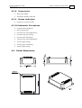
A.2 Guitar Dimensions...........................................................................................A-3
A.3 Power Ratings...................................................................................................A-4
A.4 Environmental Conditions..............................................................................A-5
A.4.1 Auxiliary Supply........................................................................................A-5
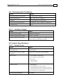
A.5 Control Specifications......................................................................................A-5
A.5.1 Current Loop...............................................................................................A-5
A.5.2 Velocity Loop..............................................................................................A-6
A.5.3 Position Loop..............................................................................................A-6
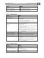
A.6 Feedbacks..........................................................................................................A-7
A.6.1 Feedback Supply Voltage..........................................................................A-7
A.6.2 Main Feedback Options.............................................................................A-7
A.6.2.1 Incremental Encoder Input......................................................................A-7
A.6.2.2 Digital Halls................................................................................................... A-8
A.6.2.3 Interpolated Analog Encoder (Sine/Cosine)................................... A-8
A.6.2.4 Resolver...........................................................................................................A-9
A.6.2.5 Tachometer*................................................................................................... A-9
A.6.2.6 Potentiometer.............................................................................................. A-10
A.6.3 Auxiliary Feedback Port (output mode YA[4]= 4)..............................A-10
A.6.4 Auxiliary Feedback Port (input mode YA[4]= 2, 0).............................A-11
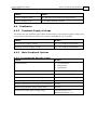
A.7 I/Os..................................................................................................................A-12
A.7.1 Digital Input Interfaces............................................................................A-12
A.7.2 Digital Output Interface..........................................................................A-13
Guitar Installation Guide Contents
MAN-GUIIG (Ver. 1.1)
ii

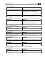
A.7.3 Analog Input.............................................................................................A-13
A.8 Communications.............................................................................................A-14
A.9 Pulse Width Modulation (PWM)..................................................................A-14
A.10 Standards Compliance...................................................................................A-14
A.10.1 Quality Assurance....................................................................................A-14
A.10.2 Design ........................................................................................................A-14
A.10.3 Safety..........................................................................................................A-15
A.10.4 EMC............................................................................................................A-15
A.10.5 Workmanship ...........................................................................................A-15
A.10.6 PCB.............................................................................................................A-15
A.10.7 Packing.......................................................................................................A-15
A.10.8 WEEE*........................................................................................................A-15
A.10.9 RoHS...........................................................................................................A-15
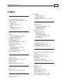
Index....................................................................................................................................I-1
Guitar Installation Guide Contents
MAN-GUIIG (Ver. 1.1)
iii

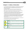
Chapter 1: Safety Information
In order to operate the Guitar servo drive safely, it is imperative that you implement the
safety procedures included in this installation guide. This information is provided to
protect you and to keep your work area safe when operating the Guitar and
accompanying equipment.
Please read this chapter carefully before you begin the installation process.
Before you start, ensure that all system components are connected to earth ground.
Electrical safety is provided through a low-resistance earth connection.
Only qualified personnel may install, adjust, maintain and repair the servo drive. A
“qualified person” has the knowledge and authorization to perform tasks such as
transporting, assembling, installing, commissioning and operating motors.
The Guitar servo drive contains electrostatic-sensitive components that can be damaged
if handled incorrectly. To prevent any electrostatic damage, avoid contact with highly
insulating materials, such as plastic film and synthetic fabrics. Place the product on a
conductive surface and ground yourself in order to discharge any possible static
electricity build-up.
To avoid any potential hazards that may cause severe personal injury or damage to the
product during operation, keep all covers and cabinet doors shut.
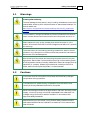
The following safety symbols are used in this manual:
Warning:
This information is needed to avoid a safety hazard, which might cause
bodily injury.
Caution:
This information is necessary for preventing damage to the product or
to other equipment.
Note:
This is auxiliary information that ensures the correct operation of the
equipment.
Guitar Installation Guide
MAN-GUIIG (Ver. 1.1)
1-1

1.1 Warnings
Cleaning after soldering
To avoid damage to the product’s acrylic coating, the Bassoon must not be
cleaned after soldering with soluble solvents or water-based cleaners. For
further details see:
www.elmomc.com/applications/article/Soldering-and-Cleaning_Application-
Note.pdf
To avoid electric arcing and hazards to personnel and electrical contacts,
never connect/disconnect the servo drive while the power source is on.
Power cables can carry a high voltage, even when the motor is not in
motion. Disconnect the Guitar from all voltage sources before it is opened
for servicing.
The Guitar servo drive contains grounding conduits for electric current
protection. Any disruption to these conduits may cause the instrument to
become hot (live) and dangerous.
After shutting off the power and removing the power source from your
equipment, wait at least 1 minute before touching or disconnecting parts
of the equipment that are normally loaded with electrical charges (such as
capacitors or contacts). Measuring the electrical contact points with a
meter, before touching the equipment, is recommended.
1.2 Cautions
The Guitar servo drive contains hot surfaces and electrically-charged
components during operation.
The maximum DC power supply connected to the instrument must
comply with the parameters outlined in this guide.
When connecting the Guitar to an approved 12~195 VDC auxiliary power
supply, connect it through a line that is separated from hazardous live
voltages using reinforced or double insulation in accordance with
approved safety standards.
Before switching on the Guitar, verify that all safety precautions have
been observed and that the installation procedures in this manual have
been followed.
Guitar Installation Guide Safety Information
MAN-GUIIG (Ver. 1.1)
1-2

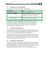
1.3 Directives and Standards
The Guitar conforms to the following industry safety standards:
Safety Standard Item
In compliance with UL508c Power Conversion Equipment
In compliance with UL840
Insulation Coordination, Including Clearance and
Creepage Distances of Electrical Equipment
In compliance with UL60950-1
(formerly UL1950)
Safety of Information Technology Equipment,
Including Electrical Business Equipment
In compliance with EN60204-1 Low Voltage Directive, 73/23/EEC
The Guitar servo drive has been developed, produced, tested and documented in
accordance with the relevant standards. Elmo Motion Control is not responsible for any
deviation from the configuration and installation described in this documentation.
Furthermore, Elmo is not responsible for the performance of new measurements or
ensuring that regulatory requirements are met.
1.4 CE Mark Conformance
The Guitar servo drive is intended for incorporation in a machine or end product. The
actual end product must comply with all safety aspects of the relevant requirements of
the European Safety of Machinery Directive 98/37/EC as amended, and with those of the
most recent versions of standards EN60204-1 and EN292-2 at the least.
According to Annex III of Article 13 of Council Directive 93/68/EEC, amending Council
Directive 73/23/EEC concerning electrical equipment designed for use within certain
voltage limits, the Guitar meets the provisions outlined in Council Directive 73/23/EEC.
The party responsible for ensuring that the equipment meet the limits required by EMC
regulations is the manufacturer of the end product.
1.5 Warranty Information
The products covered in this manual are warranted to be free of defects in material and
workmanship and conform to the specifications stated either within this document or in
the product catalog description. All Elmo drives are warranted for a period of 12 months
from the time of installation, or 18 months from time of shipment, whichever comes first.
No other warranties, expressed or implied — and including a warranty of
merchantability and fitness for a particular purpose — extend beyond this warranty.
Guitar Installation Guide Safety Information
MAN-GUIIG (Ver. 1.1)
1-3

Guitar Installation Guide Introduction
MAN-GUIIG (Ver. 1.1)
2-1
Chapter 2: Introduction
This installation guide describes the Guitar servo drive and the steps for its wiring,
installation and power-up. Following these guidelines ensures maximum functionality of
the drive and the system to which it is connected.
2.1 Drive Description
The Guitar series of digital servo drives is designed to deliver “the highest density of
power and intelligence”. The Guitar delivers up to 4.8 kW of continuous power or
5.4 kW of peak power in a 119. 6 cc (6.95 in³) package (80 x 24.5 x 61 mm or 3.15" x 0.965"
x 2.4").
The Guitar is designed for OEMs. It operates from a DC power source in current, velocity,
position and advanced position modes, in conjunction with a permanent-magnet
synchronous brushless motor, DC brush motor, linear motor or voice coil. It is designed for
use with any type of sinusoidal and trapezoidal commutation, with vector control. The
Guitar can operate as a stand-alone device or as part of a multi-axis system in a distributed
configuration on a real-time network.
The Guitar drive is easily set up and tuned using Elmo’s Composer software tools. This
Windows-based application enables users to quickly and simply configure the servo drive
for optimal use with their motor. The Guitar, as part of the
SimplIQ product line, is fully
programmable with the Elmo Metronome motion control language.
Power to the Guitar is provided by a 12 ~ 195 VDC isolated DC power source (not included
with the Guitar). A “smart” control-supply algorithm enables the Guitar to operate with
only one power supply with no need for an auxiliary power supply for the logic.
If backup functionality is required for storing control parameters in case of power-loss, an
external 12 ~ 195 VDC isolated supply should be connected (via the +VL terminal on the
Guitar) providing maximum flexibility and backup functionality when needed.
Note: This backup power supply can operate from any voltage source within the 12 ~ 195
VDC range. This is much more flexible than a standard 24 VDC power supply requirement.
If back-up power is not needed, two terminals (VP and VL) are shorted so that the main
power supply will also power the control/logic supply. In this way there is no need for a
separate control/logic supply.
The Guitar is a PCB mounted device which enables efficient and economic implementation.
The Guitar is available in two models:
The Standard Guitar is a basic servo drive which operates in current, velocity and
position modes including Follower and PT & PVT. It operates simultaneously via RS-
232 and CANopen DS 301, DS 305, DS 402 communications and features a third-
generation programming environment.

Guitar Installation Guide Introduction
MAN-GUIIG (Ver. 1.1)
2-2
The Advanced Guitar includes all the motion capabilities and communication options
included in the Standard model, as well as advanced positioning capabilities: ECAM,
Dual Loop and increased program size.
Both versions operate with RS-232 and CANopen communication.
2.2 Product Features
2.2.1 Current Control
Fully digital
Sinusoidal commutation with vector control or trapezoidal commutation
with encoder and/or digital Hall sensors.
12-bit current loop resolution.
Automatic gain scheduling, to compensate for variations in the DC bus
power supply.
2.2.2 Velocity Control
Fully digital.
Programmable PI and FFW (feed forward) control filters.
Sample rate two times current loop sample time.
“On-the-fly” gain scheduling.
Automatic, manual and advanced manual tuning and determination of
optimal gain and phase margins.
2.2.3 Position Control
Programmable PIP control filter.
Programmable notch and low-pass filters.
Position follower mode for monitoring the motion of the slave axis
relative to a master axis, via an auxiliary encoder input.
Pulse-and-direction inputs.
Sample time: four times that of the current loop.
Fast event capturing inputs.
PT and PVT motion modes.
Fast output compare (OC).
2.2.4 Advanced Position Control
This relates to the Advanced model only.
Position-based and time-based ECAM mode that supports a non-linear
follower mode, in which the motor tracks the master motion using an
ECAM table stored in flash memory.
Dual (position/velocity) loop.
2.2.5 Communication Options
Depending on the application, Guitar users can select from two communication options:
RS-232 serial communication.
CANopen for fast communication in a multi-axis distributed environment.

Guitar Installation Guide Introduction
MAN-GUIIG (Ver. 1.1)
2-3
2.2.6 Feedback Options
• Incremental Encoder – up to 20 Mega-Counts (5 Mega-Pulse) per second
• Digital Halls – up to 2 kHz
• Incremental Encoder with Digital Halls for commutation – up to 20 Mega-
Counts per second for encoder
• Interpolated Analog Sine/Cosine Encoder – up to 250 kHz (analog signal)
Internal interpolation - up to x4096
Automatic correction of amplitude mismatch, phase mismatch, signals
offset
Auxiliary emulated, unbuffered, single-ended, encoder output
• Resolver
Programmable 10~15 bit resolution
Up to 512 revolutions per second (RPS)
Auxiliary emulated, unbuffered, single-ended, encoder output
• Tachometer, Potentiometer
• Elmo drives provide supply voltage for all the feedback options
2.2.7 Fault Protection
The Guitar includes built-in protection against possible fault conditions, including:
• Software error handling
• Status reporting for a large number of possible fault conditions
• Protection against conditions such as excessive temperature, under/over
voltage, loss of commutation signal, short circuits between the motor power
outputs and between each output and power input/return
• Recovery from loss of commutation signals and from communication errors

Guitar Installation Guide Introduction
MAN-GUIIG (Ver. 1.1)
2-4
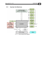
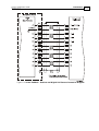
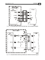
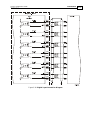
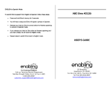
2.3 System Architecture
Figure 2-1: Guitar System Block Diagram

Guitar Installation Guide Introduction
MAN-GUIIG (Ver. 1.1)
2-5
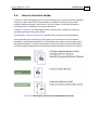
2.4 How to Use this Guide
In order to install and operate your Elmo Guitar servo drive, you will use this manual in
conjunction with a set of Elmo documentation. Installation is your first step; after
carefully reading the safety instructions in the first chapter, the following chapters
provide you with installation instructions as follows:
Chapter 3, Installation, provides step-by-step instructions for unpacking, mounting,
connecting and powering up the Guitar.
The Appendix, Technical Specifications, lists all the drive ratings and specifications.
Upon completing the instructions in this guide, your Guitar servo drive should be
successfully mounted and installed. From this stage, you need to consult higher-level
Elmo documentation in order to set up and fine-tune the system for optimal operation.
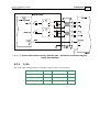
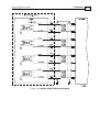
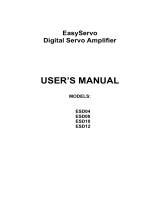
The following figure describes the accompanying documentation that you will require.
Figure 2-2: Elmo Digital Servo Drive Documentation Hierarchy

Guitar Installation Guide Introduction
MAN-GUIIG (Ver. 1.1)
2-6
As depicted in the previous figure, this installation guide is an integral part of the Guitar
documentation set, comprising:
The SimplIQ Software Manual, which describes the comprehensive software
used with the Guitar.
The SimplIQ Command Reference Manual, which describes, in detail, each
software command used to manipulate the Guitar motion controller.
The Composer Software Manual, which includes explanations of all the
software tools that are part of Elmo’s Composer software environment.
The Guitar Evaluation Board User Guide contains information about how to
use the Guitar Evaluation Board and Cable Kit. (This user guide is currently
being developed.)

Chapter 3: Installation
3.1 Site Requirements
You can guarantee the safe operation of the Guitar by ensuring that it is installed in an
appropriate environment.
Feature Value
Ambient operating temperature 0 °C to 40 °C (32 °F to 104 °F)
Maximum relative humidity 90% non-condensing
Operating area atmosphere No flammable gases or vapors permitted in area
Models for extended environmental conditions are available.
The Guitar dissipates its heat by convection. The maximum operating ambient
temperature of 0 °C to 40 °C (32 °F to 104 °F) must not be exceeded.
3.2 Unpacking the Drive Components
Before you begin working with the Guitar, verify that you have all of its components, as
follows:
The Guitar servo drive
The Composer software and software manual
The Guitar is shipped in a cardboard box with styrofoam protection.
To unpack the Guitar:
1. Carefully remove the servo drive from the box and the Styrofoam.
2. Check the drive to ensure that there is no visible damage to the instrument. If any damage
has occurred, report it immediately to the carrier that delivered your drive.
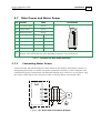
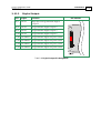
3. To ensure that the Guitar you have unpacked is the appropriate type for your
requirements, locate the part number sticker on the side of the Guitar. It looks like this:
Guitar Installation Guide
MAN-GUIIG (Ver. 1.1)
3-1

The part number at the top gives the type designation as follows:
Verify that the Guitar type is the one that you ordered, and ensure that the voltage meets
your specific requirements.
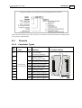
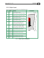
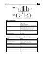
3.3 Pinouts
3.3.1 Connector Types
No.
Pins
Type
Port
Function
Connector Location
2x16 J1 I/O, COMM,
Auxiliary Feedback
15 J2 Main Feedback,
Analog Input, LED
6 VL Auxiliary power input
6 VP+ Positive power input
6 PR Power input return
4 PE Protective earth
6 M1 Motor power output 1
6 M2 Motor power output 2
2
2 mm Pitch
0.51 mm SQ
M3 Motor power output 3
Guitar Installation Guide Installation
MAN-GUIIG (Ver. 1.1)
3-2

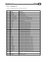
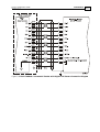
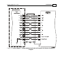
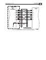
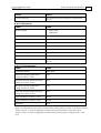
3.3.2 Connector J1
Connector J1: Main Feedback and Analog Input functions
Pin Signal Function
J1/1 RS232_RX RS232 receive
J1/2 RS232_TX RS232 Transmit
J1/3 RS232_COMRET Communication return
J1/4 AUX PORT CHA Auxiliary port CHA (bidirectional)
J1/5 AUX PORT CHB Auxiliary port CHB (bidirectional)
J1/6 SUPRET Supply return
J1/7 OUT1 Programmable digital output 1
J1/8 OUT2 Programmable digital output 2
J1/9 OUT3 Programmable digital output 3
J1/10 OUT4 Programmable digital output 4
J1/11 IN1 Programmable digital input 1
J1/12 IN2 Programmable digital input 2
J1/13 IN3 Programmable digital input 3
J1/14 IN4 Programmable digital input 4
J1/15 IN5 Programmable digital input 5
J1/16 IN6 Programmable digital input 6
J1/17 INRET6 Programmable digital input 6 return
J1/18 INRET5 Programmable digital input 5 return
J1/19 INRET4 Programmable digital input 4 return
J1/20 INRET3 Programmable digital input 3 return
J1/21 INRET2 Programmable digital input 2 return
J1/22 INRET1 Programmable digital input 1 return
J1/23 OUTRET4 Programmable digital output 4 return
J1/24 OUTRET3 Programmable digital output 3 return
J1/25 OUTRET2 Programmable digital output 2 return
J1/26 OUTRET1 Programmable digital output 1 return
J1/27 +5 V Encoder +5 V supply voltage. Maximum output current:
200 mA.
J1/28 COMRET Common return
Guitar Installation Guide Installation
MAN-GUIIG (Ver. 1.1)
3-3

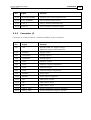
Pin Signal Function
J1/29 AUX PORT INDEX Auxiliary port index (bidirectional)
J1/30 CAN_COMRET CAN communication return
J1/31 CAN_L CAN_L busline (dominant low)
J1/32 CAN_H CAN_H busline (dominant high)
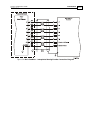
3.3.3 Connector J2
Connector J2: Communications, Auxiliary Feedback and I/O functions
Pin Signal Function
J2/1 +5V Encoder/Hall +5V supply voltage.
Maximum output current: 200 mA.
J2/2 SUPRET Supply return
J2/3 ANALIN1+ Analog input 1+
J2/4 ANALIN1- Analog input 1-
J2/5 CHA Channel A input
J2/6 CHA- Channel A input complement
J2/7 CHB Channel B input
J2/8 CHB- Channel B input complement
J2/9 INDEX+ Index input
J2/10 INDEX- Index input complement
J2/11 HA Hall sensor A input
J2/12 HB Hall sensor B input
J2/13 HC Hall sensor C input
J2/14 LED_2_OUT Bi-color indication output 2 (Cathode)
J2/15 LED_1_OUT Bi-color indication output 1 (Anode)
Guitar Installation Guide Installation
MAN-GUIIG (Ver. 1.1)
3-4

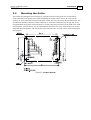
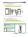
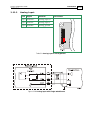
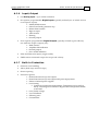
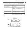
3.4 Mounting the Guitar
The Guitar was designed for mounting on a printed circuit board (PCB). It is connected by
2 mm pitch 0.51 mm square pins. When designing the Guitar into a device, be sure to leave
about 1 cm (0.4") outward from the heatsink to enable free air convection around the Guitar. We
recommend that the Guitar be soldered directly to the board. Alternatively, though this is not
recommended, the Guitar can be attached to socket connectors mounted on the PCB. If the PCB
is enclosed in a metal chassis, we recommend that the Guitar be screw-mounted to it as well to
help with heat dissipation. The Guitar has screw-mount holes on each corner of the heatsink for
this purpose.
Figure 3-1: Guitar Footprint
Guitar Installation Guide Installation
MAN-GUIIG (Ver. 1.1)
3-5

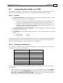
3.5 Integrating the Guitar on a PCB
The Guitar is designed to be mounted on a PCB, either by soldering its pins directly to the
PCB or by using suitable socket connectors. In both cases the following rules apply:
3.5.1 Traces
1. The size of the traces on the PCB (thickness and width) is determined by the current
carrying capacity required by the application.
The rated continuous current limit (Ic)of the Guitar is the current used for sizing
the motor traces (M1, M2, M3 and PE) and power traces (VP+, PR and PE).
For control, feedbacks and Inputs/ outputs conductors the actual current is very
small but “generous” thickness and width of the conductors will contribute to a
better performance and lower interferences.
2. The traces should be as short as possible to minimize EMI and to minimize the heat
generated by the conductors.
3. The spacing between the high voltage conductors (VP+, PR, M1, M2, M3, VL) must be
at least:
Surface layer: 1.5 mm
Internal layer: 0.5 mm
Complying with the rules above will help satisfy UL safety standards, MIL-STD-275 and the
IPC-D-275 standard for non-coated conductors, operating at voltages lower than 200 VDC
and at “unlimited altitudes” (above 10,000 meters – 30,000 feet).
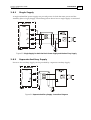
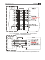
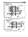
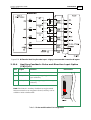
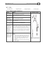
3.5.2 Grounds and Returns
The “Returns” of the Guitar are structured internally in a star configuration. The returns in
each functional block are listed below:
Functional Block Return Pin
Power PR (Power Return)
Internal Switch Mode P.S. PR (Power Return)
RS232 Communications RS232_COMRET (J1/3)
CAN Communications CAN_COMRET (J1/30)
Control section COMRET (J1/28)
Main Feedback SUPRET (J2/2)
Aux. Feedback SUPRET (J1/6)
Analog input ANLRET (J2/2)
The returns above are all shorted within the Guitar in a topology that results in optimum
performance.
1. When wiring the traces of the above functions, on the Integration Board, the Returns of
each function must be wired separately to its designated terminal on the Guitar. DO
NOT USE A COMMON GROUND PLANE. Shorting the commons on the Integration
Board may cause performance degradation (ground loops, etc).
Guitar Installation Guide Installation
MAN-GUIIG (Ver. 1.1)
3-6
Page is loading ...
Page is loading ...
Page is loading ...
Page is loading ...
Page is loading ...
Page is loading ...
Page is loading ...
Page is loading ...
Page is loading ...
Page is loading ...
Page is loading ...
Page is loading ...
Page is loading ...
Page is loading ...
Page is loading ...
Page is loading ...
Page is loading ...
Page is loading ...
Page is loading ...
Page is loading ...
Page is loading ...
Page is loading ...
Page is loading ...
Page is loading ...
Page is loading ...
Page is loading ...
Page is loading ...
Page is loading ...
Page is loading ...
Page is loading ...
Page is loading ...
Page is loading ...
Page is loading ...
Page is loading ...
Page is loading ...
Page is loading ...
Page is loading ...
Page is loading ...
Page is loading ...
Page is loading ...
Page is loading ...
Page is loading ...
Page is loading ...
Page is loading ...
Page is loading ...
Page is loading ...
Page is loading ...
Page is loading ...
Page is loading ...
Page is loading ...
Page is loading ...
Page is loading ...
-
 1
1
-
 2
2
-
 3
3
-
 4
4
-
 5
5
-
 6
6
-
 7
7
-
 8
8
-
 9
9
-
 10
10
-
 11
11
-
 12
12
-
 13
13
-
 14
14
-
 15
15
-
 16
16
-
 17
17
-
 18
18
-
 19
19
-
 20
20
-
 21
21
-
 22
22
-
 23
23
-
 24
24
-
 25
25
-
 26
26
-
 27
27
-
 28
28
-
 29
29
-
 30
30
-
 31
31
-
 32
32
-
 33
33
-
 34
34
-
 35
35
-
 36
36
-
 37
37
-
 38
38
-
 39
39
-
 40
40
-
 41
41
-
 42
42
-
 43
43
-
 44
44
-
 45
45
-
 46
46
-
 47
47
-
 48
48
-
 49
49
-
 50
50
-
 51
51
-
 52
52
-
 53
53
-
 54
54
-
 55
55
-
 56
56
-
 57
57
-
 58
58
-
 59
59
-
 60
60
-
 61
61
-
 62
62
-
 63
63
-
 64
64
-
 65
65
-
 66
66
-
 67
67
-
 68
68
-
 69
69
-
 70
70
-
 71
71
-
 72
72


Elmo 1.1 User manual
- Category
- Noise Reduction Machine
- Type
- User manual
- This manual is also suitable for
Ask a question and I''ll find the answer in the document
Finding information in a document is now easier with AI
Related papers
-
Elmo X3X-WUSBMDL User manual
-
-
-
-
-
-
-
-
-
Other documents
-
König SEC-GL10 Datasheet
-
 Enabling Devices 2135 User manual
-
 Varedan Technologies VSA-1530-2 Product User Manual
-
 CNC4PC C82 Multifunction Cnc Board User manual
-
Applied Motion Products TSM23S User guide
-
MYACTUATOR MC series User manual
-
Applied Motion Products 920-0079B User guide
-
 Speeder Motion EasyServo Series User manual
-
MTS Systems Series TBF-R User manual
-
 RoboteQ AX2850 User manual


