Hobbico NexSTAR mini EP RxR Assembly Manual And Use And Care
- Category
- Toys & accessories
- Type
- Assembly Manual And Use And Care

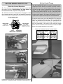
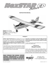
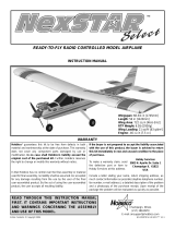
Wingspan: 44 in [1120mm]
Wing Area: 296 sq in [19.1 dm
2
]
Weight: 25–28 oz [710–790 g]
Wing Loading: 12.3–13.6 oz/sq ft [37–42 g/dm
2
]
Length: 36.5 in [925mm]
Radio: 4+ Channel transmitter with micro receiver
Motor: SuperTigre
®
400 Brushless
READ THROUGH THIS MANUAL BEFORE STARTING CONSTRUCTION. IT CONTAINS IMPORTANT
INSTRUCTIONS AND WARNINGS CONCERNING THE ASSEMBLY AND USE OF THIS MODEL.
Copyright © 2009 HCAA0700Mnl v1.0
WARRANTY
Hobbico
®
guarantees this kit to be free from defects in
both material and workmanship at the date of purchase.
This warranty does not cover any component parts
damaged by use or modifi cation. In no case shall
Hobbico’s liability exceed the original cost of the
purchased kit. Further, Hobbico reserves the right to
change or modify this warranty without notice.
In that Hobbico has no control over the fi nal assembly
or material used for fi nal assembly, no liability shall
be assumed nor accepted for any damage resulting
from the use by the user of the fi nal user-assembled
product. By the act of using the user-assembled
product, the user accepts all resulting liability.
If the buyer is not prepared to accept the liability
associated with the use of this product, the buyer
is advised to return this kit immediately in new and
unused condition to the place of purchase.
To make a warranty claim, send the defective part or
item to Hobby Services at the address below:
Hobby Services
3002 N. Apollo Dr. Suite 1
Champaign IL 61822
USA
Include a letter stating your name, return shipping
address, as much contact information as possible
(daytime telephone number, fax number, e-mail address),
a detailed description of the problem and a photocopy of
the purchase receipt. Upon receipt of the package the
problem will be evaluated as quickly as possible.
®
Champaign, Illinois
(217) 398-8970
E-mail: [email protected]
™
™

2
Congratulations on your purchase of the Hobbico Mini NexSTAR
EP RxR! The Mini NexSTAR EP follows the huge success of the
larger .46 glow engine NexSTAR Select, but now in a smaller park
fl yer size. A powerful brushless outrunner motor, combined with
the latest lithium polymer battery technology, provides extended
fl ight times and quiet, clean electric fl ight. With an experienced
fl ight instructor by your side, the Mini NexSTAR EP can train you
to be a competent pilot in a minimum amount of time. As your
skill improves, the NexSTAR can be modifi ed for faster and more
aerobatic fl ight.
For the latest technical updates or manual corrections to the Mini
NexSTAR EP visit the Hobbico web site at www.hobbico.com.
Open the “Airplanes” link, then select the Mini NexSTAR EP ARF.
If there is new technical information or changes to this model a
“tech notice” box will appear in the upper left corner of the page.
IMPORTANT
Once mastered, piloting a model aircraft can be one of the
most rewarding hobbies around. However, it cannot be stated
strongly enough that, if you do not already know how to fl y an
R/C airplane, you will probably not be able to fl y this model
by yourself. It may appear to be easy, but over-controlling and
disorientation quickly overcome inexperienced fl iers, swiftly
ending their fi rst fl ight. The best thing you can do to ensure
success is to fi nd a fl ight instructor who will inspect your model
for airworthiness and provide fl ying lessons. If you haven’t
yet done so, contact the local hobby shop and ask them to
introduce you to an instructor or an R/C club representative.
If there is no club or experienced R/C pilot nearby, it would be
worth even a long drive to fi nd one—if only for just a few fl ight
lessons (then you’ll have an idea of what to expect).
AMA
We urge you to join the AMA (Academy of Model Aeronautics)
and a local R/C club. The AMA is the governing body of model
aviation and membership is required to fl y at AMA clubs. Though
joining the AMA provides many benefi ts, one of the primary
reasons to join is liability protection. Coverage is not limited to
fl ying at contests or on the club fi eld. It even applies to fl ying at
public demonstrations and air shows. Failure to comply with the
Safety Code (excerpts printed in the back of the manual) may
endanger insurance coverage. Additionally, training programs
and instructors are available at AMA club sites to help you get
started the right way. There are over 2,500 AMA chartered clubs
across the country. Contact the AMA at the address or toll-free
phone number below:
Academy of Model Aeronautics
5151 East Memorial Drive
Muncie, IN 47302-9252
Tele. (800) 435-9262
Fax (765) 741-0057
www.modelaircraft.org
IMPORTANT!!! Two of the most important things you can do to
preserve the radio controlled aircraft hobby are to avoid fl ying near
full-scale aircraft and avoid fl ying near or over groups of people.
PROTECT YOUR MODEL, YOURSELF &
OTHERS...FOLLOW THESE IMPORTANT
SAFETY PRECAUTIONS
1. Your Mini NexSTAR EP should not be considered a toy, but
rather a sophisticated, working model that functions very much
like a full-size airplane. Because of its performance capabilities,
the Mini NexSTAR EP, if not assembled and operated correctly,
could possibly cause injury to yourself or spectators and damage
to property.
2. You must assemble the model according to the instructions.
Do not alter or modify the model, as doing so may result in an
unsafe or unfl yable model. In a few cases the instructions may
differ slightly from the photos. In those instances the written
instructions should be considered as correct.
4. You must use an R/C radio system that is in fi rst-class condition,
and a correctly sized receiver and battery.
5. You must correctly install all R/C and other components so that
the model operates correctly on the ground and in the air.
6. You must check the operation of the model before every fl ight
to insure that all equipment is operating and that the model has
remained structurally sound. Be sure to check clevises or other
connectors often and replace them if they show any signs of
wear or fatigue.
7. If you are not an experienced pilot or have not fl own this type
of model before, we recommend that you get the assistance of
an experienced pilot in your R/C club for your fi rst fl ights. If
you’re not a member of a club, your local hobby shop has
information about clubs in your area whose membership includes
experienced pilots.
We, as the kit manufacturer, provide you with a top quality,
thoroughly tested kit and instructions, but ultimately the quality
and fl yability of your fi nished model depends on how you build
it; therefore, we cannot in any way guarantee the performance
of your completed model, and no representations are
expressed or implied as to the performance or safety of your
completed model.

3
MINI NEXSTAR EP
SUCCESS GUARANTEE
We are so confi dent that the Mini NexSTAR EP is the best almost-
ready-to-fl y trainer available that we make this guarantee: You will
successfully learn how to fl y with the Mini NexSTAR EP or we will
replace it with your choice of any Hobbico trainer of up to equal
value. All we ask is that you learn to fl y under the supervision
of a qualifi ed, club-designated instructor, follow normal safety
precautions, fl y at an AMA-chartered club and construct the kit
as outlined in the included instruction manual.
If for some reason, you fi nd the design and/or workmanship of
the Mini NexSTAR EP is not conducive to learning to fl y under
the conditions outlined above, contact Hobby Services, Monday
through Friday, 9AM to 5PM, to initiate the NexSTAR EP Select
replacement process. You must verify that all terms and conditions
of the fl ight guarantee have been met and provide signatures
from you and your AMA-club qualifi ed instructor.
TERMS FOR U.S. AND CANADA GUARANTEE ONLY
• Must fl y at an AMA chartered fi eld
Must fl y at an AMA chartered fi eld
•
Must fl y with a qualifi ed AMA-club instructor
•
Must be within 60 days of purchase date
•
Must provide a statement about the crash and signature
from the pilot and instructor
This guarantee is effective for 60 days from the purchase
date of the kit and does not cover incidental items (motor,
radio equipment and hardware, etc.). The kit, along with the
replacement verifi cation form and original purchase receipt
must be returned to Hobby Services for inspection no later than
60 days after purchase. Hobbico reserves the right to verify all
information provided. The Mini NexSTAR EP Success Guarantee
is only good for kits purchased and fl own in the United States
and Canada. Replacement trainer kit options are limited to fl at-
bottom wing trainer models available from Hobbico and only one
replacement kit per customer.
Contact Hobby Services at:
Hobby Services
3002 N. Apollo Drive, Suite 1
Champaign, IL 61822 U.S.A.
(217) 398-0007
www.hobbyservices.com
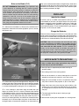
RADIO EQUIPMENT & BATTERY
All that is required to fi nish the Mini NexSTAR EP is a 4+ channel
radio system with micro or mini receiver, a fl ight battery and charger.
Part numbers for suggested equipment are provided below:
✰ Recommended: Futaba
®
6EX 6-Channel 2.4GHz Transmitter/
Receiver (FUTK6900) OR
✰ Economical: Futaba 4YF 4-Channel Micro FM/2 S3114
Servos (FUTJ36**)
✰ 1250mAh 11.1V LiPo Battery (SUPP1030)
Note: A Deans
®
Ultra Male Plug
®
to SuperTigre
®
ESC Adapter
(SUPM0040) is needed to connect a LiPo battery equipped
with a Deans connector to the included SuperTigre ESC.
✰ Great Planes
®
3S LiPo Smart Charger (GPMM3319)
OPTIONAL SUPPLIES & TOOLS
Optional tools shown in the assembly section of this manual are
very useful in the fi nal preparation of the plane and can be used
with future models as well.
✰ Great Planes C.G. Machine
™
(GPMR2400)
✰ Great Planes AccuThrow
™
Defl ection Meter (GPMR2405)
ORDERING REPLACEMENT PARTS
Replacement parts for the Hobbico Mini NexSTAR EP RxR are
available using the order numbers in the Replacement Parts
List that follows. The fastest, most economical service can be
provided by your hobby dealer or mail-order company. Parts may
also be ordered directly from Hobby Services, but full retail prices
and shipping and handling charges will apply. Illinois and Nevada
residents will also be charged sales tax.
If additional assistance is required for any reason contact
Product Support by e-mail at productsupport@hobbico.com, or
by telephone at (217) 398-8970.
Replacement Parts List
Order # Description
HCAA3140 Fuselage Set
HCAA3141 Wing Set
HCAA3142 Tail Surfaces
HCAA3143 Landing Gear
HCAA3144 Cowl
HCAA3145 Spinner
HCAA3146 Battery Hatch
HCAA3147 Wing Joiner
HCAA3148 Plastic Parts Set
HCAA3149 Nose Wheel Assembly
HCAA3150 Screw Set
GPMA2982 Servo Linkage Hardware Set
GPMQ6640 9x6 Propeller (2)
SUPG8040 400 Brushless Motor
SUPM1020 20A Brushless ESC
GPMM1210 NANO Servo
NOTE: Full-size plans are not available. You can download a
copy of this manual at www.hobbico.com.

4
ASSEMBLY
✰ 1. Remove the battery cover from the transmitter by pressing
on the cover and sliding it downward. Install four new “AA”
batteries, then replace the cover.
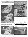
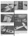
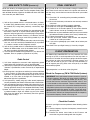
✰ 2. Fit the large vertical fi n tab part way into the slot in the
horizontal stabilizer. Slide the two pieces together into the aft
end of the fuselage, but leave the pieces only partially inserted
into the fuse. Fit the tail pushrods into the adjustable clevises
that are attached to the tail control horns. Slide the vertical fi n
and horizontal stabilizer as far forward as they can go.
✰ 3. There is a slot in the fuselage that the large tab on the
vertical fi n must pass through which locks the horizontal stabilizer
in place.
✰ 4. The tail surface servo arms must be perpendicular to the
servo cases as shown when adjusting the pushrod positions in
the clevises. If the servo arms are not perpendicular to the servo
cases, carefully move the arms by hand until they are.
20 30 4010
1
130907060 8050
23
100 110 120
45
170140 150 160
6
210180 190 200
78
300260240 250220 230
910
280 290270
11
ELEVATOR IS FLAT
✰ 5. Move the elevator pushrod further in or out in the clevis
until the elevator halves are in the neutral position. The neutral

5
position can be set by holding a straight edge (such as a ruler)
against the horizontal stabilizer and fi ne-tuning the elevator
pushrod in the clevis until the elevator rests fl at against the ruler.
Tighten the screw in the clevis. Do not over-tighten the screw!
✰ 6. Set the neutral position of the rudder in the same manner.
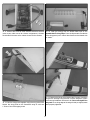
✰ 7. Secure the tail assembly in place by installing two 2.5mm
x 10mm self-tapping screws into the fuselage and through the
vertical fi n in the locations indicated by the two small holes in the
fi lm covering. Do not over-tighten the screw!
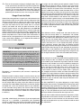
✰ 8. Install the main landing gear using two 3 x 12mm machine
screws. The tapered side of the gear should face the tail of
the plane.
✰ 9. Cut a piece from the included hook and loop material and
use it to install your receiver behind the servos (2.4GHz receiver
shown).
✰ 10. Tape the antennas to the side of the fuselage in the
orientation described in your radio manual. If you are using an
FM radio system, feed the antenna out through the cool air exit
hole in the bottom of the fuselage and tape it down the underside
of the fuse. Be sure that the antenna(s) will not contact the
pushrods or servo arms.

6
✰ 11. Connect the tail servo leads and ESC lead to the receiver
(refer to your radio manual for channel assignments). Connect
the included Y-harness to the aileron channel on the receiver.
✰ 12. Join the wing panels together using the wing joiner tube.
Secure the wing panel to the CenterCore wing rib with one
1.75mm x 5mm self-tapping screw.
✰ 13. Peel the backing from the double-sided tape on the
Speedbrakes Training Flaps. Press the fl aps onto the underside
of the wing panels just in front of the ailerons on the inboard side
as shown.
✰ 14. Connect the aileron servo leads to the Y-harness. Install the
wing on the fuselage using the 4mm x 25mm wing bolt. Tighten
the screw until additional resistance is felt. Do not overtighten the
wing bolt! The trailing edge of the wing will feel just slightly loose
when properly tightened.

7
CHARGE AND INSTALL
THE FLIGHT BATTERY
WARNING!! Read the entire instruction sheet included with
the battery and charger. Failure to follow all instructions could
cause permanent damage to the battery and its surroundings,
and cause bodily harm!
• ONLY use a LiPo approved charger. NEVER use a NiCd/
NiMH peak charger!
• NEVER leave battery unattended when charging!
• NEVER charge in excess of 4.20V per cell.
• ONLY charge through the “charge” lead. NEVER charge
through the “discharge” lead.
• NEVER charge at currents greater than 1C.
• ALWAYS set charger’s output volts to match battery volts.
• ALWAYS charge in a fi reproof location.
• NEVER trickle charge.
• NEVER allow battery temperature to exceed 150° F [65° C].
• NEVER disassemble or modify pack wiring in any way or
puncture cells.
• NEVER discharge below 2.5V per cell.
• NEVER place on combustible materials or leave unattended
during charge or discharge.
• ALWAYS KEEP OUT OF REACH OF CHILDREN.
✰ 1. Cut a 2" [57mm] piece of the loop side from the included self-
adhesive hook and loop material and stick it to your fl ight battery.
✰ 2. Remove the battery hatch from the bottom of the plane by
lifting the aft end of the hatch away from the fuse.
✰ 3. Install the fl ight battery onto the battery tray.
ESC OPERATING DIRECTIONS
To view the complete SuperTigre 25A brushless ESC manual,
visit www.supertigre.com.
Necessary Transmitter Settings
For proper ESC operation, it’s very important to set the
transmitter’s throttle channel adjustments as follows:
1. Set the throttle trim to zero.
2. Set the throttle channel’s reversing switch to reverse on Futaba
transmitters. Other transmitters might require you to set the
throttle reversing switch to normal.
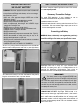
Connecting the Battery
WARNING! Never accidentally short together the positive (+)
and negative (-) battery connections! Doing so will result in
permanent damage to the battery and possible fi re hazard.
SuperTigre ESCs have a unique “ST” type polarized battery
connector as shown here, which is custom-matched to the
connector on SuperTigre LiPo batteries. These plugs are
polarized and cannot accidentally be connected backwards.
IMPORTANT!
The battery must be fully charged BEFORE being
connected to the ESC. The ESC will then
automatically set the low voltage cut-off point based
on the INITIAL voltage of the battery multiplied by 0.67. So, if
the battery is NOT fully charged when connected to the ESC,
the ESC may set a low voltage cut-off that is too low, and may
not be good for your battery. Make sure the battery is fully
charged prior to every use.
LOW VOLTAGE CUT-OFF: SuperTigre ESCs include a low-
voltage cut-off feature that stops motor rotation if the battery’s
voltage drops too low. This protects the battery from damage
due to under-voltage conditions. When the low voltage cut-off
stops motor rotation, it will still supply power to the receiver and
all control surfaces except throttle. You can therefore maintain
control of the aircraft.

8
Setting Up the Brake Function
SuperTigre ESCs include an adjustable brake function. To keep
the factory default brake setting of “off”, skip to the next section.
To turn the brake “on”:
1. With the transmitter power turned off, move the throttle stick
to full position.
2. Turn on the transmitter and connect the fully charged battery
to the ESC.
3. After 5 seconds the motor will beep twice.
4. Move the throttle stick to the minimum position. The motor will
beep twice.
5. Again move the throttle stick to full power. The motor will beep
twice to confi rm the brake is now “on”.
6. Move the throttle stick back to “off”. The motor will now beep four
times, indicating the motor is “armed”. The motor WILL ROTATE
anytime the throttle stick is advanced.
Once the brake is set, it does not require resetting after the ESC
has been switched off.
If the brake had previously been turned on, but you wish to turn
the brake off, repeat the above process. This time the motor will
only beep once with each stick movement, but will beep four
times again at the end to indicate the ESC is armed.
Arming the ESC & Safe-Start Function
If ready to apply power to the motor:
1. Turn the transmitter’s power on.
2. Move the throttle stick to the minimum or brake position
(towards you).
3. Connect a fully charged battery to the ESC. The motor will beep
to indicate the brake setting (once for off, twice for on).
4. Move the throttle stick to full. The motor will again beep once
or twice to indicate the brake setting.
5. Move the throttle stick to “off” or “brake” and the motor will
beep four times. The ESC is now “armed”, and the motor WILL
ROTATE anytime the throttle stick is advanced.
If the ESC does not operate properly or makes a low pitched
beeping sound following the above set-up procedure, disconnect
the battery from the ESC, reverse the throttle setting on the
transmitter and repeat the ESC set-up.
SAFE-START: As a safety precaution to prevent the motor from
rotating when the battery is fi rst connected, you must “arm” the
ESC every time you connect the battery. The propeller will NOT
rotate until the ESC is armed. To arm the ESC, move the throttle
stick to full position, then back to “off” (or “brake”). Now the motor
will rotate anytime the throttle stick is advanced away from
the “off” position! Care must be exercised when near the
model’s propeller!
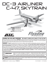
INSTALL PROPELLER AND SPINNER
✰ 1. Put the prop adapter onto the motor shaft. Slide the prop
hub over the adapter.
✰ 2. Install the spinner backplate onto the prop adapter. Put
the propeller onto the prop adapter followed by the prop washer
and prop nut. Thoroughly tighten the prop nut.
✰ 3. Install the spinner cone onto the spinner backplate using
two 2.5mm x 10mm self-tapping screws.

9
GET THE MODEL READY TO FLY
Check the Control Directions
✰ 1. Turn on the transmitter, plug the fl ight battery into the ESC
and center the trims. Note: Whenever the fl ight battery is
connected to the ESC, stay clear of the propeller!
✰ 2. With the transmitter on and fl ight battery still plugged in, check
all the control surfaces to see if they are centered. If necessary,
adjust the clevises on the pushrods to center the control surfaces.
Lower
Throttle Stick
Motor turns off
Advance Throttle Stick
Motor runs full speed
Pull Control
Stick Back
Elevator moves up
Move Control
Stick Right
Right aileron moves up,
left aileron moves down
Move Control
Stick Left
Rudder moves left
If any of the control surfaces respond opposite to what is shown in
the pictures, change the position of the servo reversing switch.
Set the Control Throws
Your Mini NexSTAR EP RxR is set up out of the box to have
the optimum control throws (the distance the control surfaces
move when stick input is given). Programmable radio systems
will allow you to increase or decrease the amount of control
throw to suit for fl ying preference. We do not recommend
increasing the control throws at any time as the model could
become unstable during fl ight and landing. Control throws can
be decreased. However, we suggest only doing this with the
supervision of a fl ight instructor per their recommendation.
The default control throws as the Mini NexSTAR EP is setup from
the factory (assuming all ATVs are set to 100% in programmable
radios) are provided in the table below. It is good practice to
always confi rm control throws prior to fl ying a model for the fi rst
time. This information is also useful if you change the control
throws and wish to return them to the factory set amounts. Note:
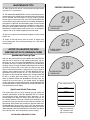
Control throw gauge templates are on page 13.
These are the default control surface throws:
ELEVATOR RUDDER AILERONS
1/2"
[
13mm
]
24°
Up
1/2"
[
13mm
]
24°
Down
5/8"
[
16mm
]
25°
Right
5/8"
[
16mm
]
25°
Left
13/16"
[
21mm
]
30°
Up
13/16"
[
21mm
]
30°
Down

10
Balance the Model (C.G.)
DO NOT DISREGARD THIS STEP! This important step
is also referred to as “checking the C.G.” (center of gravity).
Simply stated, the center of gravity is the point at which the
model balances when lifted under the wing. If the C.G. is
too far forward, the model will be “nose-heavy” and could be
diffi cult to takeoff and land and lose some of its self-correcting
tendencies. If the C.G. is too far aft, the model will be “tail-
heavy” and the controls may be too sensitive, making the
model too diffi cult to control—especially for an inexperienced
pilot! Follow the instructions to balance the model correctly,
thus giving you the greatest chances for success!
✰ 1. Make certain the model is in “Ready-to-fl y” condition with all
components mounted and installed (propeller, spinner, receiver,
fl ight battery, etc.)
✰ 2. Mount the wing to the fuselage with the wing bolt. Lift the
model on both sides of the fuselage with your fi ngertips on the dots
on the bottom of the wing. You can also use a C.G. Machine which
is a useful tool designed for setting the C.G. of model planes.
✰ 3. If the fuselage is level when lifting the model with your
fi ngers on the dots, the C.G. is correct. Proceed to the checklist
in the following section. If you cannot fi nd a spot between the two
lines where the airplane balances, then either one of the following
will happen: If the tail drops when lifting the model, the plane is
tail heavy and the fl ight battery will need to be moved forward on
the battery tray. If the nose drops, the plane is nose heavy and
the fl ight battery will need to be moved back on the battery tray.
When you have determined where the fl ight battery needs to be
positioned in order to balance the plane on the dots, make a mark
somewhere on the battery tray so you will have a reference point
when installing the battery for fl ight.
PREFLIGHT
Identify Your Model
No matter if you fl y at an AMA sanctioned R/C club site or if you
fl y somewhere on your own, you should always have your name,
address, telephone number and AMA number on or inside your
model. It is required at all AMA R/C club fl ying sites and AMA
sanctioned fl ying events. Fill out the identifi cation tag on page 19
and place it on or inside your model.
Charge the Batteries
Follow the battery charging instructions that came with your radio
control system to charge the transmitter battery. You should always
charge your transmitter battery the night before you go fl ying, and
at other times as recommended by the radio manufacturer.
CAUTION: Unless the instructions that came with your radio
system state differently, the initial charge on new transmitter
batteries should be done for 15 hours using the slow-charger
that came with the radio system. This will “condition” the
battery so that the next charge may be done using the fast-
charger of your choice. If the initial charge is done with a fast-
charger the battery may not reach its full capacity and you may
be fl ying with a battery that is only partially charged.
MOTOR SAFETY PRECAUTIONS
Failure to follow these safety precautions may result in
severe injury to yourself and others.
✰ Get help from an experienced pilot when learning to
operate motors.
✰ Use safety glasses when running motors.
✰ Do not run the motor in an area of loose gravel or sand; the
propeller may throw such material in your face or eyes.
✰ Keep your face and body as well as all spectators away from
the plane of rotation of the propeller as you run the motor.
✰ Keep these items away from the prop: loose clothing, shirt
sleeves, ties, scarfs, long hair or loose objects such as pencils
or screwdrivers that may fall out of shirt or jacket pockets into
the prop.
✰ The motor gets hot! Do not touch it during or right
after operation.
✰ Do not throw anything into the propeller of a running motor.

11
AMA SAFETY CODE (EXCERPTS)
Read and abide by the following excerpts from the Academy of
Model Aeronautics Safety Code. For the complete Safety Code
refer to Model Aviation magazine, the AMA web site or the Code
that came with your AMA license.
General
1) I will not fl y my model aircraft in sanctioned events, air shows,
or model fl ying demonstrations until it has been proven to
be airworthy by having been previously, successfully fl ight
tested.
2) I will not fl y my model aircraft higher than approximately 400
feet within 3 miles of an airport without notifying the airport
operator. I will give right-of-way and avoid fl ying in the proximity
of full-scale aircraft. Where necessary, an observer shall be
utilized to supervise fl ying to avoid having models fl y in the
proximity of full-scale aircraft.
3) Where established, I will abide by the safety rules for the fl ying
site I use, and I will not willfully and deliberately fl y my models
in a careless, reckless and/or dangerous manner.
5) I will not fl y my model unless it is identifi ed with my name and
address or AMA number, on or in the model. Note: This does
not apply to models while being fl own indoors.
7) I will not operate models with pyrotechnics (any device that
explodes, burns, or propels a projectile of any kind).
Radio Control
1) I will have completed a successful radio equipment ground
check before the fi rst fl ight of a new or repaired model.
2) I will not fl y my model aircraft in the presence of spectators until
I become a qualifi ed fl ier, unless assisted by an experienced
helper.
3) At all fl ying sites a straight or curved line(s) must be established
in front of which all fl ying takes place with the other side for
spectators. Only personnel involved with fl ying the aircraft are
allowed at or in the front of the fl ight line. Intentional fl ying
behind the fl ight line is prohibited.
4) I will operate my model using only radio control frequencies
currently allowed by the Federal Communications Commission.
5) I will not knowingly operate my model within three miles of any
pre-existing fl ying site except in accordance with the frequency
sharing agreement listed [in the complete AMA Safety Code].
9) Under no circumstances may a pilot or other person touch
a powered model in fl ight; nor should any part of the model
other than the landing gear, intentionally touch the ground,
except while landing.
FINAL CHECKLIST
Now it’s time to do a fi nal check before taking the model to the
fi eld. These checks are best done in the peace and comfort of
your own shop, so take the time now to make certain your model
is ready.
✰ 1. Check the C.G. according to the procedure provided in
the manual.
✰ 2. Be certain the battery and receiver are securely mounted
in the fuse.
✰ 3. Confi rm that the wing bolt is properly tightened.
✰ 4. Make sure all hinges are securely glued in place.
✰ 5. Confi rm that all controls operate in the correct direction
and the throws are set up according to the manual.
✰ 6. Make sure any servo extension cords you may have used do
not interfere with other systems (servo arms, pushrods, etc.).
✰ 7. Tighten the propeller nut and spinner.
✰ 8. Place your name, address, AMA number and telephone
number on or inside your model.
✰ 9. If you wish to photograph your model, do so before your
fi rst fl ight.
✰ 10. Confi rm that your fl ight battery(s) is/are fully charged.
FLIGHT PREPARATION
The Hobbico Mini NexSTAR EP has many features that make
learning to fl y R/C an easier experience, but the help from an
instructor is invaluable. An instructor is going to be able to inspect
your airplane to make sure everything is working correctly and
he will also be able to give you a few tips and comments on
how to improve your fl ying. Also, make sure you fl y at an AMA
sanctioned fl ying fi eld.
Flight preparation is to be done at the fl ying fi eld.
Check the Frequency (FM & PCM Radio Systems)
IMPORTANT: Your radio control system transmits a signal on
a certain frequency. Be certain you know what the frequency
is. This is expressed as a two-digit number (42, 56, etc.), and
can be found on the container the transmitter came in and
is also located on the transmitter. There are several different
frequencies, but there is still a chance that someone else at the
fl ying fi eld may be on the same frequency as you. If you turn on
your transmitter while that person is fl ying, a crash will result.
NEVER turn on your transmitter until you have permission from
your instructor, and until you have possession of the frequency
clip used for frequency control at the fl ying site.
Check the Controls
Be certain your fl ight instructor performs these following checks
with you.
✰ 1. Get the frequency clip from the frequency control board at
your fl ying site.
✰ 2. Connect the aileron servo leads to the Y-harness and
mount the wing to the fuselage with the wing bolt.

12
✰ 3. Turn on the transmitter and plug in the fl ight battery. One at
a time, operate each control on the airplane using the sticks
on the transmitter. Make certain each control is responding
correctly. This must be done before every fl ight. There are
several types of malfunctions that can be discovered by
performing this elementary task, thus saving your model!
Range Check the Radio
Ground check the operational range of your radio before the fi rst
fl ight of the day. With the transmitter antenna collapsed and the
receiver and transmitter on (refer to your radio manual if using
a 2.4GHz system), you should be able to walk at least 100 feet
away from the model and still have control. Have an assistant
stand by your model and, while you work the controls, tell you
what the control surfaces are doing. Repeat this test with the
motor running at various speeds with an assistant holding the
model, using hand signals to show you what is happening. If the
control surfaces do not respond correctly, do not fl y! Find and
correct the problem fi rst. Look for loose servo connections or
broken wires or a damaged receiver crystal from a previous crash.
If you cannot fi nd the problem, ask an experienced modeler for
assistance or call Product Support.
FLYING
Do not attempt to fl y by yourself.
IMPORTANT: Be aware of your proximity to R/C club sites. If
there is an R/C site within six miles of where you are fl ying, and
if you are operating your model on the same frequency at the
same time as somebody else, there is a strong possibility that
one or both models will crash due to radio interference. There
is great potential for an out-of-control model to cause property
damage and/or severe personal injury. We strongly urge you to
fl y at a R/C club site where frequency control is in effect so you
can be assured you will be the only one fl ying on your channel.
Taxiing
Remember, it is assumed that your instructor is operating the
model for you.
Before the model is ready for takeoff, it must fi rst be set up to roll
straight down the runway. Place the plane on the runway and, if
your fl ying fi eld permits, stand behind the model. Advance the
throttle just enough to allow the model to roll. If the model does
not roll straight down the runway, adjust the rudder trim on your
transmitter until it does. Note: Crosswinds may affect the direction
the model rolls, so this test should be done in calm conditions,
or with the model facing directly into the wind. With the plane
now taxiing straight, adjust the position of the rudder pushrod in
the adjustable clevis to return the rudder to the neutral position
if necessary.
Takeoff
If possible, takeoff directly into the wind. If you are experienced,
taking off in a crosswind is permissible (and sometimes
necessary—depending upon the prevailing wind conditions and
runway heading). Taking off into the wind will help the model
roll straight and also reduces ground speed for takeoff. Taxi the
model onto the runway or have an assistant carry it out and set
it down, pointing down the runway into the wind. When ready,
gradually advance the throttle while simultaneously using the
left stick (rudder/nose wheel) to steer the model. Gain as much
speed as the runway and fl ying site will practically allow before
gently applying up elevator lifting the model into the air. Be ready
to make immediate corrections with the ailerons to keep the
wings level, and be smooth on the elevator stick, allowing the
model to establish a gentle climb to a safe altitude before making
the fi rst turn (away from yourself). Do not “yank” back the elevator
stick forcing the plane into too steep of a climb. This could cause
the model to quit fl ying and stall. The Hobbico Mini NexSTAR
EP includes a powerful brushless motor that will safely pull your
airplane up at a 45° angle.
Flight
Once airborne, maintain a steady climb and make the initial turn
away from the runway. When at a comfortable, safe altitude,
throttle back to slow the model, thus giving you time to think and
react. The Hobbico Mini NexSTAR EP should fl y well at half or
slightly less than half throttle. Adjust the trims so the plane fl ies
straight and level with the sticks centered. After fl ying around for
a while, and while still at a safe altitude with plenty of battery
charge remaining, practice slow fl ight and execute practice
landing approaches by reducing the throttle further to see how the
model handles when coming in to land. Add power to see how the
model climbs as well. Continue to fl y around while learning how
the model responds. Mind your remaining battery charge, but use
this fi rst fl ight to become familiar with the model before landing.
Landing
When ready to land, reduce the power while fl ying downwind just
before making the 180° turn toward the runway. Allow the nose
of the model to pitch downward to gradually bleed off altitude.
Continue to lose altitude, but maintain airspeed by keeping the
nose down while turning. Apply up elevator to level the plane
when it reaches the end of the runway and is about fi ve to ten
feet off the ground. If the model is too far away, carefully add
a small amount of power to fl y the model closer. If going too
fast, smoothly advance the throttle and allow the model to gain
airspeed. Then, apply elevator to climb out and go around to make
another attempt. When fi nally ready to touch down, continue to
apply up elevator, but not so much that the airplane will climb.
Continue to apply up elevator while the plane descends until it
gently touches down.
The Mini NexSTAR EP has been designed to make landing
approaches short and easy. The Speed Brake Training Flaps excel
at maintaining fl ying speed even in steep dives, and when the
airplane is leveled-out, they also help to increase lift. You can also
make a long landing approach and use throttle to keep the airplane
fl ying at a very low speed until you reach the runway threshold
where you should cut the throttle for the airplane to land.
After you have landed and disconnected the fl ight battery, adjust
the pushrods on the ailerons, elevator and rudder as necessary
so the trim levers on the transmitter may be returned to center.
This will not be required on any of the controls that did not need
trim adjustments.

13
MAINTENANCE TIPS
✰ After fl ying for the day, be sure to remove the fl ight battery
and store it in a safe location.
✰ The Hobbico Mini NexSTAR EP is factory-covered with iron-on
model covering fi lm. Should repairs ever be required, the covering
can be patched with new pieces of iron-on covering. Among
several types of covering that will work, Top Flite MonoKote fi lm
may be used to make repair patches to this model. MonoKote is
packaged in six-foot rolls, but some hobby shops also sell it by the
foot. If only a small piece of covering is needed for a minor patch,
perhaps a fellow modeler would give you some. The covering is
applied with a model airplane covering iron, but in an emergency
a regular iron set to a lower temperature could be used.
✰ Check all screws that hold the wings together, tail bolts, motor
screws, etc.
✰ Check all the high-stress areas for cracks or fatigue such
as the landing gear area, the wing mounting area, stab and fi n
mounting area.
AFTER YOU MASTER THE MINI
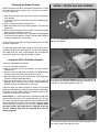
NEXSTAR EP IN ITS ORIGINAL FORM
Speedbrakes Training Flaps
After you feel comfortable fl ying the Hobbico Mini NexSTAR EP
and you want to improve its high speed performance, the fi rst
thing you can do is to remove the SpeedBrakes Training Flaps.
To remove the fl aps, carefully peel them from the underside of
the wing. Gently warming the double-sided tape used to secure
the fl aps to the wing with a hair dryer on LOW heat will allow
them to come off more easily. If applying heat, take care not to
allow the heat to deform the fl aps. The Mini NexSTAR EP was
optimized to fl y with the fl aps on, so if you remove them, you
will have to re-trim the elevator. Without fl aps, the Mini NexSTAR
EP will try to pitch down (nose down) until you re-trim it with
some up elevator. Without the SpeedBrakes Training Flaps, the
airplane will fl y much faster at any throttle setting and longer
landing approaches will be needed. Also, the Mini NexSTAR EP
will not slow down as quickly when the nose is pointed down and
stall speed will increase slightly.
SpinControl Airfoil Extensions
The second thing you can do to improve the high speed and
aerobatic performance of the Mini NexSTAR EP is to remove
the SpinControl Airfoil Extensions.These extensions at the
leading edge of the wings are held in place with tape that can
be carefully removed. Once you remove these extensions, you
will need to re-trim your elevator to align it with the stabilizer. The
SpinControl Airfoil Extensions produce the opposite effect than
the SpeedBrakes Training Flaps in pitch, so if you remove both,
the net pitch effect would be almost non existent. After you remove
these extensions, the Mini NexSTAR EP will be faster and able to
spin and snap. Also, the stall speed will increase slightly.
GOOD LUCK AND GREAT FLYING!
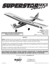
24°
ELEVATOR CONTROL
THROW GAUGE
25°
RUDDER CONTROL
THROW GAUGE
30°
AILERON CONTROL
THROW GAUGE
CONTROL THROW GAUGES
This model belongs to:
Name
Address
City, State Zip
Phone number
AMA number
Copy (or cut out) this
tag, complete it and
place in your model.

14
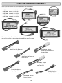
OTHER ITEMS AVAILABLE FROM HOBBICO
To adapt your SuperTigre ESC to batteries having different types of connectors,
see your local retailer for these SuperTigre adapters to meet your needs:
SuperTigre offers several sizes of LiPo batteries to suit various needs,
which can be found at most hobby retailers:
SUPP1010 640mAh, 11.1V LiPo
SUPP1020 910mAh, 11.1V LiPo
SUPP1030 1250mAh, 11.1V LiPo
SUPP1050 1500mAh, 11.1V LiPo
SUPP1060 1800mAh, 11.1V LiPo
SUPP1070 2100mAh, 11.1V LiPo
SUPM0010...Adapter
SuperTigre LiPo Battery to
Deans
®
Ultra Plug
®
Female
SUPM0070...Charge lead
Banana Plugs to
SuperTigre LiPo Battery
SUPM0060...Adapter
Standard Female to
SuperTigre ESC
SUPM0050...Adapter
Deans Micro to
SuperTigre ESC
SUPM0040...Adapter
Deans Ultra Male to
SuperTigre ESC
SUPM0030...Adapter
SuperTigre LiPo Battery to
Standard Male
SUPM0020...Adapter
SuperTigre LiPo Battery to
Deans Micro

15
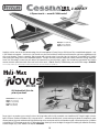
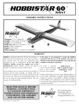
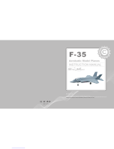
Simplicity, realism, state-of-the-art radio technology...they all come together in Flyzone’s Cessna 182 Skylane. Fully assembled and equipped — only
4 “AA” batteries are required — the Cessna is just minutes away from the first takeoff. An ABS cowl and wheel pants and factory-applied decals top
off its scale-like looks. Thanks to a powerful, 380-size motor and 4-channel control, it even flies like a full-size plane! The included Tactic™ 2.4GHz
radio system offers today’s best in safe, dependable operation. The signal constantly switches frequencies to make interference virtually impossible.
Secure Link Technology™ ensures that your receiver will respond only to your transmitter’s signals. Also included are a preinstalled Tactic 2.4GHz
receiver; electronic speed control with auto cut-off and 3 micro servos; 1100mAh ElectriFly™ NiMH battery pack; and 12V DC charger. HCAA2505
Cessna 182, Skylane, emblems, logos, and body designs are trademarks of Textron Innovations Inc. and are used under license by Hobbico, Inc."
Day or night, in any weather, you can enjoy first-class heli flying indoors with the fully assembled, nano-sized Novus CX. Though it weighs a feather-
light 1.85 ounces, the Novus CX delivers full, 4-channel control — and features durable plastic, counter-rotating main blades for exceptionally stable
hovering and easy forwards and backwards flight. Ball bearings in the swash plate and main shaft produce smooth, efficient performance. In addition
to the model, this RTF package comes with a 2.4GHz radio system (featuring a convenient digital servo/gyro/ESC module) plus 400mAh LiPo battery
and wall charger. Only 8 “AA” batteries are required. HMXE0803
Wingspan: 35 in (890 mm)
Length: 27.5 in (700 mm)
Requires: 4 “AA” batteries
Rotor Diameter: 6.9 in (175 mm)
Weight: 1.85 oz (52.6 g)
Height: 5.1 in (130 mm)
Length: 8 in (205 mm)
Width: 1.6 in (40 mm)
™
A Flyzone favorite — now with 2.4GHz control!
Full-featured heli fits in the
palm of your hand!
2.4GHz RTF
2.4GHz RTF
®
™

®
-
 1
1
-
 2
2
-
 3
3
-
 4
4
-
 5
5
-
 6
6
-
 7
7
-
 8
8
-
 9
9
-
 10
10
-
 11
11
-
 12
12
-
 13
13
-
 14
14
-
 15
15
-
 16
16


Hobbico NexSTAR mini EP RxR Assembly Manual And Use And Care
- Category
- Toys & accessories
- Type
- Assembly Manual And Use And Care
Ask a question and I''ll find the answer in the document
Finding information in a document is now easier with AI
Related papers
-
 Hobbico Zoom Pilot Action Series User manual
-
 Hobbico FlyZone Park Pilot User manual
-
 Hobbico Sky Pilot User manual
-
 Hobbico NexSTAR EP User manual
-
 Hobbico Flyzone DC-3 Airliner User manual
-
 Hobbico HCAA62 series User manual
-
 Hobbico Hobbistar 60 Select Assembly Instructions Manual
-
Flyzone L-39 User manual
-
 Hobbico Nexstar select User manual
-
 Hobbico FLYZONE ME 109 Assembly


Other documents
-
 Tinkertoy 01531 User manual
-
 H-KING Sky Sword User manual
-
COX Extra 300 User manual
-
 StarMax F-35 User manual
-
Flyzone Cessna 182 Skylane User manual
-
Tower Hobbies Tower Trainer 40 Ready-to-Fly User manual
-
 WattAge P-51 MUSTANG EP RTF Operating Instructions Manual
-
HobbyKing SKIPPER User manual
-
 Art-Tech ASK-21 User manual
-


