Page is loading ...

Appli-Mate (RAST2.5 Power) Manual Terminator
Doc. No: TM-622030000 Release Date: 12-19-07 UNCONTROLLED COPY Page 1 of 16
Revision: D Revision Date: 10-10-16
APPLI-MATE (RAST2.5 Power)
MANUAL TERMINATOR
Operation Manual
Description
Operation
Maintenance

Appli-Mate (RAST2.5 Power) Manual Terminator
Doc. No: TM-622030000 Release Date: 12-19-07 UNCONTROLLED COPY Page 2 of 16
Revision: D Revision Date: 10-10-16
WARNING
NEVER OPERATE, SERVICE, INSTALL OR ADJUST THIS MACHINE
WITHOUT PROPER INSTRUCTION AND WITHOUT FIRST
READING AND UNDERSTANDING THE INSTRUCTIONS IN
THIS MANUAL.
WORK SAFELY AT ALL TIMES
For Service, Contact Your
Local Molex Sales Office
Molex Application Tooling Group
2200 Wellington Court
Lisle, Illinois 60532
Tel: 630-969-4550
Fax: 630-505-0049

Appli-Mate (RAST2.5 Power) Manual Terminator
Doc. No: TM-622030000 Release Date: 12-19-07 UNCONTROLLED COPY Page 3 of 16
Revision: D Revision Date: 10-10-16
Table of Contents
SECTION
1. General Description, Installation, and Operation
2. Maintenance, Perishable Parts, Spare Parts and Troubleshooting
3. Parts List and Assembly Drawings, Connector Series Chart

Appli-Mate (RAST2.5 Power) Manual Terminator
Doc. No: TM-622030000 Release Date: 12-19-07 UNCONTROLLED COPY Page 4 of 16
Revision: D Revision Date: 10-10-16
Section 1
General Description
1.1 Description
1.2 Features
1.3 Technical Specifications
1.4 Delivery Check
1.5 Installation
1.6 Setup
1.7 Operation

Appli-Mate (RAST2.5 Power) Manual Terminator
Doc. No: TM-622030000 Release Date: 12-19-07 UNCONTROLLED COPY Page 5 of 16
Revision: D Revision Date: 10-10-16
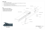
Figure 1-1
HOUSING LOAD
PLATFORM
CONNECTOR
NEST
WIRE
GUIDES
PRESS FRAME
MOUNTING HOLES
PRESS
FRAME
UPPER
TOOLING
ADAPTER
BLOCK
PRESS
LEVER
Principal Mechanical parts of the Appli-Mate (RAST2.5 Power) Terminator 62203-0000

Appli-Mate (RAST2.5 Power) Manual Terminator
Doc. No: TM-622030000 Release Date: 12-19-07 UNCONTROLLED COPY Page 6 of 16
Revision: D Revision Date: 10-10-16
General Descrition
1.1. Description
The 62203-0000 Appli-Mate (RAST2.5 Power)
Manual Terminator, complete with arbor press, is
designed to terminate the Appli-Mate (RAST2.5
Power) female connector series (91627 and 91791)
onto discrete wire (0.50mm² or 0.75mm²). The
connectors are supplied as a stack. The stack is a
series of connectors attached by tabs that are cut
apart during termination. The terminator will
accommodate circuit size 2 through 12. An operator
loads a connector into the nest, inserts the wires into
position, and cycles the press. When the cycle is
complete, the operator removes the harness. This
terminator is ideally suited for low to medium volume
production.
1.2. Features
Bench top operation.
Manual operation, no air or electricity required.
Wire tension adjustment
Quick release lever for harness removal
Adjustable press lever for operator comfort
1.3. Technical Specification
Dimensions
Width: 210mm (8.3")
Depth: 136mm (5.4") without connector support
Depth: 485mm (19.1") with connector support
Height: 525mm (20.7")
Weight
18.1kg (40lbs)
Rate
Approximately 450 discrete wires per hour
depending on operator skill.
1.4. Delivery Check
Carefully remove the Terminator from its shipping
container and determine that the following items
are included in the package.
Order No. Qty.
62203-0000 Appli-Mate Manual Terminator
(RAST2.5 Power) 1
62201-7414 Housing Load Platform 1
TM-622030000 Instruction Manual 1
1.5. Installation
Set the press on a bench of suitable height and
capable of supporting at least 70 kg (155 Lbs).
Using the two (2) M4 X 12 FHCS supplied with the
press, mount the Housing Load Platform to the
press as shown in Figure 1-1. (Also see the
assembly drawing in Section 3.) There are two (2)
clearance holes in the Press Frame (see Figure 1-1)
for M8 or 5/16 in. screws, if it is desired to bolt the
press to the bench. Make sure there is adequate
room around the press for the operator to load
connectors and to store wires and finished
harnesses. Make certain there is adequate lighting.
1.6. Setup
Termination Height (Figure 1-1 and 1-2)
In order to insure the connector top half is
correctly seated in the lower half and that the
wires are correctly terminated, it may necessary
to adjust the termination height. This is done as
follows:
1. To adjust the termination height, loosen the
three (3) socket head cap screws that lock the
adaptor block to the press frame.
2. To decrease the termination height (the height
of the connector after termination) turn the
height adjusting knob counterclockwise. To
increase the height, turn the knob clockwise.
3. When the desired height is set, tighten the
locking screws. The height of the terminated
connector should be 15.10mm ± 0.10 (0.594” ±
.004).

Appli-Mate (RAST2.5 Power) Manual Terminator
Doc. No: TM-622030000 Release Date: 12-19-07 UNCONTROLLED COPY Page 7 of 16
Revision: D Revision Date: 10-10-16
Figure 1
-
2
ADAPTER BLOCK AND SCREWS
ADAPTER
BLOCK
ADAPTER
BLOCK
LOCKING
SCREWS
Figure 1
-
3
SETTING THE CONNECTOR GUIDE
(MANY PARTS NOT SHOWN FOR CLARITY)
LOCKING
SCREW
FIXED GUIDE
BLOCK
CONNECTOR
STACK
CONNECTOR
SUPPORT
ADUSTUSTABLE
GUIDE BLOCK
Figure 1
-
4
WIRE TENSION ADJUSTMENT
WIRE
GUIDES (12)
STOP SCREW
RELEASE
LEVER
Adjusting for Connector Size
The Appli-Mate (RAST2.5 Power) connectors are
available in circuit sizes 2 through 12. The guides
must be adjusted to fit the desired connector circuit
size. That is done as follows:
1. Loosen or remove the locking screw for the
adjustable guide block and position the guide to fit
the desired connector stack. Place the stack on
the connector support and slide it forward until it is
between the fixed and the adjustable guide blocks.
See Figure 1-3.
2. Replace the locking screw if it was removed but do
not tighten.
3. Slide the adjustable guide block toward the fixed
guide block until the connector stack slides
between the guides with minimum clearance.
4. Tighten the adjustable guide block locking
screw.
Adjusting the Wire Tension
It is necessary to make an adjustment to the wire
stop when changing from one wire size to another.
Refer to Figure 1-4.
1. Turn the stop screw clockwise to decrease the
tension or counterclockwise to increase the
tension applied to the wire. Adjust the tension so
the wire can be pushed through the guides, into
the connector, and held firmly in place upon
release.

Appli-Mate (RAST2.5 Power) Manual Terminator
Doc. No: TM-622030000 Release Date: 12-19-07 UNCONTROLLED COPY Page 8 of 16
Revision: D Revision Date: 10-10-16
Figure 1
-
7
LOADING CONNECTOR STACKS
HOUSING
LOCATOR
F
igure 1
-
5
HOUSING (CONNECTOR) LOCATOR
HOUSING
POSITIONER
HOUSING
POSITIONER
AGAINST THE
CONNECTOR
Figure 1
-
6
CONNECTOR IN POSITION
WIRE GUIDES
(12)
MOVE
HOUSING
LOCATOR ALL
THE WAY TO
THE RIGHT
1.7. Operation
1. Load a stack of connectors between the guide
blocks as shown in Figure 1-3.
2. Pull the knob on the housing locator and move it
all the way to the left. See Figure 1-5.
3. Move housing positioner towards the stack of
connectors. It should snap into place.
4. Place the index and middle fingers on top of the
connector stack. Applying a slight downward
pressure, slide the connector stack forward until
the connector “snaps” into place. See Figure 1-6.
5. Push the knob on the housing locator all the way
to the right.
6. Load the wires individually by inserting them
through the wire guides into the holes of the
connector and up against the stop.
7. Move housing positioner away from the connector.
WARNING: If the positioner is not moved, the
press ram will hit the positioner and damage it.
8. When all wires are loaded, cycle the press by
pulling the press lever to the full down position.
This will press the two halves of the connector
together terminating the wires and latching the
connector halves together. This will also cut the
terminated connector from the stack.
9. Return the press lever to the full up position.
10. Remove the terminated connector assembly by
pressing down on the wire release lever and
sliding the assembly out to the right. See Figure
1-4.
NOTE: The lower housing must be removed when
loading the first stack of connectors into the press. To
attach another stack, insert the upper housing at the
end of the first stack into the lower housing of the new
stack. See Figure 1-7.

Appli-Mate (RAST2.5 Power) Manual Terminator
Doc. No: ATS-622030000 Release Date: 12-19-07 UNCONTROLLED COPY Page 9 of 16
Revision: A Revision Date: 12-19-07
Section 2
Set-Up and Operation
2.1. Maintenance
2.2. Perishable Parts
2.3. Spare Parts
2.4. Troubleshooting

Appli-Mate (RAST2.5 Power) Manual Terminator
Doc. No: TM-622030000 Release Date: 12-19-07 UNCONTROLLED COPY Page 10 of 16
Revision: D Revision Date: 10-10-16
2.1 Maintenance
(See Chart 2.1 for maintenance scheduling,)
Cleaning
The APPLI-MATE (RAST2.5 Power) Manual Terminator should be cleaned at least once a day with a soft
brush to remove dust and debris.
Lubrication
The press requires regular lubrication on a monthly basis. Place a small amount of lubricant with Teflon,
such as Permatex “Superlube”, on the sliding surfaces.
An example of a maintenance chart is shown below. Copy and use this chart to track the maintenance of your
Terminator or use this as a template to create you own schedule or use your company’s standard chart, if
applicable.
Preventive Maintenance Chart
Daily: Clean. See Section 2.1.
As Required: Lubricate. See Section 2.1.
CHECK SHEET MONTH YEAR _________
Week
Daily
Cycles
Daily
Clean
Days of the Week
Solution
MON TUE WED THU FRI SAT
SUN
1
2
3
4
Cleaning
Reapply grease
Reapply oil
Soft Brush Industrial
Degreaser
Inspect all tooling, feed
fingers etc. for wear
Replace if signs of wear.
Schedule should be adjusted up or down depending on usage. Molex recommends that a log of preventive
maintenance be kept with the press.
CAUTION:
Using compressed air to clean the Terminator is not recommended as
debris could become jammed in the tooling and/or come flying out at the operator.

Appli-Mate (RAST2.5 Power) Manual Terminator
Doc. No: TM-622030000 Release Date: 12-19-07 UNCONTROLLED COPY Page 11 of 16
Revision: D Revision Date: 10-10-16
2.2 Perishable Parts
Customers are responsible for maintaining the APPLI-MATE (RAST2.5 Power) Manual Terminator.
Perishable parts are those parts that come in contact with the product and will wear out over time. Molex
recommends that all customers keep at least one set of the perishable tool kits in stock at all times. This
will reduce the amount of production down time. These parts are identified in the Parts List in Section 3.
2.3 Spare Parts
Customers are responsible for maintaining the APPLI-MATE (RAST2.5 Power) Manual Terminator. Spare
parts are available. Moving and functioning parts can be damaged or wear out over time and will require
replacement. Molex recommends that the customer keep some or all of them in stock to reduce production
down time. These parts are identified in the Parts List. See Section 3.
2.4. Troubleshooting
Symptom Cause Solution
Terminat
ion height
not within specification
Termination tooling height not set correctly
Readjust termination height.
See Section 1.6: Termination Height.
Wire not sliding
easily
into position
Wire guide spring tension set too high
Readjust the spring tension.
See Section 1.6: Adjusting the Wire
Tension.
There is debris in the openings
Check the tooling and the connector
for debris and clean as required.
Wire not staying in
position after loaded
Wire guide spring tension set too low
Readjust the spring tension
.
See Section 1.6: Adjusting the Wire
Tension.

Appli-Mate (RAST2.5 Power) Manual Terminator
Doc. No: TM-622030000 Release Date: 12-19-07 UNCONTROLLED COPY Page 12 of 16
Revision: D Revision Date: 10-10-16
Section 3
3.1. Parts Lists and Assembly Drawings
3.2. Connector Series Chart

Appli-Mate (RAST2.5 Power) Manual Terminator
Doc. No: TM-622030000 Release Date: 12-19-07 UNCONTROLLED COPY Page 13 of 16
Revision: D Revision Date: 10-10-16
3.1 Parts List and Assembly Drawings (See Figure 3-1)
Appli
-
Mate (
RAST2.5
Power) 62203
-
0000
Item
No.
Order
No
.
Engineering No.
Description
Quantity
Perishable Tooling
1
62
300
-
5913
62
300
-
5913
Termination Blade
1
-
PP
2
6220
3
-
0016
6220
3
-
0016
Carrier Cutoff Blade
1
-
PP
Other Components
3
62201
-
7412
62201
-
7412
Mounting Base
1
4
62201
-
7414
62201
-
7414
Housing Load P
latform
1
5
62201
-
7420
62201
-
7420
Shaft
-
Ram
1
6
62201
-
7423
62201
-
7423
Adapter
-
Front Head
1
7
6220
3
-
00
25
62
203
-
00
25
Ram Guard
1
8
62201
-
7426
62201
-
7426
Molex Nameplate
1
9
62201
-
7428
62201
-
7428
Locator Spacer
1
10
62201
-
7523
62201
-
7523
Guard Angle
1
11
62203
-
0001
62203
-
0001
Locator
-
Housing
1
12
62203
-
0002
62203
-
0002
Ramp
-
Housing
1
13
62203
-
0003
62203
-
0003
Guide
-
Left Housing
1
14
62203
-
0004
62203
-
0004
Guide
-
Right Housing
1
15
62203
-
0005
62203
-
0005
Holder
-
Wire Guide
1
16
62203
-
0006
62203
-
0006
Guide
-
Wire
12
-
RSP
17
62203
-
0007
62203
-
0007
Cover
-
Guide Front
1
18
62203
-
0008
62203
-
0008
Shaft
-
Pivot
1
19
62203
-
0009
62203
-
0009
Release Lever
1
20
62203
-
0011
62203
-
0011
Base
-
Tool
1
21
62203
-
0013
62203
-
0013
Hold
-
Down Spring
1
22
62203
-
0015
62203
-
0015
Positioner
-
Housing
1
23
62203
-
0
017
62203
-
0017
Blade
-
Front Locator
1
24
62203
-
0018
62203
-
0018
Blade
-
Cutoff Support
1
25
62203
-
0019
62203
-
0019
Block
-
Ram
1
26
62203
-
0021
62203
-
0021
Guide
-
Top Wire
1
27
63600
-
0937
63600
-
0937
Slide Knob
1
28
63600
-
0939
63600
-
0939
Wire Guide Spring
12
-
RSP
29
63600
-
1263
63600
-
1263
M5 Ball Plunger
1
30
63600
-
1533
63600
-
1533
M5 Hex Nut
1
31
63600
-
1937
63600
-
1937
Shoulder Screw
2
32
69808
-
1204
69808
-
1204
M8
Fender Washer
2
Frame
33
63600
-
0942
63600
-
0942
Press
-
Toggle
1
Hardware
34
N/A
N/A
M
3
by
6
Long SHCS
3**
35
N/A
N/A
M
3
by
8
Long SHCS
2**
36
N/A
N/A
M
3
by
12
Long
F
HCS
1**
37
N/A
N/A
M
3
by
12
Long SHCS
2**
38
N/A
N/A
M
3
by
14
Long SHCS
2**

Appli-Mate (RAST2.5 Power) Manual Terminator
Doc. No: TM-622030000 Release Date: 12-19-07 UNCONTROLLED COPY Page 14 of 16
Revision: D Revision Date: 10-10-16
Appli
-
Mate (
RAST2.5
Power) 62203
-
0000
39
N/A
N/A
M
3
by
16
Long SHCS
6**
40
N/A
N/A
M
4
by
12
Long
F
HCS
4**
41
N/A
N/A
M
4
by
25
Long
S
HCS
4**
42
N/A
N/A
M5 by
6
Long S
SS
1
**
43
N/A
N
/A
M5 by
12
Long S
SS
1**
44
N/A
N/A
M5 by 20 Long SHCS
4
**
45
N/A
N/A
M8 by
16
Long
F
HCS
1**
46
N/A
N/A
M8 by
30
Long SHCS
3
**
47
N/A
N/A
M8 by
40
Long
F
HCS
1
**
48
N/A
N/A
M8 by 4
0
Long SHCS
3
**
49
N/A
N/A
M8 by 45 Long SHCS
1**
50
N/A
N/A
M3 Flat Washer
1**
51
N/
A
N/A
M
4
Flat Washer
1**
52
N/A
N/A
M
8
Hex Nut Full
1**
53
N/A
N/A
3mm by 10 Long Dowel Pin
4**
54
N/A
N/A
3mm by 12 Long Dowel Pin
4**
55
N/A
N/A
5mm by 12 Long Dowel Pin
1**
56
N/A
N/A
5mm by 16 Long Dowel Pin
2**
** Available from an industrial supply compa
ny such as MSC (1
-
800
-
645
-
7270).
The following pages contain the APPLI-MATE (RAST2.5 Power) Manual Terminator Parts Lists and
Assembly Drawings. The following definitons may help the reader better understand and use this material.
1. The “RSP” appearing at the end of the description column means this item is a Recommended Spare
Part. See Section 2.3 for description of “recommended spare part”.
2. The “PP” appearing at the end of the description column means this item is a Perishable Part. See
Section 2.2 for description of “perishable part”.
3. The termination blade supplied with the Manual Terminator will terminate all circuit sizes of RAST2.5
Power connectors with open end walls and any combination of inner ribs and/or latches. For
connectors with closed end wall(s) the specific circuit size blade must be ordered:
Closed
-
End Wall Termination Blades
Item No.
Order No.
Engineering No.
Description
Quantity
1
62300
-
5923
62300
-
5923
Termination Blade
–
2 circuit
1
-
PP
1
62300
-
5924
62300
-
5924
Termination Blade
–
3 c
ircuit
1
-
PP
1
62300
-
5925
62300
-
5925
Termination Blade
–
4 circuit
1
-
PP
1
62300
-
5926
62300
-
5926
Termination Blade
–
5 circuit
1
-
PP
1
62300
-
5927
62300
-
5927
Termination Blade
–
6 circuit
1
-
PP
1
62300
-
5928
62300
-
5928
Termination Blade
–
7 circuit
1
-
PP
1
6
2300
-
5929
62300
-
5929
Termination Blade
–
8 circuit
1
-
PP
1
62300
-
5930
62300
-
5930
Termination Blade
–
9 circuit
1
-
PP
1
62300
-
5931
62300
-
5931
Termination Blade
–
10 circuit
1
-
PP
1
62300
-
5932
62300
-
5932
Termination Blade
–
11 circuit
1
-
PP
1
62300
-
5933
6230
0
-
5933
Termination Blade
–
12 circuit
1
-
PP

Appli-Mate (RAST2.5 Power) Manual Terminator
Doc. No: TM-622030000 Release Date: 12-19-07 UNCONTROLLED COPY Page 15 of 16
Revision: D Revision Date: 10-10-16
21
17
26
30
50
36
28
54
13
38
43
14
53
12
54
34
11
27
19
53
(2)
51
(2)
34
40
37
41
29
31
41
16
18
22
15
Figure 3-1
35
32
33
32
49
46
40
4
20
55
52
3
56
44
44
9
42
45
10
47
7
24
2
1
53
5
25
23
39
48
(2)
(2)
(2)
(12)
(12)
(2)
(2)
(2)
(2)
(2)
(2)
(2)
(3)
(6)
(3)
9
6
(2)
Appli-Mate (RAST2.5 Power) Manual Terminator Assembly

Appli-Mate (RAST2.5 Power) Manual Terminator
Doc. No: TM-622030000 Release Date: 12-19-07 UNCONTROLLED COPY Page 16 of 16
Revision: D Revision Date: 10-10-16
3.2 Connector Series Chart
Products: 5.00mm (.197") Pitch Appli-Mate RAST2.5 Power IDT Connector Assemblies 2 to 12 Circuits.
Connector
Series No.
Circuit Size
Connector Assembly Order No.
91627
2
91627
-
0001
91627
-
0002
91627
-
0003
91627
-
0004
91627
-
0005
91627
-
0006
91627
-
0008
91627
-
0009
91627
-
0010
91627
-
0011
91627
-
0012
91627
-
0013
91627
-
0014
91627
-
0015
91627
-
0016
91627
-
0501
91627
-
0502
91627
-
0503
91627
-
0504
91627
-
0505
91627
-
0506
91627
-
0507
91627
-
0508
3
91627
-
1001
91627
-
1002
91627
-
1004
91627
-
1005
91627
-
1006
91627
-
1007
91627
-
1008
91627
-
1009
91627
-
1010
91627
-
1011
91627
-
1012
91627
-
1013
91627
-
1014
9162
7
-
1015
91627
-
1016
91627
-
1017
91627
-
1501
91627
-
1502
91627
-
1503
91627
-
1504
91627
-
1506
91627
-
1507
91627
-
1508
4
91627
-
2001
91627
-
2002
91627
-
2003
91627
-
2004
91627
-
2005
91627
-
2006
91627
-
2007
91627
-
2008
91627
-
2009
91627
-
2010
91627
-
2011
91627
-
2501
91627
-
2503
5
91627
-
3001
91627
-
3002
91627
-
3003
91627
-
3004
91627
-
3005
91627
-
3006
91627
-
3501
91627
-
3502
91627
-
3503
91627
-
3504
6
91627
-
4001
91627
-
4002
91627
-
4003
91627
-
4004
91627
-
4005
91627
-
4006
91627
-
4007
91627
-
4501
91627
-
4502
91627
-
4503
7
91627
-
5001
91627
-
5002
91627
-
5003
91627
-
5004
91627
-
5005
91627
-
5006
91627
-
5501
91627
-
5502
91627
-
5503
91627
-
5504
91627
-
5505
8
91627
-
6001
91627
-
6002
91627
-
6501
91627
-
6502
9
91627
-
7001
91627
-
7002
91627
-
7003
91627
-
7501
91627
-
7502
91627
-
7503
91627
-
7504
10
91627
-
8001
91627
-
8501
11
91627
-
9001
91627
-
9251
12
91627
-
9501
91627
-
9751
91791
2
91791
-
0001
3
91791
-
1001
91791
-
1002
91791
-
1003
91791
-
1004
91791
-
1504
4
91791
-
2001
91791
-
2004
5
91791
-
3001
6
91791
-
4001
7
91791
-
5001
8
91791
-
6001
9
91791
-
7001
10
91791
-
8001
11
91791
-
9001
12
91791
-
9501
Note: Connectors with closed end wall(s) require different termination blade. See chart on page 14.
Americas Headq
uarters
Lisle, Illinois 60532 U.S.A.
1-800-78MOLEX
Far East North Headquarters
Yamato, Kanagawa, Japan
81-462-65-2324
Far East South Headquarters
Jurong, Singapore
65-6-268-6868
European Headquarter
s
Munich, Germany
49-89-413092-0
Corporate Headquarters
2222 Wellington Ct.
Lisle, IL 60532 U.S.A.
630-969-4550
Fax: 630-969-1352
Visit our Web site at http://www.molex.com
/