Page is loading ...

The content and copyrights of the attached
material are the property of its owner.
Distributed by:
www.Jameco.com ✦ 1-800-831-4242
Jameco Part Number 1444332

TM-3000 Universal Press
Order No 63801-7299 Release Date: 06-06--05 UNCONTROLLED COPY Page 1 of 29
Revision: A Revision Date: 06-06-05
TM-3000 UNIVERSAL PRESS
Use with Molex FineAdjust or Mini-Mac Applicators
Instruction Manual
§ Description
§ Operation
§ Maintenance

TM-3000 Universal Press
Order No 63801-7299 Release Date: 06-06-05 UNCONTROLLED COPY Page 2 of 29
Revision: A Revision Date: 06-06-05
WARNING
NEVER USE THIS MACHINE WITHOUT THE GUARDS OR SAFETY DEVICES THAT ARE INTENDED TO PREVENT HANDS FROM
REMAINING IN THE DIE SPACE. RUNNING THIS MACHINE WITHOUT GUARDS, UNDER ANY CIRCUMSTANCES, CAN CAUSE
SERIOUS INJURY.
NEVER LIFT THIS PRESS WITHOUT THE AID OF MECHANICAL LIFTING DEVICES.
NEVER OPERATE, SERVICE, OR ADJUST THIS MACHINE OR INSTALL APPLICATOR DIES WITHOUT PROPER INSTRUCTION AND
WITHOUT FIRST READING AND UNDERSTANDING THE INSTRUCTIONS IN THIS MANUAL.
NEVER SERVICE THIS MACHINE WHILE IT IS CONNECTED TO ANY ELECTRICAL POWER SOURCE. DISCONNECT POWER BY
UNPLUGGING THE PRESS FROM ITS POWER SOURCE AND FROM THE COMPRESSED AIR SUPPLY.
NEVER INSTALL OR REMOVE APPLICATOR DIES WITH THE MOTOR RUNNING, OR AIR SUPPLY CONNECTED.
CAUTION THE TM-3000 PRESS IS SHIPPED FROM THE FACTORY AT A SHUT HEIGHT OF 135.80mm (5.346”). FAILURE TO HAND
CYCLE THE PRESS WHEN INSTALLING APPLICATORS CAN CAUSE SEVERE DAMAGE TO THE TOOLING AND/OR PRESS.
CAUTION MOLEX CRIMP SPECIFICATIONS ARE VALID ONLY WHEN USED WITH MOLEX TERMINALS, APPLICATORS AND TOOLING.
WORK SAFELY AT ALL TIMES
For Service, Contact Your
Local Molex Sales Office
Molex Application Tooling Group
1150 E. Diehl Road
Naperville, Illinois 60532
Tel: 630-969-4550
Fax: 630-505-0049

TM-3000 Universal Press
Order No 63801-7299 Release Date: 06-06-05 UNCONTROLLED COPY Page 3 of 29
Revision: A Revision Date: 06-06-05
Table of Contents
SECTION
1 General Description
2 Installation
3 Setup - Operation
4 Maintenance and Troubleshooting
5 Parts List, Assembly Drawings, Electrical Schematics
APPENDIX
A Options

TM-3000 Universal Press
Order No 63801-7299 Release Date: 06-06-05 UNCONTROLLED COPY Page 4 of 29
Revision: A Revision Date: 06-06-05
Section 1
General Description
1.1 Description
1.2 Features
1.3 Technical Specifications
1.4 Delivery Check
1.5 Tools

TM-3000 Universal Press
Order No 63801-7299 Release Date: 06-06-05 UNCONTROLLED COPY Page 5 of 29
Revision: A Revision Date: 06-06-05
General Description
1.1 Description
The 63801-7200 (120V AC version) and the 63801-7300
(240V AC version) TM-3000 Universal Press is an economical,
electrically-operated, single-cycle and split cycle direct drive
press. It is designed to provide an effective method of applying
a wide range of side-feed and rear-feed terminals to a pre-
stripped discrete wire or cable. The TM-3000 is suited to mid-
volume semi-automatic operations.
Production flexibility is obtained through the use of
interchangeable FineAdjust or Mini-Mac applicators and most
Indusrty Standard Applicators..
The TM-3000 will complete one crimping cycle with each
depression of the foot pedal and two depressions for split cycle.
Safe operation is provided by an interlock switch that renders
the press inoperative if the safety guard is opened or removed.
1.2 Features
§ Utilizes both FineAdjust and Mini-Mac applicators side and rear
feed, and most industry standard applicators
§ Press is shipped set to Industry shut height of 135.80mm
(5.346”)
§ Ideal for mid-volume, semi-automatic applications
§ Meets O.S.H.A. safety standards is ANSI-Z535.2-2002 compliant
§ Totally enclosed for operator safety, including a power interlock
switch for the front guard
§ Resettable counter for accurate batch counting
§ Modular solid state controls with an easy plug in power cord
and foot switch.
1.3 Technical Specifications
Dimensions with reel mounted
Height 1210.00mm (47.60“)
Width 648.00mm (25.50“)
Depth 559.00mm (22.00“)
Unpacked weight 100kg (220 lbs)
Power Requirements
Voltage: 63801-7200-120V AC 60 HZ
Voltage: 63801-7300-240V AC 60 HZ
1/4 NPT inlet 12.7mm (1/2”) Supply pipe min.
Production Rate
2400 terminations per hour maximum, depending on operator skill
and wire length.
Processing Capability
Up to 10 AWG (5.0mm²) of copper conductor in solid or stranded
wire. (2 Ton Press)
Sound Level
Operator will be exposed to less than 85 DBA.
1.4 Delivery Check
After removing the packaging band, the top and sides of the box
should lift off easily. The following items are included in this package :
Quantity
Main Press Body 1
Reel Support Assembly 1
“T” wrench for manual cycling 1
Carton Contents Quantity
69018-6237 PowerCord
(for 63801-7200) 1
OR
62500-1774 Power Cord 220V 10A.
(for 63801-7300) 1
63801-7271 Foot Pedal 1
63800-7299-TM-3000 Instruction Manual 1
1.5 Tools
The following tools are recommended for setup and
adjustments to the applicator in this press
ü Metric hex wrench set
ü Small standard screwdriver
ü Adjustable wrench
ü Needle nose pliers
ü Crimp micrometer
ü Eye loupe (10x)
ü Wire stripper/cutter
ü English hex wrench set for some non-metric applicators
Pneumatic: Required for Air Feed Applicators only.
75 PSI min. (366 KGf/cm
2
)min.
1.0 SCFM (28.3 L/min.

TM-3000 Universal Press
Order No 63801-7299 Release Date: 06-06-05 UNCONTROLLED COPY Page 6 of 29
Revision: A Revision Date: 06-06-05
Section 2
Installation
2.1 Lifting/Mounting
2.2 Reel Support
2.3 Foot Pedal and Power Connection
2.4 Pneumatic Supply Hook-up
2.5 Terminal Feed Guide
2.6 Function Test
2.7 Safety and Work Area Check

TM-3000 Universal Press
Order No 63801-7299 Release Date: 06-06-05 UNCONTROLLED COPY Page 7 of 29
Revision: A Revision Date: 06-06-05
2.1 Lifting/Mounting
WARNING: The TM-3000 Press weighs over 100 kg (220
lbs); it should not attempt to be lifted by one individual.
Mechanical lifting devices should be used. A person lifting
the press can sustain severe back or other injuries.
A lifting hook is provided on the top of the press. A
heavy-duty chain, rope, cable, or belt can be used with
loops, links, or rings on each end that can securely attach
to the lifting hooks. An electric, hydraulic, or mechanical
crane should be used to lift the press. Lift the press up
approximately 12.00mm (.50”) and verify that the press
is well balanced. Upon verification, the press can be
lifted onto a sturdy workbench. Access to the back of the
machine is required for manual cycling. A wooden bench
that is a minimum of 25.00mm (1.00”) thick will offer
quiet vibration-free operation. For thinner or sheet metal
tops, the TM-3000 can be attached to the table with two
12mm bolts. Bolts are not supplied by Molex.
2.2 Reel Support
Install the reel support in the hole located on the top of
machine frame. For rear feed, rotate the reel support as
required. See Figure 2-3. Loosen the M10 set screw that holds
the reel support. Pull up from the hole and rotate for the
proper feeding orientation. Then slide down back into the hole
and tighten the M10 set screw.
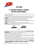
2.3 Foot Pedal and Power Connection
Connect the 3-pin plug for the foot pedal in the rear of the
press control assembly. Turn the locking ring clockwise until
tight. Connect the power cord plug to the socket in the back
of the control assembly. Use a grounded electrical outlet as
the power source. See Figure 2-2.
FOOT PEDAL
ASSEMBLY
PRESS CONTROL
ASSEMBLY
Figure 2-1
OILER ASSEMBLY
MOTOR
REEL SUPPORT
ASSEMBLY
TERMINAL GUIDE
POWER CORD
WORK BENCH
LIFT HOOK
WORK LIGHT

TM-3000 Universal Press
Order No 63801-7299 Release Date: 06-06-05 UNCONTROLLED COPY Page 8 of 29
Revision: A Revision Date: 06-06-05
POWER
CORD PLUG
Figure 2-2
FOOTSWITCH
CORD
PULL UP FROM
HOLE, ROTATE AND
SLIDE DOWN INTO
HOLE
REPOSITION
TERMINAL GUIDE
Figure 2-3
REMOVE M6 BHCS
AND REMOVE
TERMINAL GUIDE
LOOSEN
M10 SSS IN
FRONT OF
PRESS
2.4 Pneumatic Supply Hook-Up
A compressed air supply is required if air feed or other air
powered applicators will be used. The TM3000 press comes
equipped with an air supply system, which consists of filter,
regulator, lubricator and a valve to actuate the air feeds at the
proper time in the press cycle.
Due to the considerable types of air connection and quick
connect fittings available; Molex only supplies the TM3000 press
with a 1/4 NPT female threaded fitting. The customer may
attach whatever type of air connections that are commonly used
in their plant to this port.
The minimum flexible tube size used to connect the press should
be 8mm or 5/16” to assure adequate flow rate.
A filter-regulator-lubricator unit is supplied to properly condition
the incoming air. The filter will remove particulate and moisture
from the air that can damage or reduce the life of cylinders and
valves. This filter and bowl should be serviced on a regular
schedule. (See section 4.1) The filter has an automatic drain at
the bottom of the bowl that will automatically open and expel
fluid when the bowl is getting full. It is recommended that, a
6mm or 1/4” flexible tube, be attached to the drain hose barb
and run to a container if the air system contains excessive
moisture.
The regulator adjusts the pressure of the incoming air to what
the applicators require usually 60-80 PSI (refer to the applicator
manual for recommended pressures.) Adjustment is
accomplished by pulling up on the knob, rotating it until the
gauge indicates the desired pressure, then pushing it down to
lock the setting.
A lubricator is supplied for those applicator air feeds that need
lubrication. Molex air-feed applicators do not require
lubrication. The lubricator is shipped without lubricant in it. To
use, fill the lubricator (make sure the main air supply is
disconnected or that the slide valve provided is in the off position
before adding lubricant) through the fill plug on the top of the
unit, with a high quality SAE 10 W oil. The lubricator has a
graduated dial on top, turn the dial to the 1 or 2 setting.
Caution: Do not over lubricate. Only a very small amount of
lubricant is required to assure smooth operation. Excess lubricant
is exhausted to the atmosphere.
If lubrication is not required set the dial to 0 to turn off the
lubricator.
2.5 Terminal Feed Guide
Depending on side or rear-feed applications, the terminal
guide plate and bracket must be repositioned.
The TM-3000 press is set for side-feed applicators when
shipped from the factory. When rear-feed applicators are
used, the two M6 BHCS from the terminal guide-mounting
bracket are to be removed. See Figure 2-3. The guide
bracket is rotated 180 degrees and the assembly is then
mounted on the two standoffs in the rear of the press with the
two M6 SHCS. See Figure 2-3.

TM-3000 Universal Press
Order No 63801-7299 Release Date: 06-06-05 UNCONTROLLED COPY Page 9 of 29
Revision: A Revision Date: 06-06-05
SHUT HEIGHT GAUGE
PRESS QUICK CHANGE
MOUNTING PLATE
Figure 2-4
PRESS
MOTOR ON
PUSH BUTTON
COUNTER
TOGGLE SWITCH
FOR FULL OR
SPLIT CYCLE
Figure 2-5
MAIN
POWER
FUSE HOLDER
2.6 Function Test
When the TM-3000 is shipped from the factory, it is set to the
industry shut height of 135.80 mm (5.346”) with a calibrated
load gauge. The press shut height gauge is spring loaded to
give an accurate reading on the press shut height. See Figure
2-4. Molex recommends hand cycling the press each time an
applicator is installed. See Section 3-3.
CAUTION: Always manually cycle the press before
restoring power to the machine.
2.6.1 Verification of Press Shut Height
This press comes factory set at an Industry Standard shut height
of 135.80mm (5.346”). A label is attached to the front of
each press indicating the factory settings. This press has an
adjustable shut height, see Section 3.4.3 for crimp height
adjustment. Always return the press to the factory setting on
the label before installing applicators to avoid tooling damage.
Check the factory setting periodically with a calibrated shut
height gage.
Shut height gauges may be purchased from:
Artos Eng. 602-581-0070
Komax Corp. 847-537-6640
The gauges should come with instructions for use and
calibration.
2.7 Safety and Work Area Check
Check that the crimping position is ergonomic for the
operator’s size. A bench height of 762.00 to 813.00mm
(30.00 to 32.00”) will provide operator comfort, and
allows both feet to rest on the floor. The foot pedal
should be placed in a comfortable position. Check that
the press position is located approximately 150.00mm
(6.00“) from the edge of the bench. A chair or stool with
adjustable height and backrest should be provided for
maximum comfort and back support for the operator.
See Figure 2-5 for the control panel.
CAUTION: Molex recommends that the operator and
observers wear eye protection when the press is in operation
or being serviced.
The fuse is located on the control panel. To replace the
fuse (10AMP on 110 V models and 5AMP on 220V
models), turn the holder in the direction as shown. Turn
clockwise to secure holder in place when replaced. See
Figure 2-5.

TM-3000 Universal Press
Order No 63801-7299 Release Date: 06-06-05 UNCONTROLLED COPY Page 10 of 29
Revision: A Revision Date: 06-06-05
Section 3
Setup and Operation
3.1 Applicator Installation
3.2 Air Feed Applicator Installation
3.3 Manually Cycling the Press
3.4 Operation

TM-3000 Universal Press
Order No 63801-7299 Release Date: 06-06-05 UNCONTROLLED COPY Page 11 of 29
Revision: A Revision Date: 06-06-05
QUICK
CHANGE
PLATE
LOCATOR
CLAMPS
LOCKING
CLAMP
USE 4mm
HEX WRENCH
Figure 3-1
ENGAGE
PRESS YOKE
BASE PLATE
LUG BOLT
TO MAIN
AIR SUPPLY
SHUT-OFF
SLEEVE
Figure 3-2
FILTER-REG-LUBRICATOR
SLIDE LEFT TO
SHUT OFF
3.1 Applicator Installation
Power down the press by turning off the “ON” switch located
on the control panel.
Note: Once the press guard is open the guard interlock
switch will disconnect power to the motor.
Steps
1. Swing the press guard open.
2. Verify that the applicator is correctly tooled for the
terminal being used. (Reference specification sheets
supplied with the applicator).
3. Clean the press quick change mounting plate of scrap or
chips that may interfere with the applicator installation.
4. Using a 4mm hex wrench, turn the M5 SHCS clockwise
until the locking clamp is fully opened.
5. Locate the applicator lug bolt in the press yoke. See
Figure 3-1.
6. Align the applicator base plate slots with the locator
clamps on the press quick change plate.
7. To lock applicator, turn M5 SHCS counter clockwise until
tight.
8. Confirm that the applicator is secured properly.
3.2 Air Feed Applicator Installation
Power down the press by turning off the “ON” switch, located
on the control panel.
Note: Once the press guard is open the guard interlock switch
will disconnect power to the motor.
Warning: When using air feed applicators, always use the
slide valve supplied to shut-off and vent air pressure to the air
feed before servicing. The guard interlock switch DOES NOT
remove air pressure. If an air feed is jammed and air pressure
is not removed before servicing, the feed could move
unexpectedly and cause injury.
Steps
1. Swing the press guard open.
2. Verify that the applicator is correctly tooled for the
terminal being used. (Reference specification sheets
supplied with the applicator).
3. Clean the press quick change mounting plate of scrap or
chips that may interfere with the applicator installation.
4. Using a 4mm hex wrench, turn the M5 SHCS clockwise
until the locking clamp is fully opened.
5. Locate the applicator lug bolt in the press yoke. See
Figure 3-1.
6. Align the applicator base plate slots with the locator
clamps on the press quick change mounting plate.
7. To lock applicator, turn M5 SHCS counter clockwise until
tight.
8. Confirm that the applicator is secured properly.
9. Disconnect the air supply from the filter-regulator-
lubricator supplied with the press, by sliding the shutoff
valve sleeve to the left, as shown in Figure 3-2. Remove

TM-3000 Universal Press
Order No 63801-7299 Release Date: 06-06-05 UNCONTROLLED COPY Page 12 of 29
Revision: A Revision Date: 06-06-05
TOGGLE SWITCH
TO FULL CYCLE
PUSH
MOTOR ON
Figure 3-5
POWER
ON
Figure 3-4
FOOT SWITCH
CORD
MOTOR
TURN
CLOCKWISE
T-HANDLE
WRENCH
POWER CORD
the plugs from the fittings on the air valve. Do not
discard the plugs; when the air applicator is not being
used, the fittings should be plugged.
Note: When not using an air feed applicator always shutoff the
air supply to the filter-regulator-lubricator by sliding the
shutoff valve sleeve to the left, the opposite direction of the
airflow, as shown in Figure 3-2.
Note: Some applicators feed terminals in the retracted position,
for those air tubes must be reversed. In addition, some
applicators are air advance and spring return, on these
applicators one port will need to be plugged.
10. Insert the “A” port of the air valve with the tube that
retracts the feed mechanism of the applicator. See
Figure 3-3.
11. Insert the “B” port of the air valve with the tube that
advances the feed mechanism of the applicator. See
Figure 3-3.
12. Connect the main air supply to the filter reg-lubricator.
(Custumer supplied fitting)
13. Adjust the regulator to 75-80 PSI (366-390 KGf/cm
2
).
14. Check that the tubing for the applicator is properly
connected by dry cycling the press and observing the
feed motion.
3.3. Manually Cycling the Press
Power down the press by turning off the “ON” switch located
on the control panel.
Note: Once the press guard is open the guard interlock
switch will disconnect power to the motor.
Hand cycling the press is necessary to confirm correct
tool alignment and terminal feed adjustment. It also
gives the setup person the ability to step through the
press cycle manually.
PORT ”B”
Figure 3-3
AIR-FEED
APPLICATOR
PORT ”A”
ADVANCES
RETRACTS
FILTER-REG-
LUBRICATOR
TO MAIN
AIR SUPPLY

TM-3000 Universal Press
Order No 63801-7299 Release Date: 06-06-05 UNCONTROLLED COPY Page 13 of 29
Revision: A Revision Date: 06-06-05
Steps
1. Insert the 8mm square socket T-handle wrench through the
access hole in the center of the rear cover on the motor and
locate it in the shaft motor. See Figure 3-4.
2. Rotate the wrench clockwise. This turns the motor and
moves the ram down and up.
3. Always return the press back to top dead center insuring
that the ram is in the start up position.
4. Remove the T-handle wrench.
NOTE: When the T-handle is put into the motor shaft the
motor turns off automatically.
3.4. Operation
3.4.1 Full Cycle Operation
Caution: Make sure the press guard is in position and all
setup procedures are followed. Follow the safety and work
area instructions.
Steps:
1. Push the toggle switch on the control panel to “Full Cycle”.
See Figure 3-5.
2. Turn the “Power “ switch on, the power indicator light will light
up.
3. Press the “Motor On” push button, the motor indicator light
will light up. After a 5 second delay the press will be ready to
cycle.
4. Place the prestripped wire through the slot in the press guard
and push until it contacts the wire stop. See Figure 3-6.
5. Press the foot pedal down once. Use a sweeping motion to the
right with the crimped wire and remove.
6. Check the crimped wire and confirm that it meets the
applicator specifications and visual inspection.
7. Repeat steps 4 and 5 for the next crimp.
3.4.2 Split Cycle Operation
Desription:
The split cycle is used mostly for closed barrel terminals. This
makes it easier to locate the terminal before crimping the
wire. The punch/ram will close partially to assist in locating
the terminal for the termination. Then the wire can be placed
into the terminal and be terminated. To setup the machine for
split cycle push the toggle switch on the control panel to “Split
Cycle”. See Figure 3-5.
Steps:
1. Depress the foot switch once, the ram will lower partially,
positioning the terminal for termination.
2. Place the prestripped wire into the terminal.
3. Depress the foot switch a second time. The ram will complete
its downward stroke and return to the top position to complete
the cycle of terminating the crimp.
Caution: Make sure the press guard is in position and all
setup procedures are followed. Follow the safety and work
area instructions.
Split Cycle Ram Adjustment
When setting up an applicator for split cycle operation it may
be necessary to adjust the ram for a partially closed position
(1
st
position), so the terminal will be captivated in the punch
and not terminated. For adjustment, the prox sensor located
on the left side of the ram cover, needs to be adjusted. See
the following steps:
Steps:
1. Depress the foot switch once, with the terminals in the
applicator. See where the punch is located in the 1
st
position
of the cycle.
2. If the punch is too high and does not center the terminal so
that the prestripped wire can be inserted in the closed barrel
or the punch is too low partially crimping the terminal, the
prox sensor needs to be adjusted.
WIRE
STOP
PRE-STRIPPED
WIRE
Figure 3-6
GUARD

TM-3000 Universal Press
Order No 63801-7299 Release Date: 06-06-05 UNCONTROLLED COPY Page 14 of 29
Revision: A Revision Date: 06-06-05
ADJUSTABLE
DIAL
LOOSEN
M6 SHCS
Figure 3-8
LOOSEN
M6 SHCS
1.52mm
(.06”)
MAX. GAP
M4 JAMNUT
Figure 3-7
PROX SENSOR
M12 JAM NUT
PROX BRACKET
TOGGLE SWITCH
TO SPLIT CYCLE
3. Open the press guard.
4. Loosen the two M12 jam nuts on the split cycle prox, located
on both sides of the prox bracket. Then loosen the M4 jam
nut holding the M4 X 25 SHCS. Turn the screw clockwise to
raise the prox or counter-clockwise to lower the prox. See
Figure 3-7. Raise the prox if the punch is partially crimping
the terminal; or lower the prox if the ram is not closing far
enough and not centering the terminal punch.
5. Retighten the M4 SHCS and the (2)M12 jam nuts positioning
the prox for the 1
st
position of the split cycle. See Figure 3-7.
6. Close the press guard.
7. Repeat step 1 to check for the correct position of the ram. (Be
sure Ram is at Top-Dead-Center first.)
Note: The gap between the prox and the ram should be
1.52mm(.06”) Max. See Figure 3-7.
Caution: Always return the ram to the top dead center
position or start position of the cycle before recycling the
press. This is done by manually cycling the press. See
section 3.2.
3.4.3 Crimp Adjustment
See Section 2.6.1 for Industry standard shut height.
Crimp Adjustment Full and Split Cycle
If crimp adjustment is required and cannot be made by the cam
adjustment on the applicator, the fine adjustment dial on the press
ram can be adjusted by following the steps below.
Steps:
1. Open the press guard.
2. Loosen the four M6 SHCSs on the front of the press.
3. Rotate the adjustment dial to the right to raise crimp height or
to the left to decrease. Dial indicator lines represent
increments of .05mm (.002”). See Figure 3-8.
4. When adjustment is complete, retighten the four M6 SHCSs.
5. Close the guard.
6. Place a prestripped wire into the terminal and terminate under
power. Examine the quality of the crimp.
7. Repeat steps 1 thru 6 if the desired crimp is not achieved.
Use caution adjusting the ram downward. Over adjustment
in this direction may cause tooling damage or breakage.
Always return the adjustment to the factory setting before
installing another applicator, or recalibrating shut height.
See Section 2.6.1.

TM-3000 Universal Press
Order No 63801-7299 Release Date: 06-06-05 UNCONTROLLED COPY Page 15 of 29
Revision: A Revision Date: 06-06-05
Section 4
4.1 Maintenance
4.2 Oiler
4.3 Troubleshooting

TM-3000 Universal Press
Order No 63801-7299 Release Date: 06-06-05 UNCONTROLLED COPY Page 16 of 29
Revision: A Revision Date: 06-06-05
OIL CUP
GREASE FITTING Figure 4-8
LID
TUBE
WICK
(PKG OF (25
#638900727)
MOUNTING
BRACKET
JAR
(OIL RESERVOIR)
Figure 4-9 OILER ASSEMBLY
4.1 Maintenance
Power down the press by pressing the power button
to off “O” located on the control panel.
The TM-3000 press requires very little maintenance.
For efficient operation the TM-3000 press should be cleaned
daily with a soft bristle brush to remove any carrier strip
debris and terminal plating dust from the tooling area.
Maintenance Schedule
The following is offered as a general guideline for maintenance.
Tool life can be increased with good maintenance practices or
decrease with lack of maintenance.
Item
Frequency
Cycles
Frequency
Time
Materials
Air Filter 100,000 Weekly
Clean bowl and sintered
filter with denatured alcohol
Air Lubricator 100,000 Weekly
SAE 10W oil. Check and
refill if used
Ram 25,000 Daily
SAE 10W oil
Oil Cup (Top of ram)
Main Bearing 25,000 Daily
Grease fitting right side of
Press bearing lube
Cleaning 25,000 Daily
Use soft bristle brush on
Applicator mounting plate
4.2. Oiler
Description
The wick action oiler is included with the TM-3000 Press. The
oiler applies a thin coat of lubricant to the terminals, which
helps with feeding and better release from termination
punches. The oiler is primarily used for terminals with gold
plating. To avoid contamination when shipped and during
setup, the oiler is shipped from the factory with no lubricant oil.
The oiler should only be used on applicators that require
lubrication for smooth trouble-free operation.
Oiler Position
Adjust the position of the oiler unit using the mounting screw
that attaches the oiler to the quick change mounting plate.
Simply loosen the screw, slide the unit to the desired position,
and tighten the screw. The unit can be removed and placed
on the rear side of the quick change mounting plate for rear-
feed applications.
Oiler Wick
Adjust the height of the oiler wick by pulling up or pushing
down on the wick to the appropriate height. The wick can be
moved using pliers or simply grab it with your fingers.
Filling the Reservoir
While firmly holding the lid, screw the jar (oil reservoir)
counter clockwise until it is removed. Fill the jar with the
desired lubricant oil and replace the lid.

TM-3000 Universal Press
Order No 63801-7299 Release Date: 06-06-05 UNCONTROLLED COPY Page 17 of 29
Revision: A Revision Date: 06-06-05
Replacing the Wick
While firmly holding the lid, screw the jar oil reservoir)
counter clockwise until it is removed. Feed a new wick up into
the tube until it protrudes from the top end of the tube and
replace the lid.
Package of 25 Wicks: Molex Order No: 63890-0727
Lubricant Oil
Recommended oil: Transdraw B-19
Vendor: Sure Lubricants Inc.
356 South Lively Boulevard
Elk Grove Village, IL 60007-2010
Phone: 888-787-3582
Fax: 847-956-6655
E-mail: surelub@aol.com

TM-3000 Universal Press
Order No 63801-7299 Release Date: 06-06--05 UNCONTROLLED COPY Page 18 of 29
Revision: A Revision Date: 06-06-05
4.3 Troubleshooting
Symptom § Cause Solution
§ Power/Power cord failure Check supply
§ Loose connection Refer to control schematic
§ Guard interlock switch disengaged Re-Install guard
§ Fuse blown Replace
§ On/Off switch failure Replace
§ Motor failure Replace
§ T-wrench not removed from motor
Removed T-wrench from motor
§ Control PCB not working Replace
§ Solid state relay not working Replace
Motor will not run
§ Control board for motor Repair or replace
§ Guard interlock switch disengaged Re-Install guard
§ Faulty footswitch Check Connection. Repair or replace
§ Control PCB not working Replace
Press will not cycle
§ Fuse blown Replace
Press partially cycles § Toggle switch set to split cycle Reset the toggle switch to full cycle

TM-3000 Universal Press
Order No 63801-7299 Release Date: 06-06-05 UNCONTROLLED COPY Page 19 of 29
Revision: A Revision Date: 06-06-05
Section 5
5.1 Parts List
5.2 Assembly Drawings
5.3 Electrical and Pnuematic Schematics
1/30