Page is loading ...

Rifton Stander
S410 Product Manual
Stander

2© 2023 Rifton Equipment
Contents
Important information; Check your order 3
Safety messages 4
Recommended use; User and item dimensions 5
Critical supports 6
Basic item frame 7
Wheels; Height adjustment; Caregiver handle 7
Tilt adjustment; Body support; Trunk laterals; Strap attachment 8
Leg supports; Abduction; Sandals 9
Basic item PRONE 10
Trunk strap; Pelvic harness 10
Basic item SUPINE 11
Upper trunk support; Arm supports 11
Headrest; Trunk strap 12
Hip strap; Knee straps 13
Basic item MULTI-POSITION 14
Conversion kits 14
Optional components 15
Tray; Medial/lateral thigh supports 15
Head laterals; Butterfly harness; Prone knee cuffs 16
Operation 17–19
Positioning basics; Positioning smallest users 17
Transfers 18 – 19
Prone/Supine conversion 20–21
Materials; Maintenance 22
Cleaning; Warranty; User modifications 23

3
IMPORTANT
Please save this product manual for future reference. Additional copies are
available at www.rifton.com.
Key for users
Use this key to determine which sections of this product manual apply to you.
Technical Users For professionals who order and set up Rifton products.
Home Users For care-givers who use Rifton products on a regular basis.
Maintenance Personnel For anyone who is responsible for service or
re-ordering of Rifton products and parts.
Check your order
Your Rifton Stander comes assembled in one carton, though you may need to attach some
of the components. Check that all required components and the optional components you
selected are present. (You may not have ordered all of the available components.)
If your shipment is incomplete or in any way damaged on arrival, please call
Customer Service, 800.571.8198.

4
WARNING
• Thoroughly read and understand the information in this product manual before attempting
to use this product. If the procedures and instructions in this product manual are not
followed, serious injury or death could occur.
• A qualified professional must assess the appropriateness and safety of all equipment for each
user.
• A qualified medical professional must perform the initial set-up of the Stander, and must
ensure that other caregivers are trained in correct operation.
• This product is intended for use by clients of unreliable judgment. Adult supervision is
required at all times.
• To prevent falls and injuries:
○Do not use this product on rough and uneven terrain, around swimming pools, or near
stairways.
○Ensure the appropriate use of straps and supports at all times. Straps and supports
are provided for the safety of the user and must be carefully adjusted for comfort and
security.
○Ensure that you use all the correct straps and supports for the specific Stander
configuration (prone or supine). Refer to the labeling and this manual.
○Tighten all adjustment knobs before use and immediately after making any adjustments.
○Lock brakes at all times except when transporting the Stander, and lock brakes for all
transfers in and out of the product.
• To prevent tipping and resulting injury:
○Use the Rifton Stander indoors only.
○When moving the Stander, hold the push handle firmly, move at a slow and controlled
speed, and take extra care on doorsills, ramps, corners, and any uneven surfaces.
• Do not use this product for clients outside the height and weight limits specified in this
manual.
• To prevent structural failure, which may result in serious injury or death:
○Inspect this product and components regularly for loose or missing screws, metal fatigue,
cracks, broken welds, missing attachments, general instability or other signs of excessive
wear.
○Immediately remove this product from use when any condition develops that might make
operation unsafe.
○Do not use Rifton components or products for any purpose other than their intended use.

5
Recommended use
The Rifton Stander is a Class 1 medical device. It is intended to position people with
disabilities in standing, providing the health and therapeutic benefits of supported
standing. The Rifton Stander allows for growth and can be configured for prone or supine
standing. The multi-position configuration allows both. A variety of padded supports,
straps and adjustments allow comfortable and precise positioning for users with different
physical needs. Configuration and initial setup should be done by a qualified medical
professional.
User and item dimensions
User dimensions – inches (cm) Size 1
Height 28 – 42 (71–107)
Key user dimension: height
The user’s overall height is a general guide to help you select the
appropriate size. Choose the model that allows for growth.
Important: User’s weight must not exceed the maximum working load.
Item dimensions – inches (cm) Size 1
Base length 32½ (83)
Base width 21½ (55)
Horizontal body support height
above floor 22–28 (56–71)
Sandal to knee height 6¾ –11 (17 –28)
Knee to hip height 6¼ –10½ (16 – 27)
Sandal to top of headrest 31½ – 43 (80 –109)
Distance between trunk laterals 5½ – 10 (14 – 25)
Distance between thigh medial and
lateral support 2½ – 4 (6 –10)
Basic item weight (Prone) 47 lbs (21 kg)
Basic item weight (Supine) 52 lbs (23.5 kg)
Max. working load in lbs (kg) 75 (34 kg)

6
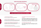
To avoid falls or
strangulation,
always ensure the correct straps and
supports are used in each configuration.
The infographic to the right shows the
minimum straps and supports required
for safe positioning in prone and supine
standing.
These minimum supports are denoted
throughout this guide by * for supine
and * for prone.
Figure 6a: Straps have color coded tags.
Use components with GREEN tags for
supine positioning, and components with
BLUE tags for prone positioning.
WARNING
Figure 6a
Critical supports

7
Basic item frame
Figure 7a
Figure 7b
Product can tip over
if used incorrectly.
Always engage brakes during transfers
and standing.
Wheels / Brakes
The wheeled base has two large wheels
on the side and casters at the front and
rear for excellent maneuverability. When
the stander is loaded, the rear caster is
intentionally raised slightly off the floor,
which helps when negotiating doorsills or
uneven floors. Foot operated brakes are
located on both of the large wheels.
Figure 7a: Press down on the white pedal
to lock brake, kick forward on the top tab
to release.
Height Adjustment
The column allows 6 inches of height
adjustment, with gas spring assist.
Figure 7b: Grasp the handle on top of the
column and squeeze the white trigger to
unlock and adjust the height. You may
need to take some of the body support
weight with your other hand.
Caregiver handle
Use the caregiver handle for steering
and pushing the Stander, as well as for
adjusting the body support angle.
Figure 7c: Adjust the handle position using
the knob at the attachment point. Always
ensure the handle adjustment knob is tight
before changing the body support angle or
moving the Stander.
WARNING
Figure 7c
Lock
Release
AA

8
Figure 8a
Figure 8b
Figure 8c
AA
1
2
BBCC
Figure 8d
Tilt adjustment
To prevent falls or
other injury, ensure all
straps are secure and knobs tight before
tilting client to a standing position.
The body support can be adjusted from
horizontal to completely vertical (90°).
Figure 8a: Grasp the caregiver handle
firmly and squeeze the double trigger to
adjust the body support angle. Release the
triggers to lock the adjustment.
Body support and trunk
laterals
The body support is the central padded
section where the upper trunk support,
trunk laterals and several straps attach.
The trunk laterals may be used at the trunk,
at the pelvis, or in both positions if
a second pair of laterals was selected.
Figures 8b and 8c: Use the white triggers
(A) on the side of the body support for
width adjustment or removal. Use the knob
(B) to adjust the height of each lateral pad,
and use the white trigger (C) to swing
lateral away for ease of transfer.
Strap attachment
All straps on the body support attach with
similar clips.
Figure 8d: Insert the tip of the clip into
corresponding socket behind the body
support and pull forward until it clicks. Pull
the clip back away from the pad to remove
the strap.
CC
WARNING

9
Figure 9a
Figure 9b
Leg supports
Figure 9a: Adjust the padded leg supports
so that the pad is centered at the user’s
knee. The inside knob (A) adjusts thigh
length, and the outside knob (B) adjusts
lower leg length.
Abduction
The Rifton Stander provides independent
abduction up to 30° for each leg.
Figure 9b: Loosen knob (C) behind the hip
joint to adjust hip abduction.
Sandals
The sandals have adjustable heel cups and
straps with buckles to position and secure
the feet.
Figure 9c: Loosen the knob underneath (D)
to rotate the sandal or adjust it forward
and back. Use the knob toward the outside
of the sandal (E) to adjust the ankle plantar
flexion/dorsiflexion through a total of 30°.
Rotate the sandal 180° to switch between
prone and supine configuration.
Figure 9c
AA
BB
CC
DD
EE

10
Figure 10a
See pages 7 – 9 for base frame, body
support, leg, sandal, and height
adjustments.
Trunk strap*
To prevent falls or
other injury, all users
should be secured with a trunk strap
(standard or rotation control) in prone
standing.
A trunk strap (standard or rotation control)
stabilizes the trunk and is required for
prone standing.
Figure 10a: The padded trunk strap
attaches under the arms and securely
positions the upper body.
Figure 10b: To attach the trunk rotation
control strap, detach the top end of the
trunk pad and slide the webbing loop
down behind the pad. Re-attach the trunk
pad, then clip the ends of webbing strap to
the body support. Close the strap snugly
around the user, then close the buckle and
tighten either side to control trunk rotation.
Pelvic harness*
To prevent
strangulation or
other injury, in prone standing the prone
pelvic harness MUST be used with all five
attachment points secured.
In prone standing the pelvic harness
provides critical support behind the user’s
hips to maintain the standing position. This
is a shaped, padded harness, with a 5-point
attachment system for safety.
Figure 10c: Tighten lower straps first to
secure the harness low under the user’s
hips and provide ideal support. Then
secure the remaining straps and adjust
until snug. Use the three buckles on the
right side and center when transferring the
user in and out.
WARNING
Figure 10c
WARNING
Figure 10b
Basic item PRONE

11
Basic item SUPINE
See pages 7 – 9 for base frame, body
support, leg, sandal, and height
adjustments.
Upper trunk support
The upper trunk support includes head and
arm support and attaches to the top of the
body support.
Attaching
Figure 11a: To attach the upper trunk
support, tilt it back 45° from the plane of
the body support and insert stampings
into slots.
Adjusting
Figure 11b: Squeeze the white triggers to
adjust the upper trunk support height. It
should be adjusted near the top of the user’s
shoulders, although it is fine for smaller
users to end up lower on the pad.
Arm supports
Figure 11c: The padded arm supports are
mounted permanently on either side of the
upper trunk support. They provide support
behind the arms in supine positions. A
knob (A) behind the attachment point
allows each arm support to swing up out
of the way behind the headrest during
transfers.
Figure 11a
Figure 11b
Figure 11c
AA

12
Headrest
Figure 12a: The headrest is attached to
the upper trunk support and provides
posterior support for the user’s head.
Attach optional head laterals for additional
support (see p. 16).
Trunk strap*
To prevent falls or
other injury, all users
should be secured with a trunk strap
(standard or rotation control) or butterfly
harness in supine standing.
A trunk strap (standard or rotation control)
securely positions and stabilizes the trunk.
For additional upper trunk positioning
and stabilization, a butterfly harness may
be used in supine standing. See p. 16
for full instructions and important safety
information.
A trunk strap (standard or rotation control)
or a butterfly harness is required for supine
standing.
Figure 12b: The padded trunk strap
attaches under the arms and securely
positions the upper body.
Figure 12c: To attach the trunk rotation
control strap, detach the bottom end of
the trunk pad and slide the webbing loop
up behind the pad. Re-attach the trunk
pad, then clip the ends of webbing strap to
the body support. Close the strap snugly
around the user, then close the buckle and
tighten either side to control trunk rotation.
Figure 12a
Figure 12b
WARNING
Figure 12c

13
WARNING
Figure 13a
Figure 13c
AA
Supine hip strap*
SUPINE ONLY
A hip strap (standard or rotation control) is
required for supine standing.
Figure 13a: The padded supine hip strap
provides support around the hips and
positions the user securely on the body
support.
Figure 13b: To attach the hip rotation
control strap, detach the bottom end of
the trunk pad and slide the webbing loop
up behind the pad. Re-attach the trunk
pad, then clip the ends of webbing strap to
the body support. Close the strap snugly
around the user, then close the buckle and
tighten either side to control trunk rotation.
Knee straps*
To prevent
strangulation or other
injury, in supine standing the user’s knees
MUST be secured with knee straps.
Figure 13c: The individual padded knee
straps clip onto the leg supports at either side
of each knee with a keyhole type attachment
onto the posts provided (A). These split knee
straps have an opening at the patella for user
comfort, and may be tightened securely by
pulling the strap ends. The posts on the sides
of the leg supports should align with the
user’s knees for correct strap placement.
Loosen the strap by lifting the plastic tab
on the attachment clip and unclip one
end from the post to release the strap
completely.
Figure 13b

14
Basic item MULTI-POSITION
The multi-position option has all the
features and components of both Prone
and Supine Standers described above
and may include any of the optional
components selected as well. The multi-
position option enables both prone and
supine configurations.
To upgrade your device from a prone or
supine stander to a multi-position stander,
select the appropriate upgrade kit below.
PRONE to MULTI-POSITION
Figure 14a: Choosing this option will
upgrade a Prone Stander to the multi-
position Stander by adding the functionality
of supine standing. This package includes
the upper trunk support with attached
headrest and arm supports, a supine hip
strap, and a pair of supine knee straps.
SUPINE to MULTI-POSITION
Figure 14b: Choosing this option will
upgrade a Supine Stander to the multi-
position Stander by adding the functionality
of prone standing. This adds the prone
pelvic harness to the product.
Figure 14a
Figure 14b
OR

15
Optional Components
Figure 15b
Tray
Attaching
Figure 15a: The tray has a single mounting
point at the side of the Stander, and may
be used in either Prone or Supine standing.
To attach the tray, insert the bolt on the
tray arm into the socket at the side of the
Stander. Push the knob (A) up and turn to
tighten.
Adjusting
Figure 15b: Adjust the tray position easily by
loosening all 3 knobs that face downward
and moving tray to the desired position
before tightening the knobs again. The knob
under the center of the tray (B) also allows
tray angle adjustment. To adjust the tray
height use the knob (C) that faces forward.
Medial/lateral thigh
supports
One or two pairs of thigh support pads
may be used. When used at the medial
thigh they provide an abductor function.
Mount the medial/lateral thigh supports
on the inside for medial support, or on the
outside for lateral support.
Figure 15c: Adjust the width using the
white trigger (D). The mounting bracket
is off-center, so the pad has two possible
height positions. Swap pads to change
height position.
Figure 15a
AA
BB
CC
Figure 15c
DD

16
Head laterals
Figure 16a: Add a pair of head laterals for
additional head support and control. To
attach, insert at the top of the slot and
slide down to desired position. Loosen the
knob (A) to adjust independently in height
and width.
Butterfly harness
To prevent
strangulation, always
attach center safety strap and make sure
all straps are snug before every use.
Figure 16b: In supine standing a butterfly
harness may be used in place of a trunk
strap. The butterfly harness provides more
upper trunk positioning and stabilization.
For safety, always use all five attachment
points.
Prone knee cuffs
PRONE ONLY
Figure 16c: Prone knee cuffs are available
for prone standing only. They wrap around
the user’s knee and give some medial/
lateral stabilization of the knee on the
padded leg support. They are also useful
for preventing knee hyperextension when
necessary.
In addition, some degree of rotational
control can be achieved by tightening the
strap on one side of the cuff more than
the other.
WARNING
AA
Figure 16a
Figure 16b
Figure 16c

17
Positioning basics
Figure 17a: To position the user at the
correct height in the stander, align their
hips with the “HIP” tags (A) on either side
of the body support. Remember that the
user may tend to sink down slightly in the
stander when it is tilted toward vertical, so
it may help to position them slightly higher
to begin with.
When adjusting leg length or upper trunk
support height to fit the user, ensure that
the user’s hips remain in line with the
“HIP” tags.
Figure 17b: For correct alignment of the
leg pads and knee straps, the user’s knee
should line up with the strap attachment
posts (B) on either side.
To position the pelvic harness correctly in
prone, tighten the lower side straps first to
get the support low and tight under the hips
and comfortably support the user’s weight.
Check for any pressure areas and adjust the
supports to relieve them. You may need to
move the sandals forward or back to get
the leg comfortably supported against the
leg pad.
Positioning smallest users
in size 1 Stander:
(users 28"– 32" tall)
For the smallest users, use one set of trunk
laterals in the lower position and attach
the trunk strap in the lower position on the
body support.
AA
Figure 17a
Figure 17b
BB
Operation
The Rifton Stander is intended to allow users who may be unable to stand independently
to be positioned safely in prone or supine standing, up to fully vertical as needed. Review
the following positioning and transfer information for proper operation of this Stander, and
also refer to the safety information on page 4 of this product manual.

18
Transfers
Follow these steps for easy transfer into the
Stander:
Prone transfer 1
(sit-to-stand transfer)
Figure 18a:
1. Measure from the center of the user’s
knee to the bottom of their foot and set
lower leg length on the Stander to match.
2. Measure from the center of the user’s
hip to the center of their knee and set
thigh length on the Stander to match.
3. Position the Stander close to the client
with the body support nearly vertical.
Lock the brakes.
4. Place the user’s feet on the sandals, legs
against the pads.
5. Help the client to stand up and secure
the pelvic harness.
6. Apply the other straps and supports,
and secure the sandal straps.
7. Check that minimum required supports
for prone standing are secure:
• Trunk strap (standard or rotation
control)
• Pelvic harness – 5 straps
• Sandals
8. Adjust to desired angle
for standing.
Prone transfer 2 (lifting transfer)
Figure 19a:
1. Measure from the center of the user’s
knee to the bottom of their foot and set
lower leg length on the Stander to match.
2. Measure from the center of the user’s
hip to the center of their knee and set
thigh length on the Stander to match.
3. Adjust the stander to horizontal or near
horizontal and lock the brakes.
Figure 18a

19
4. Lift the user into the stander and secure the
pelvic harness.
5. Apply the other straps and supports and
secure the sandal straps.
6. Check that minimum required supports for
prone standing are secure:
• Trunk strap (standard or rotation control)
• Pelvic harness – 5 straps
• Sandals
7. Adjust to desired angle for standing.
Supine transfer Figure 19b:
1. Measure from the center of the user’s knee
to the bottom of their foot and set lower leg
length on the Stander to match.
2. Measure from the center of the user’s hip to
the center of their knee and set thigh length
on the Stander to match.
3. Position the Stander horizontal at the
desired height for transfer. Lock the brakes.
4. Open the straps and swing the laterals out
of the way.
5. Lift the user onto the Stander and align hips
with the hip markers on the stander. Secure
the hip strap first.
6. Adjust thigh and lower leg length if
necessary.
7. Ensure the posts on the sides of leg supports
align with user’s knees for correct strap
placement. Secure the knee straps.
8. Apply the other straps and supports and
secure the sandal straps.
9. Check that minimum required supports for
prone standing are secure:
• Trunk strap (standard or rotation control)
or butterfly harness
• Supine hip strap (standard or rotation
control)
• Knee straps
• Sandals
10. Adjust to the desired angle for standing.
Figure 19b
Figure 19a

20
PRONE / SUPINE conversion
Multi-Position Stander only
It is very important to configure the product
correctly and to ensure that the correct
straps and supports are used in each
position. Straps have color coded tags. Use
components with GREEN tags for supine
positioning, and components with BLUE
tags for prone positioning.
Switching to PRONE
1. Remove upper trunk support
Squeeze the triggers on the back of the
trunk support. Pull the upper trunk support
up and tilt it back to remove it.
2. Switch tray direction
If the tray is used, loosen attachment knob
(A), remove the tray and attach it facing
the other direction. For use in prone, adjust
the tray up and the caregiver handle down
and out of the way.
3. Switch to pelvic harness
Remove the supine hip strap. Install the
pelvic harness by attaching all 5 straps.
4. Remove knee straps
Optional prone knee cuffs may be added.
5. Rotate sandals 180°
Loosen the knob under the sandal (B),
rotate them so that heel cups are towards
the front of the stander, and tighten the
knob.
4
3
2
1
55
AA
BB
/