Page is loading ...

Installation instruc-
tions
DHP-A
DHP-A Opti
DHP-AL
DHP-AL Opti
DHP-C
DHP-H
DHP-H Opti Pro
DHP-L
DHP-L Opti
VMBMA702

If these instructions are not followed during installation and serv-
ice, Danfoss A/Sliability according to the applicable warranty is not
binding. Danfoss A/S retains the right to make changes to com-
ponents and specifications without prior notice.
© 2010 Copyright Danfoss A/S.
The Swedish language is used for the original instructions. Other
languages are a translation of original instructions.
(Directive 2006/42/EG)

Contents
1 About the instructions..................................................................... 3
1.1 Introduction..................................................................................... 3
1.2 Symbols............................................................................................. 3
1.3 Terminology..................................................................................... 3
2 Important information/Safety regulations............................... 4
2.1 Refrigerant........................................................................................ 5
2.2 Electrical connection..................................................................... 6
2.3 Commissioning............................................................................... 7
3 Check and safety functions............................................................ 8
4 Heat pump information................................................................ 11
4.1 DHP-H............................................................................................... 11
4.2 DHP-H Opti Pro............................................................................. 13
4.3 DHP-C............................................................................................... 15
4.4 DHP-L, DHP-L Opti....................................................................... 16
4.5 DHP-A, DHP-A Opti..................................................................... 18
4.6 DHP-AL, DHP-AL Opti................................................................. 21
4.7 Package contents......................................................................... 24
4.8 Transporting the heat pump................................................... 26
4.9 Space requirement...................................................................... 26
4.10 Recommended location......................................................... 27
4.11 Space requirement, outdoor unit, DHP-A, DHP-AL....... 28
4.12 Recommended location of outdoor unit, DHP-A, DHP-AL. 28
5 Drilling holes for brine pipes....................................................... 29
6 Separating the heat pump........................................................... 30
7 Unpacking and installation.......................................................... 33
7.1 Setting up....................................................................................... 33
7.2 Removing the front cover......................................................... 34
7.3 Unpacking and installing the outdoor unit........................ 34
8 Piping installation........................................................................... 39
8.1 Connection heat transfer fluid................................................ 39
8.2 System solution 1........................................................................ 41
8.3 System solution 2........................................................................ 44
8.4 System solution 3........................................................................ 46
8.5 Safety valves.................................................................................. 49
8.6 Noise information........................................................................ 50
8.7 Connecting cold and hot water lines................................... 51
8.8 Connecting the heating system supply and return lines. 51
8.9 Filling the water heater and heating system..................... 52
8.10 Bleeding the heating system................................................ 52
9 Electrical Installation...................................................................... 53
9.1 Cable connection......................................................................... 53
9.2 Electrical components............................................................... 54
9.3 Connecting external supply voltage.................................... 54
9.4 Position and connect outdoor sensors................................ 55
9.5 Changing the language in the control computer............ 55
9.6 Selection of system solution and connection of external aux. heater. 55
9.7 Changing the number of auxiliary heating power stages. 58
9.8 Connect outdoor unit, DHP-A, DHP-AL............................... 58
9.9 Connect defrost sensor, DHP-A, DHP-AL............................ 58
10 Brine installation........................................................................... 59
10.1 Heat sources................................................................................ 59
10.2 Information collector pipe..................................................... 62
10.3 Connection to outdoor unit.................................................. 63
10.4 Connection of several brine coils........................................ 63
10.5 Connection diagram................................................................ 65
10.6 Installing brine pipes................................................................ 67
10.7 Filling the brine system........................................................... 68
10.8 Bleeding the brine circuit....................................................... 70
10.9 Vent outdoor unit...................................................................... 70
11 Installing accessories/additional functions......................... 72
11.1 Room sensor............................................................................... 72
11.2 EVU function............................................................................... 73
11.3 Tariff control................................................................................ 73
11.4 Flow switch/level switch......................................................... 73
11.5 Higher hot water temperature............................................. 73
12 Menu information......................................................................... 75
13 INFORMATION menu................................................................... 77
13.1 Sub-menu OPERAT................................................................... 78
13.2 Sub-menu HEAT CURVE.......................................................... 79
13.3 Sub-menu HEAT CURVE 2...................................................... 79
13.4 Sub-menu TEMPERATURE...................................................... 80
13.5 Sub-menu OPERAT.TIME........................................................ 80
13.6 Sub-menu DEFROST................................................................. 80
13.7 Sub-menu LANGUAGE............................................................ 81
14 SERVICE menu................................................................................ 82
14.1 Sub-menu HOT WATER........................................................... 85
14.2 Sub-menu HEAT PUMP........................................................... 85
14.3 Sub-menu AUX. HEATER......................................................... 86
14.4 Sub-menu MANUAL TEST....................................................... 87
14.5 Sub-menu INSTALLATION...................................................... 89
14.6 Sub-menu DEFROST................................................................. 90
14.7 Sub menu OPTIMUM................................................................ 91
14.8 Sub-menu HGW......................................................................... 92
15 Important parameters................................................................. 93
15.1 Heat production - calculating............................................... 93
15.2 CURVE............................................................................................ 93
15.3 ROOM............................................................................................ 94
15.4 HEAT STOP................................................................................... 95
15.5 MIN and MAX.............................................................................. 95
15.6 TEMPERATURES.......................................................................... 95
15.7 INTEGRAL...................................................................................... 96
15.8 HYSTERESIS.................................................................................. 97
15.9 DEFR CURVE................................................................................ 97
16 Start up........................................................................................... 100
16.1 Installation checklist.............................................................. 100
16.2 Manual test................................................................................ 101
17 Commissioning........................................................................... 104
17.1 Starting circulation pumps manually.............................. 104
17.2 Adaptation to the heating system.................................... 104
17.3 Installing the front cover...................................................... 105
17.4 After start up............................................................................. 105
18 Customer information.............................................................. 106
19 Technical data, DHP-H.............................................................. 107
20 Technical data; DHP-H Opti Pro............................................ 109
21 Technical data, DHP-L............................................................... 111
22 Technical data, DHP-L Opti..................................................... 113
23 Technical data, DHP-C.............................................................. 115
24 Technical data, DHP-A.............................................................. 117
25 Technical data, DHP-A Opti.................................................... 119
VMBMA702 – 1


1 About the instructions
1.1 Introduction
The installation instructions start by describing heat pump data. The installation instructions later give instructions
in a logical order covering unpacking, installation procedure, and checking the installation.
References to chapters and sections within the instructions are in italics, e.g.: About the instructions.
References to menu options in the heat pump’s control system are in upper case, e.g.: INFORMATION ->OPERAT. ->
AUTO.
All figures in the instructions are numbered to help installers and service technicians refer to them easily.
1.2 Symbols
The instructions contain different warning symbols, which, together with text, indicate to the user that there are risks
involved with actions to be taken.
The symbols are displayed to the left of the text and three different symbols are used to indicate the degree of danger:
DANGER! Hazardous electrical voltage!Indicates an immediate danger that leads to fatal or serious injury if
necessary measures are not taken.
Warning! Risk of personal injury!Indicates a possible danger that can lead to fatal or serious injury if necessary
measures are not taken.
Caution! Risk of installation damage. Indicates a possible hazard that can lead to item damage if necessary
measures are not taken.
A fourth symbol is used to give practical information or tips on how to perform a procedure.
Note! Information regarding making the handling of the installation easier or a possible operational technical
disadvantage.
1.3 Terminology
The instructions contain terms throughout that designate components and functions. The table lists the most com-
mon terms that are used in the instructions.
Table 1. Terminology
Term Meaning
Heating system The circuit that generates heat to the property or to the water heater.
Supply line The heating system’s supply line with flow direction from the heat pump to radiators/
under floor heating or water heater.
Return line The heating system’s return line with flow direction from radiators/under floor heating or
water heater to the heat pump.
Circulation pump Circulation pump for heating system.
Refrigerant circuit The energy carrying circuit between the outdoor air and heating system.
Refrigerant The gas/liquid that circulates in the refrigerant circuit.
Installation instructions VMBMA702 – 3

2 Important information/Safety regulations
Warning! Risk of personal injury! Children are not permitted to play with the apparatus.
Warning! As the water temperature in DHP-H Opti Pro becomes extremely hot, a mixer valve must be installed
between the cold water and hot water pipes to ensure a lower domestic hot water temperature.
Warning! Danfoss SP (1-phase) heat pumps have a factory installed safety valve for temperature and pressure,
(10 bar 90-95° C), in accordance with the requirements in Great Britain. This valve is located in the water tank
and may not be used for any purpose other than connecting the outlet pipe.
Also note that for heat pump DHP-H Opti Pro SP it is imperative that the hot water temperature is changed
from default setting 95° C to 85° C.
Caution! The heat pump must be installed by authorised installation engineers and the installation must
follow the applicable local rules and regulations as well as these installation instructions.
Caution! This apparatus is not intended for persons (including children) with reduced physical, sensory or
psychological capacity, or who do not have knowledge or experience, unless supervised or they have
received instructions on how the apparatus functions from a safety qualified person.
Caution! The heat pump must be located in a frost-free environment!
Caution! The heat pump must be placed in an area with a floor drain.
Caution! The heat pump must be located on a stable base. The floor must be able to support the gross weight
of the heat pump with filled hot water tank (see Technical data).
Caution! To prevent leaks, ensure that there are no stresses in the connecting pipes!
Caution! It is important that the heating system is bled after installation.
Caution! Bleed valves must be installed where necessary.
4 – Installation instructions VMBMA702

Caution! The hot water tank must be equipped with an approved safety valve.
Caution! Heating systems with closed expansion tanks must also be supplied with approved pressure gauges
and safety valves.
Caution! Cold and hot water pipes and overflow pipes from safety valves must be made of heat resistant and
corrosion-resistant material, e.g. copper. The safety valve overflow pipes must have an open connection to
the drain and visibly flow into this in a frost-free environment.
Caution! The connecting pipe between the expansion tank and the safety valve must slope continuously
upwards. A continuous upwards slope means that the pipe must not slope downwards from the horizontal
at any point.
Note! If there is any risk of groundwater infiltration at wall lead-ins for brine pipes, watertight grommets
must be used.
Note! In addition to applicable local rules and regulations the installation should be carried out in a manner
that prevents vibrations from the heat pump being transmitted into the house causing noise.
2.1 Refrigerant
Caution! Work on the refrigerant circuit must only be carried out by a certified engineer!
Although the heat pump cooling system (refrigerant circuit) is filled with a chlorine-free and environmentally-
approved refrigerant that will not affect the ozone layer, work on this system may only be carried out by authorized
persons.
2.1.1 Fire risk
The refrigerant is not combustible or explosive in normal conditions.
2.1.2 Toxicity
In normal use and normal conditions the refrigerant has low toxicity. However, although the toxicity of the refrigerant
is low, it can cause injury (or be highly dangerous) in abnormal circumstances or where deliberately abused.
Warning! Risk of personal injury! Spaces in which heavy vapour can collect below the level of the air must
be well ventilated.
Refrigerant vapour is heavier than air and, in enclosed spaces below the level of a door for example, and in the event
of leakage, concentrations can arise with a resultant risk of suffocation due to a lack of oxygen.
Installation instructions VMBMA702 – 5

Warning! Risk of personal injury! Refrigerant exposed to a naked flame creates a poisonous irritating gas.
This gas can be detected by its odour even at concentrations below its permitted levels. Evacuate the area
until it has been sufficiently ventilated.
2.1.3 Work on the refrigerant circuit
Caution! When repairing the refrigerant circuit, the refrigerant must not be released from the heat pump, it
must treated in the appropriate way.
Draining and refilling must only be carried out using new refrigerant (for the amount and type of refrigerant see
manufacturer’s plate) through the service valves.
Caution! All warranties from Thermia Värme ABDanfoss A/S are void if, when filling with refrigerant other
than Thermia Värme ABDanfoss A/S specified refrigerant, if there has not been written notification that the
new refrigerant is an approved replacement refrigerant together with other remedies.
2.1.4 Scrapping
Caution! When the heat pump is to be scrapped the refrigerant must be extracted for disposal. Local rules
and regulations related to the disposal of refrigerant must be followed.
2.2 Electrical connection
Caution! Electrical installation may only be carried out by an authorized electrician and must follow
applicable local and national regulations.
Caution! The electrical installation must be carried out using permanently routed cables. It must be possible
to isolate the power supply using an all-pole circuit breaker with a minimum contact gap of 3 mm. (The
maximum load for externally connected units is 2A).
DANGER! Hazardous electrical voltage! The terminal blocks are live and can be highly dangerous due to the
risk of electric shock. All power supplies must be isolated before electrical installation is started. The heat
pump is connected internally at the factory, for this reason electrical installation consists mainly of the
connection of the power supply.
Note! The room sensor is connected to a safety extra-low voltage.
Follow the separate installation instructions for the room sensor!
6 – Installation instructions VMBMA702

2.3 Commissioning
Caution! The installation may only be commissioned if the heating system and brine system have been filled
and bled. Otherwise the circulation pumps can be damaged.
Caution! If the installation is only to be driven by an auxiliary heater during the installation, ensure that the
heating system is filled and the brine pump and compressor cannot be started. This is carried out by setting
the operating mode to AUX. HEATER.
Installation instructions VMBMA702 – 7

3 Check and safety functions
The heat pump has a number of check and safety functions to protect the installation against damage during abnor-
mal operating conditions.
The diagram below shows the heat pump's three circuits with respective safety functions.
1
2
6
5
4
7
9
3
8
Figure 1. Check and safety functions
Symbol explanation
1 Heat transfer fluid circuit
2 Safety valve, heat transfer fluid circuit, externally
mounted
3 Refrigerant circuit
4 Operating pressure switch, normal
5 Operating pressure switch, alternative
6 High pressure switch
7 Low pressure switch
8 Brine circuit
9 Safety valve, brine fluid circuit, externally mounted
Heat transfer fluid circuit (1)
If the pressure in this circuit exceeds the opening pressure for the safety valve (2), the valve opens, releases the
overpressure and closes again. The safety valve overflow pipe must have an open connection to the drain and visibly
flow into this in a frost-free environment.
Refrigerant circuit (3)
The refrigerant circuit's high pressure side is equipped with a high pressure switch (6) and two operating pressure
switches (4, 5), only one of which is connected. The connected operating pressure switch stops the compressor when
the working pressure is reached, which is when sufficient heat energy has been produced.
If the operating pressure switch does not work and the pressure continues to increase in the circuit, the high pressure
switch activates when its break pressure is reached, whereupon the compressor stops and the heat pump's normal
operation is blocked.
If the high pressure switch is activated an alarm indicator flashes on the heat pump's control panel and a warning
text appears in the display of the control panel. The blocked heat pump is reset by setting the operating mode to
OFF and then back to the previously selected mode (AUTO/HEAT PUMP/ADD. HEATER/HOT WATER).
The low pressure switch (7) stops the compressor and blocks the heat pump's operation if the pressure becomes too
low in the cooling circuit's low pressure side.
If the low pressure switch is activated, the heat pump's normal operation is blocked, an alarm indicator on the heat
pump's control panel flashes and a warning text appears in the display of the control panel. The blocked heat pump
is reset by setting the operating mode to OFF and then back to the previously selected mode (AUTO/HEAT PUMP/
ADD. HEATER/HOT WATER).
Brine circuit (8)
If the pressure in this circuit exceeds the opening pressure for the safety valve (9), the valve opens, releases the
overpressure and closes again. The safety valve overflow pipe must have an open connection to the drain and visibly
flow into this in a frost-free environment.
Compressor
8 – Installation instructions VMBMA702

The compressor is equipped with a thermal over current relay to protect it against over current.
1
Figure 2. The thermal over current
relay on the electrical panel
Symbol explanation
1 Thermal over current relay (F11)
If the thermal over current relay (1) is activated, the heat pump's normal operation is blocked, an alarm indicator on
the heat pump's control panel flashes and a warning text appears in the display of the control panel.
The blocked heat pump is reset by setting the operating mode to OFF and then back to the previously selected mode
(AUTO/HEAT PUMP/ADD. HEATER/HOT WATER).
The compressor is also equipped with an internal protector that stops the compressor if it risks becoming overheated.
The internal protector cannot be reset manually, the compressor must cool before it can be restarted. No alarm
connected to this protector.
Circulation pumps
The circulation pumps have internal overload protectors, which are reset automatically after cooling.
The overload protectors in circulation pumps for 10 - 16 kW heat pumps (8 - 12 kW air/water heat pumps) also activate
the alarm for motor protection and block the heat pump's normal operation. Indication and resetting occur in the
same way as for the compressor.
Alarm mode
If an alarm that affects the heat pump's normal operation is activated this will be indicated in the display window. In
order to further attract attention, the heat pump will not produce hot water.
The heat pump will initially meet the heat demand using the compressor. If this is not possible, the built-in electric
heating element engages.
Auxiliary heater, electric heating element
Installation instructions VMBMA702 – 9

The auxiliary heater consists of an electric heating element mounted on the heating system supply line. It has an
overheat protector that switches off the electric heating element if it is at risk of becoming overheated. The overheat
protector's control unit is on the electrical panel.
1
2
Figure 3. The overheat protector on the electrical panel
Symbol explanation
1 Overheating protection
2 Reset button
If the overheat protector is activated an alarm indicator flashes on the heat pump's control panel and a warning text
appears.
The overheat protector is reset by pushing the reset button (2).
Caution! The overheat protector must only be reset by authorised personnel.
Technical data
See technical data at the end of this document for detailed technical specifications.
10 – Installation instructions VMBMA702

4 Heat pump information
Note! Illustrations of products are not precise drawings and must only be considered as schematic images.
Differences in component parts may occur.
4.1 DHP-H
4.1.1 Dimensions and connections
The brine pipes can be connected on either the left or right-hand sides of the heat pump.
110
1845 (±10)
455
596
528
300
440
40±10
1
2
610
80
4
7
8
6
5
9
3
Figure 4. Dimensions and connections
Symbol explanation
1 Brine in, 28 Cu
2 Brine out, 28 Cu
3 Heating system supply pipe, 22 Cu: 4-10 kW, 28 Cu: 12-16 kW
4 Heating system return pipe, 22 Cu: 4-10 kW, 28 Cu: 12-16 kW
5 Expansion pipe, 22 Cu
6 Hot water line, 22 mm
7 Cold water line, 22 mm
8 Lead-in for supply, sensor and communication cables
9 Safety valve for temperature and pressure (only applies to certain
models)
Installation instructions VMBMA702 – 11

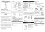
4.1.2 Components
The component image below shows a schematic of what the inside of a heat pump looks like. There may be differences
between different versions.
1
14
16
10
12
4
3
5
17
15
18
21
2
6
7
19
20
8
8
9
11
13
Figure 5. The components are shown above
Symbol explanation
1 Water heater, 180 litres 12 Drying filter
2 Return pipe sensor, heating system 13 Expansion valve
3 Evaporator, insulated 14 Hot water temperature sensor (displays maxi-
mum temperature)
4 Reversing valve 15 Control panel for control equipment
5 Supply line sensor 16 Electrical panel
6 Heating system circulation pump 17 Compressor
7 Auxiliary heating, immersion heater 18 Low pressure switch
8 Brine in 19 Operating pressure switches
9 Heating system supply line 20 High pressure switch
10 Brine out 21 Condenser with primary side drain
11 Brine pump brine system
12 – Installation instructions VMBMA702

4.2 DHP-H Opti Pro
4.2.1 Dimensions and connections
The brine pipes can be connected on either the left or right-hand sides of the heat pump.
110
1845 (±10)
455
596
528
300
440
40±10
1
2
610
80
4
7
8
6
5
9
3
Figure 6. Dimensions and connections
Symbol explanation
1 Brine in, 28 Cu
2 Brine out, 28 Cu
3 Heating system supply pipe, 22 Cu: 4-10 kW, 28 Cu: 12-16 kW
4 Heating system return pipe, 22 Cu: 4-10 kW, 28 Cu: 12-16 kW
5 Expansion pipe, 22 Cu
6 Hot water line, 22 mm
7 Cold water line, 22 mm
8 Lead-in for supply, sensor and communication cables
9 Safety valve for temperature and pressure (only applies to certain
models)
Installation instructions VMBMA702 – 13

4.2.2 Components
The component image below shows a schematic of what the inside of a heat pump looks like. There may be differences
between different versions.
1
2
3
8
4
5
6
7
9
10
11
12
13
14
16
18
17
22
21
23
19
20
15
Figure 7. Components
Symbol explanation
1 Water heater, 180 litres 13 Drying filter
2 Return pipe sensor, heating system 14 Hot water temperature sensor (displays max-
imum temperature)
3 Evaporator, insulated 15 Control panel for control equipment
4 HGW shunt valve 16 Electrical panel
5 Supply pipe sensor, heating system 17 Compressor
6 Heating system circulation pump 18 Low pressure switch
7 Auxiliary heating, immersion heater 19 Operating pressure switches
8 Brine out 20 High pressure switch
9 Heating system supply line 21 Condenser with primary side drain
10 Brine in 22 De-superheater
11 Brine pump brine system 23 HGW sensor
12 Expansion valve
14 – Installation instructions VMBMA702

4.3 DHP-C
4.3.1 Dimensions and connections
The brine pipes can be connected on either the left or right-hand sides of the heat pump.
110
1845 (±10)
455
596
528
300
440
40±10
2
1
610
80
4
7
8
6
5
3
Figure 8. Dimensions and connections
Symbol explanation
1 Brine in, 28 Cu
2 Brine out, 28 Cu
3 Heating system supply pipe, 22 Cu
4 Heating system return pipe, 22 Cu
5 Expansion pipe, 22 Cu
6 Hot water line, 22 mm
7 Cold water line, 22 mm
8 Lead-in for supply, sensor and communication cables
Installation instructions VMBMA702 – 15

4.3.2 Components
The component image below shows a schematic of what the inside of a heat pump looks like. There may be differences
between different versions.
1
14
16
15
10
13
4
3
5
17
18
19
21
20
24
2
6
7
22
23
8
9
11
12
Figure 9. The components are shown above
Symbol explanation
1 Water heater, 180 litres
2 Return pipe sensor, heating system
3 Evaporator, insulated
4 Heat exchanger for cooling operation
5 Exchange valve cooling
6 Shunt cooling
7 Exchange valve, heating/hot water
8 Supply line sensor
9 Heating system circulation pump
10 Auxiliary heating, immersion heater
11 Brine in
12 Heating system supply line
13 Brine out
14 Brine pump, brine system
15 Expansion valve
16 Drying filter
17 Hot water temperature sensor (displays maximum tem-
perature)
18 Control panel for control equipment
19 Electrical panel
20 Compressor
21 Low pressure switch
22 Operating pressure switch
23 High pressure switch
24 Condenser with primary side drain
4.4 DHP-L, DHP-L Opti
4.4.1 Dimensions and connections
The brine pipes can be connected on either the left or right-hand sides of the heat pump.
16 – Installation instructions VMBMA702

1538 (±10)
455
596
690
40±10
110
528
300
440
1
2
610
80
3
5
4
Symbol explanation
1 Brine in, 28 Cu
2 Brine out, 28 Cu
3 Heating system supply pipe, 22 Cu: 4-10 kW, 28 Cu: 12-16 kW
4 Heating system return pipe, 22 Cu: 4-10 kW, 28 Cu: 12-16 kW
5 Lead-in for supply, sensor and communication cables
4.4.2 Components
The component image below shows a schematic of what the inside of a heat pump looks like. There may be differences
between different versions.
1
14
15
10
13
4
3
5
11
18
2
6
7
16
17
8
9
12
Figure 10. The components are shown above
Symbol explanation
1 Auxiliary heater, immersion heater on supply line 10 Expansion valve
2 Return pipe, heating system 11 Control panel for control equipment
3 Reversing valve 12 Brine in
4 Evaporator, insulated 13 Electrical panel
5 Heating system circulation pump 14 Compressor
6 Supply pipe sensor, heating system 15 Low pressure switch
7 Brine out 16 Operating pressure switches
Installation instructions VMBMA702 – 17

Symbol explanation
8 Brine pump brine system 17 High pressure switch
9 Drying filter 18 Condenser with primary side drain
4.5 DHP-A, DHP-A Opti
4.5.1 Dimensions and connections
The brine pipes can be connected on either the left or right-hand sides of the heat pump.
1845 (±10)
455
596
528
258
250
300
40±10
1
2
610
80
5
78
9
6
10
3
4
Figure 11. Dimensions and connections
Symbol explanation
1 Brine in, 28 Cu
2 Brine out, 28 Cu
3 Lead-in for supply, sensor and communication cables
4 Heating system supply pipe, 22 Cu: 6-10 kW, 28 Cu: 12 kW
5 Heating system return pipe, 22 Cu: 6-10 kW, 28 Cu: 12 kW
6 Expansion pipe, 22 Cu
7 Hot water line, 22 mm
8 Cold water line, 22 mm
9 Expansion outlet brine circuit, R25 int.
10 Safety valve for temperature and pressure (only applies to
certain models)
18 – Installation instructions VMBMA702
/