Page is loading ...

User Manual
iR-AI04-TR User Manual
This guide walks through important information about iR-Axxx-TR.
UM018014E_20201006

Table of Contents
1. Product Overview ................................................................................................... 1
2. Specifications .......................................................................................................... 2
Module Specification ..................................................................................... 2 2.1
Temperature Specification ............................................................................. 2 2.2
3. LED Indicators ......................................................................................................... 4
L.V LED ............................................................................................................ 4 3.1
RUN LED ......................................................................................................... 4 3.2
ERR LED .......................................................................................................... 4 3.3
STA LED ........................................................................................................... 4 3.4
4. Error Handling ......................................................................................................... 5
5. Wiring ..................................................................................................................... 6
6. Features .................................................................................................................. 7
Feature List ..................................................................................................... 7 6.1
Configurable Mode ........................................................................................ 7 6.2
Disconnection Detection ................................................................................ 8 6.3
User-Defined Temperature Table ................................................................... 8 6.4
Analog Input – Filter Frame Size .................................................................... 8 6.5
7. Registers .................................................................................................................. 9
8. iR-ETN Coupler Address Mapping......................................................................... 14
9. iR-COP Coupler Address Mapping ........................................................................ 16
10. Downloading User-Defined Temperature Table to a Module .............................. 18
Appendix:Creating User-defined Temperature Reference Tables ............................. 21

iR-AI04-TR User Manual
1
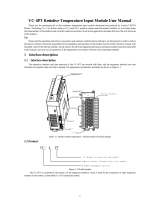
1. Product Overview
a
Terminal
b.c
Expansion Connector
81mm [3.19"]
109mm [4.29"]
27mm [1.06"]
Top View
Side View
iR-AXXX
Side View
Bottom View
a
b
c
27mm [1.06"]
iR-AQ04-VI
a

iR-AI04-TR User Manual
2
2. Specifications
Module Specification 2.1
Module Name
iR-AI04-TR
Number of Input Channels
4
Current Consumption
65mA@5VDC
Analog Power Supply
24 VDC(20.4 VDC~28.8 VDC)( -15%~+20%)
Specification
PCB Coating
Yes
Enclosure
Plastic
Dimensions WxHxD
27 x 109 x 81 mm
Weight
Approx. 0.12 kg
Mount
35mm DIN rail mounting
Environment
Protection Structure
IP20
Storage Temperature
-20° ~ 70°C (-4° ~ 158°F)
Operating Temperature
0° ~ 55°C (32° ~ 131°F)
Relative Humidity
10% ~ 90% (non-condensing)
Vibration Resistance
Conforms to EN 60068-2-6 / EN 60068-2-27
Connection
Cross-section
AWG 28-16
Certification
EMC Immunity
Conforms to
EN 55032: 2012+AC: 2013, Class A
EN 61000-6-4: 2007+A1:2011
EN 55024: 2010+A1: 2015
EN 61000-6-2:2005
Temperature Specification 2.2
Thermocouple
Type
Standard
Material
Temperature Range
J
IEC 60584
Fe-CuNi
-210 °C - 1200 °C
K
NiCr-Ni
-270 °C - 1370 °C
R
PtRh-Pt (Pt 13%)
-50 °C - 1760 °C
S
PtRh-Pt (Pt 10%)
-50 °C - 1760 °C
T
Cu-CuNi
-270 °C - 400 °C
E
NiCr-CuNi
-200 °C - 1000 °C
N
NiCrSi-NiSi
-270 °C - 1300 °C
B
PtRh-PtRh
200 °C - 1820 °C
C
W-Re(IEC 584)
0 °C - 2320 °C
L
DIN 43714
Fe-CuNi
0 °C - 900 °C
U
Cu-CuNi
-200 °C - 600 °C
TXK/XK(L)
P8.585-2001
Ni-9.5%Cr/Cu-44%Ni-13% Rh
-200 °C - -800 °C
TBP / BP(A)–1
W-5%Re/W-20%Re
0-2500
TBP / BP(A)–2
W-5%Re/W-20%Re
0-1800
TBP / BP(A)–3
W-5%Re/W-20%Re
0-1800
M
Cu-CuNi
-200-100
Conversion Time
100ms/channel
Resolution
0.1°C/0.1°F
Accuracy
± [0.4 % + 3°C ] Full Scale @ 25°C
± [0.6 % + 3°C ] Full Scale @ 0° ~ 55°C
RTD
Type
Temperature Coefficient
Temperature Range
Pt100
α: 0.00385
-200°C ~850°C
α: 0.00392
-200°C ~660°C
jPt100
JIS C 1609
-200°C ~600°C
PT200
α: 0.00385
-200°C ~850°C
PT500
α: 0.00385
-200°C ~850°C
Pt1000
α: 0.00385
-200°C ~850°C
α: 0.00392
-200°C ~660°C
LG-Ni1000
--
- 60~250°C
Ni100
0.00617
-100~180°C
Ni120
0.00672
-80~260°C
Ni1000
0.00617
-100~180°C

iR-AI04-TR User Manual
3
CU50
0.00428
-50°C ~150°C
CU100
0.00428
-50°C ~150°C
Conversion Time
200ms/channel
Resolution
0.1°C/0.1°F
Accuracy
± 0.2 % Full Scale@25°C
± 0.3 % Full Scale@0° ~ 55°C
Voltage
Type
Conversion Time
Resolution
±2V
100ms/channel
16bit
±1V
±500mV
±250mV
±125mV
±62.5mV
±31.25mV
Resistance
Type
Conversion Time
Resolution
0-5000Ω (0-30000)
200ms /channel
0.167Ω
0-500Ω (0-30000)
0.0167Ω
Isolation
500 VDC:(Analog / Digital)
Diagnose
Supply Voltage
Wire break
Overflow/underflow

iR-AI04-TR User Manual
4
3. LED Indicators
L.V LED 3.1
State
Description
OFF
24V power normal
Blinking
Detect 24V power
ON
24V power error
RUN LED 3.2
State
Description
OFF
No Power
Blinking
iBus initiating
ON
iBus working
ERR LED 3.3
State
Description
OFF
No error
Blinking
Analog channel error
ON
Unable to perform conversion
(Analog hardware error)
STA LED 3.4
State
Description
OFF
No error
Blinking
Conversion in progress

iR-AI04-TR User Manual
5
4. Error Handling
State
Description
Error Handling
L.V LED ON
24V power error
Check 24V power
L.V LED Blinking
Detect 24V power
Check 24V power
RUN LED is OFF
No Power
Check whether the coupler is
properly powered, or if module
malfunction occurs. Send the
malfunction unit for repair.
ERR LED ON
Unable to perform conversion
Hardware error, send the unit for
repair.
RUN LED Blinking
iBus initiating
Check whether the coupler is
functioning, if not, send the unit for
repair.
ERR LED Blinking
Channel conversion error
Check the error code to find out
whether the output value exceeds
allowable range.
Check the error code to find out
whether the channel is set to a
correct mode, or sensor
disconnection occurs, or output
value exceeds allowable range.

iR-AI04-TR User Manual
6
5. Wiring
When using Thermocouple, please short the M0- and L0- pins.

iR-AI04-TR User Manual
7
6. Features
Feature List 6.1
No.
Feature
Descriptions
1
Configurable mode (RTC / TC / Voltage / Resistance)
3
Diagnose
RTD
Thermocouple
5
User-Defined Temperature Table
6
Digital Filter
Configurable Mode 6.2
This module supports most of the thermocouple and RTC on the market. An input
channel can be configured as Voltage or Resistance mode.
Thermocouple
Type
Standard
Material
Temperature Range
J
IEC 60584
Fe-CuNi
-210 °C - 1200 °C
K
NiCr-Ni
-270 °C - 1370 °C
R
PtRh-Pt (Pt 13%)
-50 °C - 1760 °C
S
PtRh-Pt (Pt 10%)
-50 °C - 1760 °C
T
Cu-CuNi
-270 °C - 400 °C
E
NiCr-CuNi
-200 °C - 1000 °C
N
NiCrSi-NiSi
-270 °C - 1300 °C
B
PtRh-PtRh
200 °C - 1820 °C
C
W-Re(IEC 584)
0 °C - 2320 °C
L
DIN 43714
Fe-CuNi
0 °C - 900 °C
U
Cu-CuNi
-200 °C - 600 °C
TXK/XK(L)
P8.585-2001
Ni-9.5%Cr/Cu-44%Ni-13% Rh
-200 °C - -800 °C
TBP / BP(A)–1
W-5%Re/W-20%Re
0-2500
TBP / BP(A)–2
W-5%Re/W-20%Re
0-1800
TBP / BP(A)–3
W-5%Re/W-20%Re
0-1800
M
Cu-CuNi
-200-100
Conversion Time
100ms/channel
Resolution
0.1°C/0.1°F
Accuracy
± [0.4 % + 3°C ] Full Scale @ 25°C
± [0.6 % + 3°C ] Full Scale @ 0° ~ 55°C
RTD
Type
Temperature Coefficient
Temperature Range
Pt100
α: 0.00385
-200°C ~850°C
α: 0.00392
-200°C ~660°C
jPt100
JIS C 1609
-200°C ~600°C
PT200
α: 0.00385
-200°C ~850°C
PT500
α: 0.00385
-200°C ~850°C
Pt1000
α: 0.00385
-200°C ~850°C
α: 0.00392
-200°C ~660°C
LG-Ni1000
--
- 60~250°C
Ni100
0.00617
-100~180°C
Ni120
0.00672
-80~260°C
Ni1000
0.00617
-100~180°C
CU50
0.00428
-50°C ~150°C
CU100
0.00428
-50°C ~150°C
Conversion Time
200ms/channel
Resolution
0.1°C/0.1°F
Accuracy
± 0.2 % Full Scale@25°C
± 0.3 % Full Scale@0° ~ 55°C
Voltage
Type
Conversion Time
Resolution
±2V
100ms/channel
16bit

iR-AI04-TR User Manual
8
±1V
±500mV
±250mV
±125mV
±62.5mV
±31.25mV
Resistance
Type
Conversion Time
Resolution
0-5000Ω (0-30000)
200ms /channel
0.167Ω
0-500Ω (0-30000)
0.0167Ω
Isolation
500 VDC:(Analog / Digital)
Diagnose
Supply Voltage
Wire break
Overflow/underflow
Disconnection Detection 6.3
A channel alarm will be generated when input sensor disconnection is detected.
User-Defined Temperature Table 6.4
Apart from the temperature tables of common Thermocouple and RTD, users can
defined their own temperature reference tables so that even when the sensor type is
not in the built-in list, the user can still define corresponding temperature table and
use the temperature module to collect temperature values from the sensors.
Allowable ranges are: 0-500 ohm, 0-5k ohm.
Analog Input – Filter Frame Size 6.5
The Filter Frame Size can stabilize the signal by averaging sampled values, in order to
achieve better control.

iR-AI04-TR User Manual
9
7. Registers
No.
Description
Default
Read/Write
0
Channel 0 Mode
1
Read/Write
1
Channel 1 Mode
1
Read/Write
2
Channel 2 Mode
1
Read/Write
3
Channel 3 Mode
1
Read/Write
4
Channel 0 Scale Range Upper Limit
32000
Read/Write
5
Channel 1 Scale Range Upper Limit
32000
Read/Write
6
Channel 2 Scale Range Upper Limit
32000
Read/Write
7
Channel 3 Scale Range Upper Limit
32000
Read/Write
8
Channel 0 Scale Range Lower Limit
-32000
Read/Write
9
Channel 1 Scale Range Lower Limit
-32000
Read/Write
10
Channel 2 Scale Range Lower Limit
-32000
Read/Write
11
Channel 3 Scale Range Lower Limit
-32000
Read/Write
12
Channel 0 Filter Frame Size
5
Read/Write
13
Channel 1 Filter Frame Size
5
Read/Write
14
Channel 2 Filter Frame Size
5
Read/Write
15
Channel 3 Filter Frame Size
5
Read/Write
16
Error Code
0
Read
17
Command
0
Read/Write
18
Channel Detection
FFh
Read/Write
19
Celsius / Fahrenheit Setting
0
Read/Write
20
Channel 0 Temperature Offset
0
Read/Write
21
Channel 1 Temperature Offset
0
Read/Write
22
Channel 2 Temperature Offset
0
Read/Write
23
Channel 3 Temperature Offset
0
Read/Write
24
Channel 0 Maximum Value
0
Read
25
Channel 1 Maximum Value
0
Read
26
Channel 2 Maximum Value
0
Read
27
Channel 3 Maximum Value
0
Read
28
Channel 0 Minimum Value
0
Read
29
Channel 1 Minimum Value
0
Read
30
Channel 2 Minimum Value
0
Read
31
Channel 3 Minimum Value
0
Read
* Scale range setting is only available for Voltage mode.
* Temperature offset setting is only available for temperature mode.

iR-AI04-TR User Manual
10
Mode Setting
Value
Description
0
Close
1
Thermocouple
J
2
K
3
R
4
S
5
T
6
E
7
N
8
B
9
C
10
L
11
U
12
TXK/XK(L)
13
TBP / BP(A)–1
14
TBP / BP(A)–2
15
TBP / BP(A)–3
16
M
17
RTD
Pt100 -385
18
Pt100 -392
19
Pt1000-385
20
Pt1000-392
21
LG-Ni1000
22
Ni100
23
Ni1000
24
CU50
25
CU100
26
User-defined Temperature Table
27
Resistance
0-500Ω
28
0-5KΩ
29
Reserved
30
Reserved
31
Reserved
32
Reserved

iR-AI04-TR User Manual
11
33
Reserved
34
Reserved
35
Voltage
±2V
36
±1V
37
±500mV
38
±250mV
39
±125mV
40
±62.5mV
41
±31.25mV
42
RTD
JPt100
43
RTD
Pt200
44
RTD
Pt500
45
x
Reserved
46
RTD
Ni120
Voltage Mode connection at inputs:
V-
V+
M-
M+
L-
Voltage
( L- connected to V- contact with low-resistance)
Displaying digital value:
The temperature resolution for thermocouple and RTD is 0.1
degree. That is, 101.5 degrees = 1015 digital value.
In Resistance mode, the range of digital value is 0~30000. For
example, in 500 ohm mode, when the sensor detects 250 ohm, the
digital value obtained is 15000. When the sensor detects 100 ohm,
the digital value obtained is 6000.
In Voltage mode, the digital value is determined by the upper and
lower limit of the voltage range. In ±500mv mode, the upper limit
of the scale range is 32000 by default, and the lower limit is -32000
by default. When the sensor detects 500mv, the digital value
obtained is 32000, and when the sensor detects -500mv, the digital
value obtained is -32000. (Please note that scale range setting is
only applicable for Voltage mode.)

iR-AI04-TR User Manual
12
Scale Range Setting
This setting is only available for voltage mode. Please note that setting the upper
limit and lower limit to the same value will make the system use the default value.
Upper Limit
Lower Limit
maximum of range
minimum of range
Voltage
Setting
Description
Default
Upper Limit
Allowable range: -32768~32767
32000
Lower Limit
Allowable range: -32768~32767
-32000
Analog Input maximum / minimum value
This setting keeps on recording the maximum and minimum digital value. The record
can be cleared by giving a command (restart recording).
Setting
Description
Default
Input Max./Min. Value
Allowable range: -32768~32767
0
Error Code
Error Code
Description
0
Power error
1
Hardware error
2
Device isn’t calibrated
3
Reserved
4
Conversion cannot be performed.
5
cold junction compensation error
6
Reserved
7
Reserved
8
Input Channel 0 error
9
Input Channel 1 error
10
Input Channel 2 error
11
Input Channel 3 error

iR-AI04-TR User Manual
13
12
Reserved
13
Reserved
14
Reserved
15
Reserved
Command
Value
Description
0x0001
Restore factory default
0x0002
Reset the max./min. value of analog input channel 0
0x0003
Reset the max./min. value of analog input channel 1
0x0004
Reset the max./min. value of analog input channel 2
0x0005
Reset the max./min. value of analog input channel 3
0x0006
Reset the max./min. value of analog input channel 0-3
Celsius / Fahrenheit Setting
Value
Description
0
Celsius
1
Fahrenheit
Channel Detection
Bit
Description
Value
1
0
0
Analog Input Channel 0 Detection
Enable
Disable
1
Analog Input Channel 1 Detection
Enable
Disable
2
Analog Input Channel 2 Detection
Enable
Disable
3
Analog Input Channel 3 Detection
Enable
Disable
4-15
Reserved

iR-AI04-TR User Manual
14
8. iR-ETN Coupler Address Mapping
Module No.
Module Registers
iR-ETN Modbus Address
1
st
500
20000-20499
2
nd
500
20500-20999
3
rd
500
21000-21499
4
th
500
21500-21999
……
……
……
16
th
500
27500-27999
Example:
Module
Module Register
iR-ETN Modbus Address
iR-AQ04-VI
0# Channel 0 Output Mode
20000
1# Channel 1 Output Mode
20001
2# Channel 2 Output Mode
20002
3# Channel 3 Output Mode
20003
………
……..
16# Error Code
20016
………
……..
iR-AI04-VI
20# Channel 0 Input Mode
20520
21# Channel 1 Input Mode
20521
22# Channel 2 Input Mode
20522
23# Channel 3 Input Mode
20523
………
……..
iR-AI04-TR
0# Channel 0 Input Mode
21500
Module No.
Module Name
0
iR-ETN
1
iR-AQ04-VI
2
iR-AI04-VI
3
iR-AI04-TR
4
iR-AM06-VI

iR-AI04-TR User Manual
15
1# Channel 1 Input Mode
21501
2# Channel 2 Input Mode
21502
3# Channel 3 Input Mode
21503
………
……..
iR-AM06-VI
0# Channel 0 Output Mode
21500
1# Channel 1 Output Mode
21501
………
……..
20# Channel 0 Input Mode
21520
21# Channel 1 Input Mode
21521
22# Channel 2 Input Mode
21522
23# Channel 3 Input Mode
21523
………
……..
Module
Module Analog Channel
iR-ETN Modbus Address
iR-AI04-VI
Analog
Input
Channel 0 Digital Value
0
Channel 1 Digital Value
1
Channel 2 Digital Value
2
Channel 3 Digital Value
3
iR-AI04-TR
Channel 0 Digital Value
4
Channel 1 Digital Value
5
Channel 2 Digital Value
6
Channel 3 Digital Value
7
iR-AM06-VI
Channel 0 Digital Value
8
Channel 1 Digital Value
9
Channel 2 Digital Value
10
Channel 3 Digital Value
11
iR-AQ04-VI
Analog
Output
Channel 0 Digital Value
256
Channel 1 Digital Value
257
Channel 2 Digital Value
258
Channel 3 Digital Value
259
iR-AM06-VI
Channel 0 Digital Value
260
Channel 1 Digital Value
261
*Modbus Read Function Codes: 03h, 04h, 17h; Write Function Code: 06h, 10h, 17h

iR-AI04-TR User Manual
16
9. iR-COP Coupler Address Mapping
Module No.
Module Registers
Object Dictionary
Index
Sub-Index
1
st
127
3000h
01h-80h
2
nd
127
3001h
01h-80h
3
rd
127
3002h
01h-80h
4
th
127
3003h
01h-80h
……
……
……
01h-80h
16
th
127
300Fh
01h-80h
Example:
Module
Module Register
Index
Sub-Index
iR-AQ04-VI
0# Channel 0 Output Mode
3000h
01h
1# Channel 1 Output Mode
3000h
02h
2# Channel 2 Output Mode
3000h
03h
3# Channel 3 Output Mode
3000h
04h
………
……..
……..
16# Error Code
3000h
10h
………
……..
……..
iR-AI04-VI
20# Channel 0 Input Mode
3001h
15h
21# Channel 1 Input Mode
3001h
16h
22# Channel 2 Input Mode
3001h
17h
23# Channel 3 Input Mode
3001h
18h
………
……..
……..
Module No.
Module Name
0
iR-COP
1
iR-AQ04-VI
2
iR-AI04-VI
3
iR-AI04-TR
4
iR-AM06-VI

iR-AI04-TR User Manual
17
iR-AI04-TR
0# Channel 0 Input Mode
3002h
01h
1# Channel 1 Input Mode
3002h
02h
2# Channel 2 Input Mode
3002h
03h
3# Channel 3 Input Mode
3002h
04h
………
……..
……..
iR-AM06-VI
0# Channel 0 Output Mode
3003h
01h
1# Channel 1 Output Mode
3003h
02h
………
……..
………
20# Channel 0 Input Mode
3003h
15h
21# Channel 1 Input Mode
3003h
16h
22# Channel 2 Input Mode
3003h
17h
23# Channel 3 Input Mode
3003h
18h
………
……..
……..

iR-AI04-TR User Manual
18
10. Downloading User-Defined Temperature Table to a Module
Step 1. Connect iR-AI04-TR to iR-ETN, and then launch EasyRemotIO software to
find this module.
Step 2. Select iR-AI04-TR, and then select [Online] » [User Defined Temp. Table].
/