Eurotherm Action Pak AP4151 2000 Installation guide

Type
Installation guide

Eurotherm Action Pak AP4151 2000 is a versatile signal conditioner designed for accurate temperature measurement and conversion. It offers wide-ranging input options for various RTD types, enabling compatibility with different temperature sensors. The device features field configurability, allowing you to customize input and output ranges, including linear or non-linear temperature-to-current/voltage conversion. With its easy-to-use push-button calibration, you can quickly set the desired operational ranges and ensure precise measurements.

Eurotherm Action Pak AP4151 2000 is a versatile signal conditioner designed for accurate temperature measurement and conversion. It offers wide-ranging input options for various RTD types, enabling compatibility with different temperature sensors. The device features field configurability, allowing you to customize input and output ranges, including linear or non-linear temperature-to-current/voltage conversion. With its easy-to-use push-button calibration, you can quickly set the desired operational ranges and ensure precise measurements.

Mounting
All Action Paks feature plug-in installation. The AP4151-2000 uses
an 8-pin base, either the molded socket (M008) or the DIN rail socket
(MD08). An optional retaining spring (M801) is available if required
for the application.
Wiring Connections
Pin Signal
1 AC Power (Hot)
2 Shield (GND)
3 AC Power (Neutral)
4 RTD Input Return
5 RTD Input (-)
6 RTD Input (+)
7 Output (+)
8 Output (-)
Power Connections
Power is connected according to the table above. The unit supports
either 115VAC input (the default) or 230VAC input. If you need
230VAC input, jumpers, located next to the input transformer on the
base board, need to be changed according to the diagram below.
Diagnostic LEDs
Other than when executing the pushbutton calibration routine, the
LEDs blink under the following conditions:
GREEN: 2 Hz when the input is under range
8 Hz when the input is over range
RED: 2 Hz when the output is under range
8 Hz when the output is over range
An Under Range condition exists when the signal is lower than the
operational low value minus 6.25% of the operational span. An Over
Range condition exists when the signal is higher than the operational
high value plus 6.25% of the operational span.
Switch Settings
Figure 1. Calibration Flow Chart
RTD Input, Wide Ranging, Field Configurable,
Isolating Signal Conditioner
MODEL AP4151-2000
ACTIONPAK
TM
Installation and Calibration Instructions
Function SW1 SW2
RTD Type
1234567812345
Pt100-385

Pt200-385

Pt500-385

Pt1000-385

Pt100-3911
 
Pt200-3911

Pt500-3911

Pt1000-3911

Pt100-392

Pt200-392

Pt500-392

Pt1000-392

Ni100-618

Ni120-672

Cu9.035-427

No Linearization
Output
4-20mA
0-20mA
0-5V
0-10V

Reverse Out
Key: = ON or Closed
A voltage output short circuit can cause an under range condition
(RED blinking at a 2 Hz rate). A current output open circuit can cause
an over range condition (RED blinking at an 8 Hz rate). There could
be two or more LEDs blinking at the same time, which means the
module has more than one error condition present. Only when all error
conditions have been cleared will the LEDs retrurn to their normal
condition (Green ON, Red and Yellow OFF).
Calibration
For best results, calibration should be performed in the operating
environment, allowing at least one hour warm-up for thermal stability
of the system. If pre-calibration on a test bench is desired, an output
load equal to the input impedance of the devices connected to the
AP4151-2000 output is recommended, along with the warm-up period.
Note: Many applications do not require calibrating the output levels
and simply utilize the default operational ranges of the unit (0-5VDC,
0-10VDC, 0-20mA or 4-20mA). If the factory default calibration has
been changed, the last saved operational output values are utilized.
In those applications, the only calibration required is the operational
input values. Once the maximum and minimum input values have been
set, the Green and Red LEDs will be on. At this point, simply press
the CAL button rapidly 3 times and you will exit the calibration
routine without effecting the last saved calibration for the operational
output values.
1. Connect a resistance decade box (with 0.01 precision) to the input
(Pins 5 and 6). Jumper pin 4 to pin 5. Connect the output to a voltage
or current meter, depending on your application. Apply power and
allow the system to reach thermal equilibrium.
2. Hold down the pushbutton switch for 4 seconds. The Yellow and
Red LEDs should be on. Push the CAL button momentarily and the
Yellow and Green LEDs will be on. (From this point on, you can exit
the calibration procedure at any step without saving new data by
holding the CAL button for at least 4 seconds.)
3. Set the resistance to the value that matches your desired maximum
operational input temperature and push the CAL button. The Yellow
LED should now be on.
4. Set the resistance to the value that matches your desired minimum
operational input temperature and push the CAL button. The Green
and Red LEDs should now be on. If you do not wish to change the
output calibration, press the CAL button rapidly three times to exit
the calibration routine.
5. If you do wish to do a custom operational range for the output,
increase the resistance until the output is precisely at the desired
maximum level (e.g. 20.00mA) and push the CAL button. The Red
LED should be on.
6. Decrease the resistance until the output is precisely at the desired
minimum level (e.g. 4.00mA) and push the CAL button. All three
LEDs should now be on.
7. To finish calibration, push the button one final time. The calibration
data is now saved. The Green LED should be on if the input is within
the calibrated range.
Default Settings
Input: Pt-100, 0-500°C
Output: 4-20mA
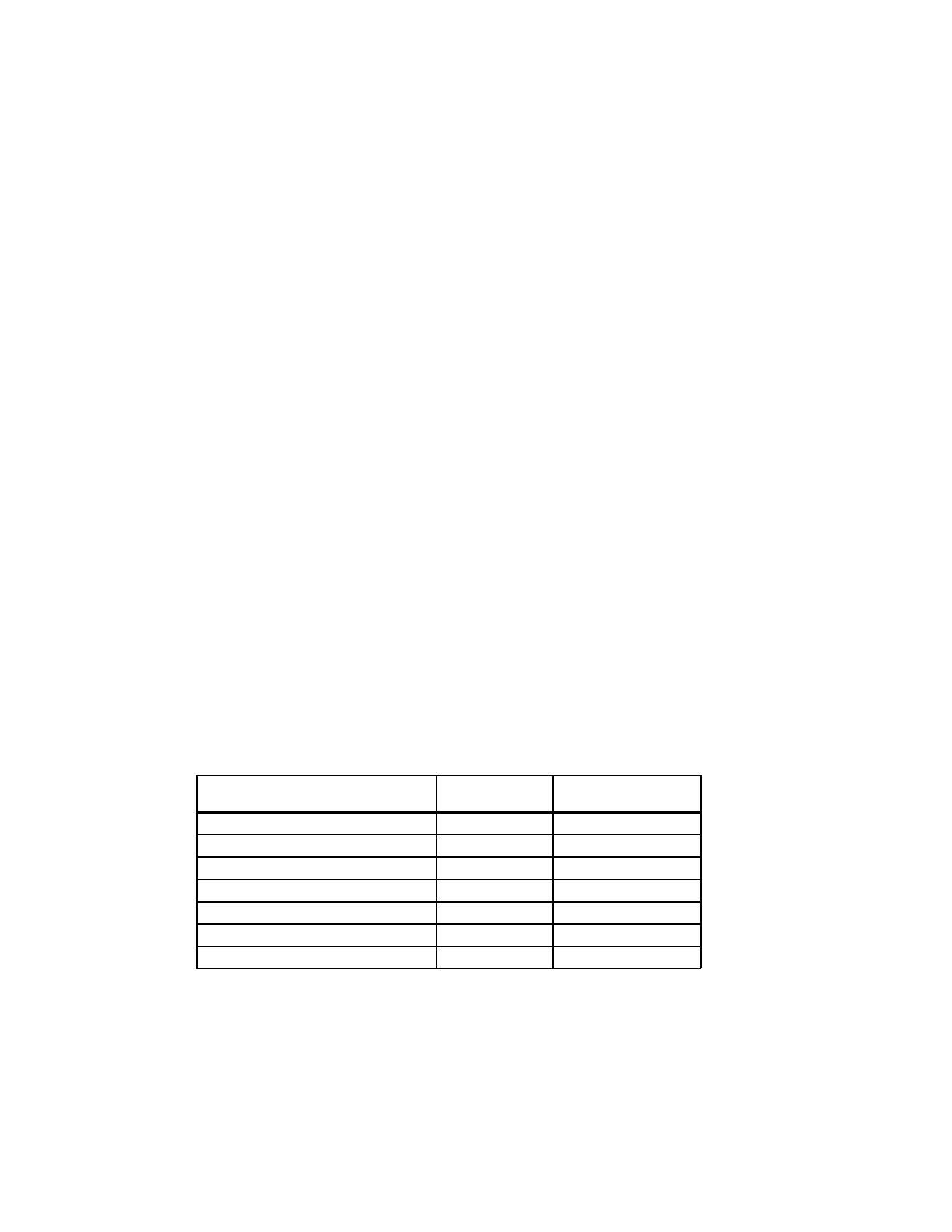
Table 1: AP4151 Input Limits
Input Type Input Range
Minimum
Recommended Span
Pt100 Ohm (0.00385, 0.003911, 0.00392) -200 to +870°C 100°C
Pt200 Ohm (0.00385, 0.003911, 0.00392) -200 to +870°C 100°C
Pt500 Ohm (0.00385, 0.003911, 0.00392) -200 to +870°C 100°C
Pt1000 Ohm (0.00385, 0.003911, 0.00392) -200 to +870°C 100°C
Ni100 Ohm (0.00618) -100 to +320°C 50°C
Ni120 Ohm (0.00672) -100 to +320°C 50°C
Cu9.035 Ohm (0.00427) -200 to +260°C 100°C
Dimensions
Dimensions are in millimeters (inches)
M008 (Track/Surface)
MD08 (DIN/Surface)
Mark III Case
Specifications
Input Ranges
See table 1
Leadwire Effect
< +/- 0.1% of maximum input temperature span, max.,
Leadwire Resistance (Maximum
/lead)
40% of RTD resistance
RTD Excitation Current
<25uA to 2.5mA depending on RTD type
Operating Modes
Direct: increasing input produces increasing output
Reverse: increasing input produces decreasing output
Output Ranges
0-20mA, 4-20mA, 0-5VDC, 0-10VDC (higher voltage to 15V @
3mA drive). Selectable between linear to temp or
Turn-Up/Turn-Down
75% (90% of span @ 0.5% linearity, 80% @ 0.15%)
Output Drive
0-20mA, 4-20mA ranges: 15V compliance (750 load maximum)
0-5V and 0-10V ranges: 10mA drive (1000 load minimum)
Output Accuracy
Current Outputs: + 0.1% of full scale, max.
Voltage Outputs: + 0.1% of full scale, max.
Stability
+ 100ppm (±0.01%) of full scale / °C, typical
Adjustments
Configuration: switch or pushbutton selectable
Pushbutton User Range: Pushbutton zero and span from
maximum to minimum specified in input range table.
Response Time
250mSec typical, 300mSec maximum.
LED Indicator
GREEN: RUN
On when unit is powered.
Flashes at a 2Hz rate when the input is under range by 6.25%.
Flashes at an 8Hz rate when the input is over range by 6.25%.
RED: OUTPUT
On while calibrating the output level.
Flashes at a 2Hz rate when the output is under range by 6.25%.
Flashes at an 8Hz rate when the output is over range by 6.25%.
YELLOW: INPUT
On while calibrating the input level.
Power Requirements
120/240VAC 50-400Hz, jumper selectable, 3W typical, 5W max.
Isolation
1500VDC, Input to Output to Power
Environmental
Operating Temperature: 0 to +60°C (32 to 149°F)
Storage Temperature: -20 to 85°C (-4 to 185°F)
Operating Relative Humidity: 15% to 95% RHNC @ 45°C
Non-operating Relative Humidity: 90% RHNC @ 65°C for 24 Hrs.
Agency Approvals
UL508 and UL recognized product
Eurotherm Controls
741-F Miller Drive
Leesburg, VA 20175-8993
703-443-0000
Factory Assistance
For additional information on calibration, operation and
installation contact our Technical Services Group:
703-669-1318
721-0851-00-E 12/04 Copyright© Eurotherm, Inc 2004
Action Instruments Barber-Colman Eurotherm Chessell Eurotherm Controls
  • Page 1 1
  • Page 2 2
  • Page 3 3
  • Page 4 4

Eurotherm Action Pak AP4151 2000 Installation guide

Type
Installation guide

Eurotherm Action Pak AP4151 2000 is a versatile signal conditioner designed for accurate temperature measurement and conversion. It offers wide-ranging input options for various RTD types, enabling compatibility with different temperature sensors. The device features field configurability, allowing you to customize input and output ranges, including linear or non-linear temperature-to-current/voltage conversion. With its easy-to-use push-button calibration, you can quickly set the desired operational ranges and ensure precise measurements.

Ask a question and I''ll find the answer in the document

Finding information in a document is now easier with AI