
User Manual
iR-ETN User Manual
This guide walks through important information about iR-ETN
UM018002E_20201208

Table of Contents
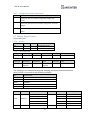
1. Product Overview ................................................................................................... 1
2. Specifications .......................................................................................................... 2
3. LED Indicators ......................................................................................................... 3
L.V LED ............................................................................................................ 3 3.1
IO RUN/ERR LED ............................................................................................. 3 3.2
ENET RUN/ERR ............................................................................................... 3 3.3
RJ45 ................................................................................................................ 3 3.4
4. RJ45 Interface ......................................................................................................... 4
5. Reset Button ........................................................................................................... 4
6. IP Address Setup ..................................................................................................... 4
Reset Button ................................................................................................... 4 6.1
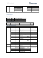
7. MODBUS Mapping .................................................................................................. 4
Bit Mapping .................................................................................................... 4 7.1
Register Mapping ........................................................................................... 5 7.2
TCP/IP Register ............................................................................................... 5 7.3
Device Information Register........................................................................... 5 7.4
iBus Information Register ............................................................................... 5 7.5
Module Information Register ......................................................................... 6 7.6
Module Register ............................................................................................. 6 7.7
Product Code List ........................................................................................... 7 7.8
Special Register .............................................................................................. 7 7.9
Life Guarding Register .................................................................................... 7 7.10
The Default Value ........................................................................................... 8 7.11
Device Error Code List .................................................................................... 8 7.12
Reading and Writing iR-PU01-P Objects ........................................................ 9 7.13
iR-PU01-P NMT Control Address .................................................................... 9 7.14
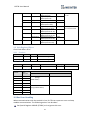
8. Modbus Mapping ................................................................................................... 9
iBus Information Register ............................................................................. 10 8.1
Digital Input Bit Mapping to Modbus .......................................................... 10 8.2
Digital Output Bit Mapping to Modbus ....................................................... 11 8.3
Analog Input Mapping to Modbus ............................................................... 11 8.4
Analog Output Mapping to Modbus ............................................................ 11 8.5
Module Register Mapping to Modbus ......................................................... 11 8.6
iR-PU01-P Variable Instance Mapping ......................................................... 11 8.7
9. EtherNet/IP ........................................................................................................... 14
Object List .................................................................................................... 14 9.1
Identity Objects ............................................................................................ 14 9.2

9.2.1 Service .......................................................................................... 14
9.2.2 Class Attributes ............................................................................ 14
9.2.3 Instance Attributes ....................................................................... 14
Manager Router Object ............................................................................... 14 9.3
9.3.1 Class Attributes & Instance Attributes ......................................... 15
Connection Manager Object ........................................................................ 15 9.4
9.4.1 Class Attributes & Instance Attributes ......................................... 15
Ethernet Link Object .................................................................................... 15 9.5
9.5.1 Services ........................................................................................ 15
9.5.2 Class Attributes ............................................................................ 15
9.5.3 Instance Attributes ....................................................................... 15
TCP/IP Interface Object ................................................................................ 15 9.6
9.6.1 Service .......................................................................................... 16
9.6.2 Class Attributes ............................................................................ 16
9.6.3 Instance Attributes ....................................................................... 16
9.6.4 Interface Status ............................................................................ 16
9.6.5 Configuration Control Attribute ................................................... 17
Module Register object ................................................................................ 17 9.7
9.7.1 Service .......................................................................................... 17
9.7.2 Class Attribute .............................................................................. 17
9.7.3 Instance Attributes ....................................................................... 17
iBus Object ................................................................................................... 18 9.8
9.8.1 Services ........................................................................................ 18
9.8.2 Class Attribute .............................................................................. 18
9.8.3 Instance Attributes ....................................................................... 18
Axis Register Object ..................................................................................... 19 9.9
9.9.1 Services ........................................................................................ 19
9.9.2 Class Attributes ............................................................................ 19
9.9.3 Instance Attributes ....................................................................... 19
10. iBus Error Handling ............................................................................................... 19
11. Power Consumption ............................................................................................. 21
12. Ethernet Cascading ............................................................................................... 21
13. EasyRemoteIO ....................................................................................................... 22
14. Connecting with CODESYS .................................................................................... 24
15. Connecting CODESYS with EasyBuilder Pro .......................................................... 28
Creating .xml File .......................................................................................... 29 15.1
16. Importing CODESYS Modbus TCP using EasyRemote I/O for iR-ETN .................... 32

iR-ETN User Manual
1
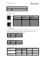
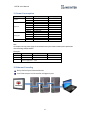
1. Product Overview
a
Reset Button
e
Expansion Connector
b
Ethernet Port LAN 1
c
Ethernet Port LAN 2
d
Power Connector
英文版 簡中版 日文版
Front View
Side ViewSide View
Top View
Bottom View
27mm [1.06"]
a
b
c
d
81mm [3.19"]
e
109mm [4.29"]
27mm [1.06"]
a
b
c
d
81mm [3.19"]
e
109mm [4.29"]
27mm [1.06"]
a
b
c
d
81mm [3.19"]
e
109mm [4.29"]
英文版 簡中版 日文版
Front View
Side ViewSide View
Top View
Bottom View
27mm [1.06"]
a
b
c
d
81mm [3.19"]
e
109mm [4.29"]
27mm [1.06"]
a
b
c
d
81mm [3.19"]
e
109mm [4.29"]
27mm [1.06"]
a
b
c
d
81mm [3.19"]
e
109mm [4.29"]

iR-ETN User Manual
2
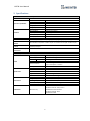
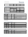
2. Specifications
Communication Interface Specifications
Model
iR-ETN
Expansion I/O Module
Number of Bus Terminals
Depends on Power Consumption
Digital Input Point
Max. 512
Digital Output Point
Max. 256
Analog Input Channel
Max. 64
Analog Output Channel
Max. 64
Indicators
ENET ACK (Green)
Device Status Indicator
ENET ERR (Red)
Device Error Indicator
L.V (Red )
Low Voltage Status Indicator
IO RUN (Green)
Module Status Indicator
IO ERR (Red)
Module Error Indicator
Data Transfer Rate
10/100 Mbps
Data Transfer Medium
4 x 2 twisted pair copper cable; category 3 (10 Mbps), category 5 (100 Mbps)
Distance Between
Stations
100 m between hub/switch and Bus Coupler or between Bus Coupler and Bus Coupler
Protocol
Modbus TCP/IP
EtherNet/IP Adapter
Max. Number of TCP/IP
Connections
8
Topology
line or star wiring
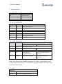
General Specification
Power
Power Supply
24 VDC (-15%/+20%)
Power Dissipation
Nominal 100mA @ 24VDC
Current for Internal Bus
Max 2A @ 5VDC
Current Consumption
220mA @ 5VDC
Electrical Isolation
Network to Logic : Isolation
Logic to Field power : Isolation
Back-up Fuse
≤ 1.6A Self-recovery
Specification
PCB Coating
Yes
Enclosure
Plastic
Dimensions WxHxD
27 x 109 x 81 mm
Weight
Approx. 0.15 kg
Mount
35mm DIN rail mounting
Environment
Protection Structure
IP20
Storage Temperature
-20° ~ 70°C (-4° ~ 158°F)
Operating Temperature
0° ~ 55°C (32° ~ 131°F)
Relative Humidity
10% ~ 90% (non-condensing)
Vibration Resistance
conforms to EN 60068-2-6 / EN 60068-2-27
Certification
EMC Immunity
Conforms to
EN 55032: 2012+AC: 2013, Class A
EN 61000-6-4: 2007+A1:2011
EN 55024: 2010+A1: 2015
EN 61000-6-2:2005

iR-ETN User Manual
3
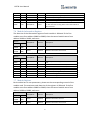
3. LED Indicators
L.V LED 3.1
L.V LED state
Description
OFF
24V power normal
Blinking
Detect 24V power
ON
24V power error
IO RUN/ERR LED 3.2
RUN LED
ERR LED
Description
OFF
OFF
Power off or no power
Blinking
OFF
IO initiating
Blinking
ON
IO initiation error
ON
OFF
IO working
ON
Blinking
IO module alarm
ON
ON
IO communication fault
Blinking
Blinking
Exceeding power limit or too many modules
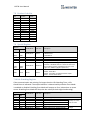
ENET RUN/ERR 3.3
Run LED
Err LED
Description
Modbus TCP
EtherNet/IP
OFF
OFF
Power off or no power
Blinking
OFF
Communicating
Pre-operational mode
ON
OFF
The device is in the OPERATIONAL state
OFF
ON
Hardware error,
communication fault
An irrecoverable error has
occurred.
ON
Blinking
Reset button is triggered
A recoverable error has
occurred.
ENET Run/ERR indicator can be set to Modbus TCP mode (default) or EtherNet/IP
mode. The communication address for Modbus TCP mode is 1013 (0x03F5 in Hex).
Communication mode setting: In “Config Data” set 0 to use Modbus TCP mode and 1
to use EtherNet/IP mode.
RJ45 3.4
Speed LED
OFF
Operating as a 10-Mbps connection
Green ON
Operating as a 100-Mbps connection

iR-ETN User Manual
4
LINK /ACT LED
OFF
No communication.
Blinking
There is activity on this port.
4. RJ45 Interface
RJ-45
Signal Name
Descriptions
1
TD+
Transmit +
2
TD-
Transmit +
3
RD+
Receive +
4
****
5
****
6
RD-
Receive -
7
****
8
****
Case
Shield
5. Reset Button
Press and hold the reset button for more than 2 seconds after the unit starts running
properly, and wait until ENET ERR LED blinks. The default parameters are shown
below, the settings will take effect after cold reset.
Item
Description
Default
1
IP Address
192.168.0.212
2
Netmask
255.255.255.0
6. IP Address Setup
Reset Button 6.1
Item
Description
Default
1
IP Address
192.168.0.212
2
Netmask
255.255.255.0
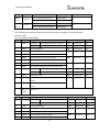
7. MODBUS Mapping
Bit Mapping
7.1
Parameter
Start address
Read/Write
Function Code
Dec
Hex
Digital Input
0~511
0000~
01FF
Read
2
800~863
0320~
035F
Read
3,23
Digital Output
0~511
0000~
01FF
Read
1

iR-ETN User Manual
5
0~511
0000~
01FF
Write
5,15
864~927
0360~
039F
Write
6,16,23
Register Mapping 7.2
Parameter
Start address
Read/Write
Function Code
Dec
Hex
Analog Input
0~255
0000~
00FF
Read
3,4,23
Analog Output
256~511
0100~
01FF
Read
3,23
Write
6,16,23
Registers
----------
Read
3,4,23
---------
Write
6,16,23
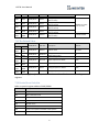
TCP/IP Register 7.3
Address
Read/Write
Data Size
Description
Dec
Hex
1000
03E8
Read
3word
(MAC-address).Ethernet physical address
If 00-0C-26-01-02-03, then 0x000C, 0x2601, 0x0203.
1003
03EB
Read/Write
2word
IP address
if 192.168.0.212, then 0xC0A8, 0x00D4.
1005
03ED
Read/Write
2word
subnet mask
if 255.255.255.0, then 0xFFFF, 0xFF00
1011
03F3
Read
1word
Number of TCP/IP connections
*TCP/IP Register Settings will take effect after cold reset or after giving Device Reset
Warm command.
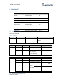
Device Information Register 7.4
Address
Read/Write
Data size
Description
Dec
Hex
3000
0BB8
Read
4word
Vendor name string 8 char: “weintek” (ASCII)
3004
0BBC
Read
1word
Product Code of iR-ETN is 0x0702
3005
0BBD
Read
1word
Firmware revision V1.23.4, 0x1234
3006
0BBE
Read
1word
Hardware revision V1.23.4, 0x1234
3007
0BBF
Read
1word
Power consumption unit mW
3008-
3023
0BC0-
0BCF
R/W
16word
Product name, default=“iR-ETN” (ASCII)
iBus Information Register 7.5
Address
Read/Write
Data size
Description
Dec
Hex
10000
2710
Read
1word
Slot 0 Product code (iR-ETN)
10001
2711
Read
1word
Slot 1 Module Product code
10001~
10016
2712~
2720
Read
1word
Slot 2~Slot 16 Module Product code

iR-ETN User Manual
6
10033
2731
Read
1word
Number of modules
10035
2733
Read
1word
Number of points of Digital Input
10036
2734
Read
1word
Number of points Digital Output
10037
2735
Read
1word
Number of Analog channels of Input register
10038
2736
Read
1word
Number of Analog channels of Output register
10045
273D
Read/Write
1word
0: ibus stops when one of the modules is disconnected.
1: ibus continues running when one of the modules is
disconnected.
Module Information Register 7.6
The data size of the information register of each module is 100word. If the first
module starts from address 30000 to 30099, then the second module starts from
address 30100 to 30199, and so on.
Address
Read/Write
Data size
Description
Dec
Hex
30000
~30099
7530~
7594
Read
100word
Module information of Slot 1
30100
~31599
7535~
7B6F
Read
100word
Module information of Slot 2~16
Ex: Module information of slot 1
Address
Read/Write
Data size
Description
Dec
Hex
30000
7530
Read
1word
Module product code, please see Product Code
List.
30001
7531
Read
1word
Module firmware version V1.23.4, value 0x1234
30002
7532
Read
1word
Module hardware version V1.23.4, value 0x1234
30003
7533
Read
1word
Power consumption unit mW
30038
7556
Read
1word
Number of points of Digital Input
30039
7557
Read
1word
Number of points Digital Output
30040
7558
Read
1word
Number of Analog channels of module
30041
7559
Read
1word
Number of Analog channels of module
Module Register 7.7
Each module has its own parameters; please see the corresponding manual of the
module used. The maximum total data size of the registers is 500word. If the first
module starts from address 20000 to 20499, then the second module starts from
address 20500 to 20999, and so on.
Address
Read/Write
Data size
Description
Dec
Hex
20000
~20499
4E20~
5013
Read
500word
Module information of Slot 1
20500
~27999
5014~
6D5F
Read
500word
Module information of Slot 2~16

iR-ETN User Manual
7
Product Code List 7.8
Item
Product
Code
1
iR-DI16-K
0154h
2
iR-DM16-P
0351h
3
iR-DQ16-P
0251h
4
iR-DM16-N
0352h
5
iR-DQ16-N
0252h
6
iR-DQ08-R
0243h
7
iR-AQ04-VI
0525h
8
iR-AI04-VI
0425h
9
iR-AM06-VI
0635h
10
iR-AI04-TR
0426h
11
iR-COP
0701h
12
iR-ETN
0702h
13
iR-PU01-P
0819h
Special Register 7.9
Address
Read/Write
Data size
Description
Dec
Hex
1013
03F5
Read/Write
1word
Indicator Mode:
0: Modbus TCP
1: EtherNet IP
5000
1388
Read
1word
Device Error code
5001
1389
Read
1word
Reserved
5002
138A
Read
1word
Slot1~16 of Module disconnect
5100~
5612
13EC~
15EC
Read/Write
512word
Setting the time filter (digital input, unit: ms). The
time filter is disabled when it is set to less than 5ms.
The time filter remains at 1000ms when it is set to
longer than 1000ms. (digital input 0-511)
6000
1770
Write
1word
Device Command
0x5269:Reset iBus
0x5250:Parameter to default without TCP/IP
0x5257:Device Reset Warm
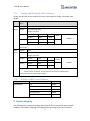
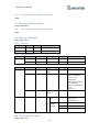
Life Guarding Register 7.10
If the communication was missing for longer than the Life Guarding Time, a Life
Guard Event is indicated. The output behavior is determined by whether Error Mode
is enabled or disabled. Enabling Error Mode will output an Error Value when an event
occurs. Disabling Error Mode will keep the last value (for both digital and analog).
Address
Read/Write
Data size
Description
Dec
Hex
6100
17D4
Read/Write
1word
Life Guarding Time, unit: ms, 0: Disabled
6101
17D5
Read/Write
1word
Digital Output Error Mode (bit15-0)
0:Keep last value
1:Error value
6102
17D6
Read/Write
1word
Digital Output Error Mode (bit31-16)
…..
…..
…..
…..
…..
6132
17F4
Read/Write
1word
Digital Output Error Mode (bit511-495)
6133
17F5
Read/Write
1word
Digital Output Error Value (bit15-0)
0:Low
1:High
6134
17F6
Read/Write
1word
Digital Output Error Value (bit31-16)

iR-ETN User Manual
8
…..
…..
…..
…..
…..
6164
1814
Read/Write
1word
Digital Output Error Value (bit511-495)
6165
1815
Read/Write
1word
Analog Output Error Mode
(channel 15-0)
0:Keep last value
1:Error value
6166
1816
Read/Write
1word
Analog Output Error Mode
(channel 31-16)
6167
1817
Read/Write
1word
Analog Output Error Mode
(channel 47-32)
6168
1818
Read/Write
1word
Analog Output Error Mode
(channel 63-48)
6169~
6232
1819~
1858
Read/Write
64word
Analog Output Error Value
(channel 63-0)
-32768~32768
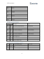
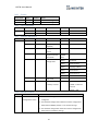
The Default Value 7.11
Address
Read/Write
Data size
Description
Default
Dec
Hex
3008-
3023
0BC0-
0BCF
Read/Write
16word
Product name
“iR-ETN”
5100~
5612
13EC~
15EC
Read/Write
512word
Setting the time filter
(Digital input 0-511)
0
6100
17D4
Read/Write
1word
Life Guarding Time
0
6101-
6132
17D4-
17F4
Read/Write
32 word
Digital Output Error Mode
0xFF
6133-
6164
17F5-
1814
Read/Write
32 word
Digital Output Error Value
0
6165-
6168
1815-
1818
Read/Write
4word
Analog Output Error Mode
0xFF
6169-
6232
1819~
1858
Read/Write
64word
Analog Output Error Value
0
※ After pressing [Reset] button, the Default Value will be filled into corresponding
registers.
Device Error Code List 7.12
Refer to special register address 5000/1388H
Bit Number
Description
Bit0
Low power alarm
Bit1
iBus initialization fault
Bit2
Hardware error
Bit3
Module lost connection
Bit4
Module alarm
Bit5
Number of iBus exceeds 16
Bit6
Power consumption exceeded at iBus system
Bit7~15
Reserved

iR-ETN User Manual
9
Reading and Writing iR-PU01-P Objects 7.13
Please see iR-PU01-P user manual for more information on index, sub-index, and
length.
R/W
Address
(Hex)
Description
Write
Object
0xFFF0
Index
0xFFF1
Sub-index (High Byte)
Length (Low Byte)
0xFFF2
Hi Byte
0x56
WORD
DWORD
Lo Byte
0x78
BYTE
0xFFF3
Hi Byte
0x12
Lo Byte
0x34
Sequentially writes data into 0xFFF0~0xFFF3. Data will be sent to iR-PU01-P when written
into 0xFFF3.
Read
Object
0xFFF4
Index
0xFFF5
Sub-index (High Byte)
Length (Low Byte)
0xFFF6
Hi Byte
0x56
WORD
DWORD
Lo Byte
0x78
BYTE
0xFFF7
Hi Byte
0x12
Lo Byte
0x34
Step1: Sequentially writes data into 0xFFF4~0xFFF5. Reading iR-PU01-P object starts when
data is written into 0xFFF5, and the data will be placed in 0xFFF6~0xFFF7.
Step 2: Read data of 0xFFF6~0xFFF7 Object.
iR-PU01-P NMT Control Address 7.14
NMT Address
State
Value
0xFFF8(65528)
Stop
0x0001
Operation
0x0002
Pre-operational
0x0080
Reset application
0x0081
Reset communication
0x0082
8. Modbus Mapping
The following is an example showing that when iR-ETN is connected with multiple
modules, the address mapping and input/output bit mapping can be as follows:

iR-ETN User Manual
10
item
Product
Slot#1
iR-DI16-K
Slot#2
iR-DQ16-P
Slot#3
iR-DM16-P
Slot#4
iR-DQ08-R
Slot#5
iR-AI04-VI
Slot#6
iR-AQ04-VI
Slot#7
iR-PU01-P
Slot#8
iR-PU01-P
Slot#9
iR-PU01-P
Slot#10
iR-PU01-P
iBus Information Register 8.1
Address
Description
Value
Dec
Hex
10000
2710
Slot 0 Product code (iR-ETN Device)
0x0702 (iR-ETN)
10001
2711
Slot 1 Product code (Module)
0x0154 (iR-DI16-K)
10002
2712
Slot 2 Product code (Module)
0x0251 (iR-DQ16-P)
10003
2713
Slot 3 Product code (Module)
0x0351 (iR-DM16-P)
10004
2714
Slot 4 Product code (Module)
0x0243 (iR-DQ08-R)
10005
2714
Slot 5 Product code (Module)
0243h (iR-AI04-VI)
10006
2714
Slot 6 Product code (Module)
0243h (iR-AQ04-VI)
10033
2731
Number of modules
10
10035
2733
Point of Digital Input
24
10036
2734
Point of Digital Output
32
10037
2735
Channels of register input
4
10038
2736
Channels of register output
4
Digital Input Bit Mapping to Modbus 8.2
Slot
Module
Bit offset (0x0000~0x0017)
Function Code
Slot#1
iR-DI16-K
0x0000~0x000F (Digital Input 0~15)
2
Slot#2
iR-DQ16-P
N/A
Slot#3
iR-DM16-P
0x0010~0x0017 (Digital Input 0~7)
2
Slot#4
iR-DQ08-R
N/A

iR-ETN User Manual
11
Digital Output Bit Mapping to Modbus 8.3
Slot
Module
Bit offset (0x0000~0x0027)
Function Code
Slot#1
iR-DI16-K
N/A
Slot#2
iR-DQ16-P
0x0000~0x000F (Digital Output 0~15)
5, 15
Slot#3
iR-DM16-P
0x0010~0x0017 (Digital Output 0~7)
5, 15
Slot#4
iR-DQ08-R
0x0018~0x001F (Digital Output 0~7)
5, 15
Analog Input Mapping to Modbus 8.4
Slot
Module
Description
Address
Function Code
Slot#5
iR-AI04-VI
Channel 0 analog input
0
3, 4, 23
Channel 1 analog input
1
Channel 2 analog input
2
Channel 3 analog input
3
Analog Output Mapping to Modbus 8.5
Slot
Module
Description
Address
Function Code
Slot#6
iR-AQ04-VI
Channel 0 analog output
256
6, 16, 23
Channel 1 analog output
257
Channel 2 analog output
258
Channel 3 analog output
259
Module Register Mapping to Modbus 8.6
Slot
Module
Description
Modbus Address
Module Register
Slot#5
iR-AI04-VI
Channel 0 Input Mode
22020
20
Channel 1 Input Mode
22021
21
Channel 2 Input Mode
22022
22
Channel 3 Input Mode
22023
23
……
……..
……
Slot#6
iR-AQ04-VI
Channel 0 Output Mode
22500
0
Channel 1 Output Mode
22501
1
Channel 2 Output Mode
22502
2
Channel 3 Output Mode
22503
3
……
……..
……
16# Error Code
22516
16
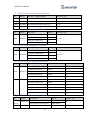
iR-PU01-P Variable Instance Mapping 8.7
Slot
Module
Description
Address
Function Code
Slot#7
(Axis 0)
iR-PU01-P
Axis 0 variable instance input
40000~40015
23
Axis 0 variable instance output
40500~40515
Slot#8
iR-PU01-P
Axis 1 variable instance input
40016~40031
23

iR-ETN User Manual
12
(Axis 1)
Axis 1 variable instance output
40516~40531
Slot#9
(Axis 2)
iR-PU01-P
Axis 2 variable instance input
40032~40047
23
Axis 2 variable instance output
40532~40547
Slot#10
(Axis 3)
iR-PU01-P
Axis 3 variable instance input
40048~40063
23
Axis 3 variable instance output
40548~40563
The following are examples explaining variable instance mapping. In these examples,
Axis 0 is used.
Axis 0 variable instance input:
Item
Address
Description
Data Type
Dec/Hex
1
40000
High Byte
Axis 0 Mode of Operation Display
USINT
Unsigned 8
Dec
Low Byte
Axis 0 Digital Input
BYTE
Unsigned 8
Hex
2
40001
Axis 0 StatusWord
UINT
Unsigned 16
Hex
3
40002
Axis 0 Position actual value (Lo word)
DINT
Signed 32
Dec
4
40003
Axis 0 Position actual value (Hi word)
5
40004
Axis 0 Velocity actual value(Lo word)
DINT
Signed 32
Dec
6
40005
Axis 0 Velocity actual value(Hi word)
7
40006
Axis 0 Position demand internal value(Lo word)
DINT
Signed 32
Dec
8
40007
Axis 0 Position demand internal value(Hi word)
9
40008
High Byte
Axis 0 Digital Output Status
BYTE
Unsigned 8
Hex
Low byte
Axis 0 Capture Channel Status
BYTE
Unsigned 8
Hex
10
40009
Axis 0 Error code
UINT
Unsigned 16
Hex
11
40010
Axis 0 2nd additional position actual value (Lo
word)
DINT
Signed 32
Dec
12
40011
Axis 0 2nd additional position actual value(Hi
word)
40012
~40015
Reserved
Axis 0 variable instance output:
Item
Address
Description
Data Type
Dec/Hex
1
40500
High Byte
Axis 0 Mode of Operation
USINT
Unsigned 8
Dec
Low Byte
Axis 0 Digital Output
BYTE
Unsigned 8
Hex
2
40501
Axis 0 Controlword
UINT
Unsigned 16
Dec
3
40502
Axis 0 Target Position (Lo word)
DINT
Signed 32
Dec
4
40503
Axis 0 Target Position (Hi word)
5
40504
Axis 0 Profile velocity (Lo word)
DINT
Signed 32
Dec
6
40505
Axis 0 Profile velocity (Hi word)

iR-ETN User Manual
13
7
40506
Axis 0 Target velocity (Lo word)
DINT
Signed 32
Dec
8
40507
Axis 0 Target velocity (Hi word)
9
40508
Axis 0 Profile acceleration (Lo word)
DINT
Signed 32
Dec
10
40509
Axis 0 Profile acceleration (Hi word)
11
40510
Axis 0 Profile deceleration(Lo word)
DINT
Signed 32
Dec
12
40511
Axis 0 Profile deceleration (Hi word)
40512
~40515
Reserved

iR-ETN User Manual
14
9. EtherNet/IP
Object List 9.1
Name
Object Type
Object Code (Hex)
Identity
Standard Object
01
Message Router
Standard Object
02
Assembly
Standard Object
04
Connection Manager
Standard Object
06
TCP/IP Interface
Standard Object
F5
Ethernet Link
Standard Object
F6
Module Register
Manufacturer Defined Object
70
iBus Object
Manufacturer Defined Object
71
AXIS Object
Manufacturer Defined Object
80~87
Identity Objects 9.2
Class Code: 01HEX
9.2.1 Service
Service Code
Class
Instance
Name
Value
0x01
●
●
Get Attribute All
0x05
X
●
Reset
0: Reset
0x0E
X
●
Get Attribute Single
9.2.2 Class Attributes
Instance ID
Attribute ID
Read/Write
Name
Data Type
Value
0
1
Read
Revision
UINT
1
2
Read
Max Instance
UINT
1
6
Read
Maximum ID Number
Class Attributes
UINT
7
7
Read
Maximum ID Number
Instance Attributes
UINT
7
9.2.3 Instance Attributes
Instance ID
Attribute ID
Read/Write
Name
Data Type
Value
1
1
Read
Weintek Vendor ID
UINT
1596
2
Read
Device Type-
Communications Adapter
UINT
12
3
Read
iR-ETN Product Code
UINT
1794
4
Read
Revision
Major
USINT
1
Minor
USINT
1
5
Read
Device State
WORD
6
Read
Serial Number
UDINT
7
Read
Product Name
STRING
“iR-ETN”
Manager Router Object 9.3
Class Code: 02HEX

iR-ETN User Manual
15
9.3.1 Class Attributes & Instance Attributes
None
Connection Manager Object 9.4
Class Code: 06HEX
9.4.1 Class Attributes & Instance Attributes
None
Ethernet Link Object 9.5
Class Code: F6HEX
9.5.1 Services
Service Code
Class
Instance
Name
0x01
●
X
Get Attribute All
0x0E
●
●
Get Attribute Single
9.5.2 Class Attributes
Instance ID
Attribute ID
Read/Write
Name
Data Type
Value
0
1
Read
Revision
UINT
4
2
Read
Max Instance
UINT
1
9.5.3 Instance Attributes
Instance ID
Attribute ID
Read/Write
Name
Data Type
Value
1
1
Read
Interface
Speed
UDINT
100:Speed 100M
2
Read
Interface Flags
DWORD
Bit 0 : Link Active
Bit 1 : Full Duplex
Bit 2~4 : Auto
negotiation
Bit 5 : Manual Setting
required Reset
Bit 6 : Local Hardware
Fault
Others : 0
3
Read
Physical
Address
6 USINTs
MAC address
1
11
Read
Interface Capability
Capability
Bits
DWORD
Interface capabilities,
other than
speed/duplex
Speed/
Duplex
Options
USINT
Number of elements
UINT
Interface Speed
USINT
Interface Duplex Mode
TCP/IP Interface Object 9.6
Class Code: F5HEX

iR-ETN User Manual
16
9.6.1 Service
Service Code
Class
Instance
Name
0x0E
●
●
Get Attribute Single
0x01
X
●
Set Attribute Single
9.6.2 Class Attributes
Instance ID
Attribute ID
Read/Write
Name
Data Type
Value
0
1
Read
Revision
UINT
4
2
Read
Max Instance
UINT
1
9.6.3 Instance Attributes
Instance ID
Attribute ID
Read/Write
Name
Data Type
Value
1
1
Read
Interface Status
DWORD
2
Read
Configuration
Capability
DWORD
0x00000020
3
Read
Configuration
Control
DWORD
0x00000000
4
Read
Physical Link Path
Size of Path
Padded-
PATH
00 00 20 F6 24 01
5
Read
Interface
Configuration
UDINT
IP address
UDINT
Network Mask
UDINT
Gateway Address
UDINT
Name Server
UDINT
Name Server 2
STRING
Domain Name
6
Read
Host name
STRING
iR-ETN
13
Read/Write
Encapsulation
Inactivity Timeout
UINT
0 = Disable timeout
1-3600 = timeout in
seconds
Default = 120
9.6.4 Interface Status
Bit
Name
Definition
0-3
Interface
Configuration Status
0 = The Interface Configuration attribute has not been
configured.
1 = The Interface Configuration attribute contains configuration
obtained from BOOTP, DHCP, or non-volatile storage.
2 = The interface configuration attribute contains configuration
obtained from hardware settings.

iR-ETN User Manual
17
9.6.5 Configuration Control Attribute
Value
Definition
0
The device shall use statically-assigned IP configuration
values..
1
The device shall obtain the interface configuration values via
BOOTP.
2
The device shall obtain the interface configuration values via
DHCP.
Module Register object 9.7
Class Code: 70HEX
9.7.1 Service
Service Code
Class
Instance
Service Name
0x01
●
X
Set Attribute Single
0x0E
●
●
Get Attribute Single
9.7.2 Class Attribute
Instance ID
Attribute ID
Read/Write
Name
Data Type
Value
0
1
Read
Revision
UINT
1
9.7.3 Instance Attributes
Instance ID
Attribute ID
Read/Write
Name
Data Type
Value
Slot#
Module
Register#
Read/Write
Module
Register#
INT
The following is an example showing the mapping of Instance ID and Attribute ID
when iR-ETN is connected to the following modules.
Slot
Module Name
Slot#1
iR-AI04-VI
Slot#2
iR-DQ16-P
Slot#3
iR-DM16-P
Slot#4
iR-DQ08-R
Slot#5
iR-AQ04-VI
Slot
Module
Description
Instance ID
Attribute ID
Module Register
Slot#1
iR-AI04-VI
Channel 0 Input Mode
1
20
20
Channel 1 Input Mode
21
21
Channel 2 Input Mode
22
22
Channel 3 Input Mode
23
23
………
………
………
Slot#5
iR-AQ04-VI
Channel 0 Output Mode
5
0
0
Page is loading ...
Page is loading ...
Page is loading ...
Page is loading ...
Page is loading ...
Page is loading ...
Page is loading ...
Page is loading ...
Page is loading ...
Page is loading ...
Page is loading ...
Page is loading ...
Page is loading ...
Page is loading ...
Page is loading ...
Page is loading ...
Page is loading ...
-
 1
1
-
 2
2
-
 3
3
-
 4
4
-
 5
5
-
 6
6
-
 7
7
-
 8
8
-
 9
9
-
 10
10
-
 11
11
-
 12
12
-
 13
13
-
 14
14
-
 15
15
-
 16
16
-
 17
17
-
 18
18
-
 19
19
-
 20
20
-
 21
21
-
 22
22
-
 23
23
-
 24
24
-
 25
25
-
 26
26
-
 27
27
-
 28
28
-
 29
29
-
 30
30
-
 31
31
-
 32
32
-
 33
33
-
 34
34
-
 35
35
-
 36
36
-
 37
37


Ask a question and I''ll find the answer in the document
Finding information in a document is now easier with AI
Related papers
-
weintek EasyRemoteIO User manual
-
-
-
-
-
-
-
-
-