
173 089 11.14
SINEAX TVD825 ENGLISH 4/4
SINEAX TVD825 ENGLISH 3/4SINEAX TVD825 ENGLISH 2/4SINEAX TVD825 ENGLISH 1/4
SINEAX TVD825
DC current/voltage
Isolating amplifi er/signal duplicator
1. Safety instructions
1.1 Symbols
The symbols in these instructions point out risks and have the following meaning:
Smooth and safe operation requires that these operating instructions be read
and understood!
Warning in case of risks.
Non-observance can result in malfunctioning.
Non-observance can result in malfunctioning and personal injury.
Information on proper product handling.
1.2 Intended use
• The purpose of the SINEAX TVD825 isolating amplifi er is to galvanically isolate input signals
from output signals, to amplify them and/or transform them to another level or another
signal type (current or voltage).
• The device is intended for installation in industrial plants and meets the requirements of
EN 61010-1.
• Manufacturer is not liable for any damage caused by inappropriate handling, modifi cation or
any application not according to the intended purpose.
1.3 Commissioning
• Installation, assembly, setup and commissioning of the device has to be
carried out exclusively by skilled workers.
• Observe manufacturer’s operating instructions. Do not operate the device
outside of the limit values stated in the operating instructions. Check all
electric connections prior to commissioning the plant.
• Safety measures should be taken to avoid any danger to persons, any
damage of the plant and any damage of the equipment due to breakdown
or malfunctioning of the device.
• Decommission the device if its safe operation is no longer possible (e.g. in
case of visible damages). Disconnect all connections. Send the device to
our plant or to one of our authorised service centres.
1.4 Repair work and modifi cations
Repair work and modifi cations shall exclusively be carried out by the manufac-
turer. In case of any tampering with the device, the guaranty and warranty claim
shall lapse. We reserve the right of changing the product to improve it.
1.5 Disposal
The disposal of devices and components may only be realised in accordance
with good professional practice observing the country-specifi c regulations
(applicable within the European Union and other European countries with a
separate collection system).
1.6 Transport and storage
Transport and store the devices exclusively in their original packaging. Do not
drop devices or expose them to substantial shocks.
2. Scope of delivery
1 Isolating amplifi er SINEAX TVD825
1 Operating instructions in German, French and English
3. General features
• Input of voltage, current, temperature (RTD, TC) or resistance
• Power supply of the sensor for current input (max. 17 V DC)
• Measurement on galvanically isolated output for voltage and active/passive current.
• Selection of input and output type, START/END for the selected input and output type by
means of DIP switches.
• Indication of available power supply and of alarm state via LED.
• Galvanic 4-way isolation (supply/ input / output 1 / output 2): 1500 V AC.
4.4 Environmental conditions
Operating temperature -10…+65 °C
Storage temperature -20…+85°C
Humidity 30...90 % at 40 °C (non-condensing)
Degree of pollution 2
Area of application Indoor areas up to 2000 m above sea level
4.5 Regulations
The device complies with
the following standards:
EN 61000-4-5 Class 2 (Surge protection of inputs, outputs/
power supplies)
EN 61000-6-4/2002 EN 61000-6-4/2002 (Electromagnetic inter-
ference, industrial environments)
EN 61000-6-2/2005 (Electromagnetic compatibility,
industrial environments)
EN 61010-1/2001 (Safety)
All circuits have to be insulated with double insulation against
circuits carrying hazardous voltage. The power supply transformer
has to comply with the specifi cations of EN 60742: Isolating and
safety transformers
5. Mounting instructions
The signal converter is designed to be mounted on rails according to DIN 46277.
Mounting of signal converter
on the rail
1. Place the signal converter onto the top
part of the rail.
2. Press the signal converter downwards.
Removing the signal converter
from the rail
1. Use a screwdriver (as shown in the
fi gure) as a lever.
2. Turn the signal converter downwards.
For optimum function and longevity, ensure adequate ventilation of the signal.
We recommend installation in vertical position. Avoid installing the signal
converter above devices generating heat. We recommend installing it at the
bottom of the switch cabinet.
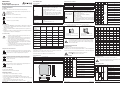
6. Installation instructions
6.1 Input selection
The input type is selected by setting the DIP switch group SW1 1 to 5.
Select the start of scale for the measuring input using DIP switches 6, 7 and 8 of switch group SW1.
Select the end of scale for the measuring input using DIP switches 6, 7 and 8 of switch group SW2.
Note for all tables:
The symbol indicates that the DIP switch is in ON position.
No entry means the DIP switch is in OFF position!
SW1: INPUT TYPES
12345678Type
Scale
START
Voltage input
Current input
Input of potentiometer (POT)
Input of thermocouple B (TC B)
Input of thermocouple E (TC E)
Input of thermocouple J (TC J)
Input of thermocouple K (TC K)
Input of thermocouple N (TC N)
Input of thermocouple R (TC R)
Input of thermocouple S (TC S)
Input of thermocouple T (TC T)
4. Technical data
4.1 General data
Power supply 10…40 V DC, 19…28 V AC, 50…60 Hz, max. 2,0 W; min. 0,5 W
Input
1 isolated independently parameterisable input for:
Current (input impedance 50 Ω): 0...20 mA via passive or active
connection (loop supply max. 25 mA at max. 17 V)
Voltage (input impedance 120 kΩ): 0...10 V
Potentiometer (input impedance > 5 MΩ): 1...100 kΩ (excitation
current 1 mA)
Thermocouple (input impedance > 5 MΩ): Type B,E,J,K,N,R,S,T
Thermo resistor: Type PT100, PT500, PT1000, NI100 (Excitation
current: 1.1 mA (PT100) and 0.11 mA (PT500, PT1000)
Input resolution 14 Bit
Sample rate Confi gurable: 16.66 ms (at 60 Hz) or 20 ms (at 50 Hz)
Response time Sample rate + 6 ms
Outputs
2 isolated, independently parameterisable outputs for :
Current (maximum load 600 Ω): 0...20 mA via passive or active
connection
Voltage (minimum load 20 kΩ): 0...10 V
Output resolution 14 Bit
4.2 Accuracy data
Error in relation to
maximum measur-
ing range
Basic accuracy
(at reference )
Temperature
infl uence
Linearisation
error
EMI
Voltage/current
input
0.1 % 0.01 % / °K 0.05 % <1 % (1)
Input
potentiometer
0.1 % 0.01 % / °K 0.1 % <1 %
Input TC:
E, J, K, N, T
0.1 % 0.01 % / °K 0.2 °C <1 % (1)
Input TC:
R, S
0.1 % 0.01 % / °K 0.5 °C <1 % (1)
Input TC:
B (2)
0.1 % 0.01 % / °K 1.5 °C <1 % (1)
Input RTD (3) 0.1 % 0.01 % / °K
0.02 % (if t>0 °C)
0.05 % (if t<0 °C)
<1 % (4)
Voltage / current
output (5)
0.1 % 0.01 % / °K 0.01 % <1 %
Reference
conditions
Ambient temperature 25 °C
Power supply 24 V
(1) Resistance infl uence of conductors 0.1 μV / Ω
(2) Output zero for t < 250 °C
(3) Type RTD: PT100, PT500, PT1000, NI100. All errors to be calculated for resistance value.
(4) Resistance infl uence of conductors 0.005 % / Ω, max. 20 Ω
(5) The values stated are to be added to the error of the input selected.
4.3 Installation data
Design Top-hat rail housing
Material PBT (black)
Connections Screw terminals 0.2...2.5 mm
2
Housing ingress
protection
IP20
Weight 200 g
Dimensions
100 mm
17,5 mm
112 mm
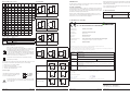
12345678Type
Scale
START
Input of thermo resistor (RTD) PT100 (2 conductors )
Input of thermo resistor (RTD) PT100 (3 conductors )
Input of thermo resistor (RTD) PT100 (4 conductors )
Input of thermo resistor (RTD) NI100 (2 conductors )
Input of thermo resistor (RTD) NI100 (3 conductors )
Input of thermo resistor (RTD) NI100 (4 conductors )
Input of thermo resistor (RTD) PT500 (2 conductors )
Input of thermo resistor (RTD) PT500 (3 conductors )
Input of thermo resistor (RTD) PT500 (4 conductors )
Input of thermo resistor (RTD) PT1000 (2 conductors )
Input of thermo resistor (RTD) PT1000 (3 conductors )
Input of thermo resistor (RTD) PT1000 (4 conductors )
SW1: Scale START for type slected
The table below lists the possible START and END values according to the input type selected.
678
Volt-
age
Cur-
rent
POT TC B (*) TC E TC J TC K TC N
0 V 0 mA 0% 0 °C -200 °C -200 °C -200 °C -200 °C
0.5 V 1 mA 10% 500 °C -100 °C -100 °C -100 °C -100 °C
1 V 2 mA 20% 600 °C 0 °C 0 °C 0 °C 0 °C
2 V 3 mA 30% 700 °C 100 °C 100 °C 100 °C 100 °C
4 V 4 mA 40% 800 °C 150 °C 200 °C 200 °C 200 °C
5 V 5 mA 50% 1000 °C 200 °C 300 °C 300 °C 300 °C
10 V 10 mA 60% 1200 °C 400 °C 500 °C 500 °C 500 °C
6 7 8 TC R TC S TC T PT100 NI100 PT500 PT1000
0 °C 0 °C -200 °C -200 °C -50 °C -200 °C -200 °C
100 °C 100 °C -100 °C -100 °C -30 °C -100 °C -100 °C
200 °C 200 °C -50 °C -50 °C -20 °C -50 °C -50 °C
300 °C 300 °C 0 °C 0 °C 0 °C 0 °C 0 °C
400 °C 400 °C 150 °C 50 °C 20 °C 50 °C 50 °C
600 °C 600 °C 100 °C 100 °C 30 °C 100 °C 100 °C
800 °C 800 °C 150 °C 200 °C 50 °C 200 °C 200 °C
6.2 Output selection
The output type is selected by setting the DIP switch group SW2 1 to 5.
Note: Set the DIP switches while module is powered down. This avoids electrostatic
discharges which might damage the module.
SW2: OUTPUT TYPES
12345678Type
Scale
END
Output 1: Voltage 0...10 V
Output 1: Voltage 0...5 V
Output 1: Current 0...20 mA
Output 1: Current 4...20 mA
Output 2: Voltage 0...10 V
Output 2: Voltage 0...5 V
Output 2: Current 0...20 mA
Output 2: Current 4...20 mA
Current output active
Current output passive


 1
1
 2
2


Gossen MetraWatt SINEAX TV815 User manual
GHM MU500L Owner's manual
WAGO 4AI RTD/TC/Strain Gauge Ex i User manual
Seneca K109UI User manual
Aim MyChron5S User manual
Omega DR-I3P-SIGNAL-CONVERTER Owner's manual
 Beckhoff EP3314 Documentation
