Page is loading ...

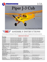
Your kit contains the following parts. Please check your kit for any missing or damaged parts before starting construction.
COMPLETE KIT PARTS LIST
1 Plan, Sheet 1 Decal Sheet 2 Blue Tissue
1 1/16" x 12" Landing Gear Wire 1 Molded Plastic Canopy 5 1/16" sq. x 18" Balsa Strip
27 3/32" sq. x 18" Balsa Strip 2 1/8" sq. x 18" Balsa Strip 2 3/32" x 1/4" x 18" Balsa Strip
1 3/16" x 1 3/4" Birch Dowel 1 Tail Wheel Assembly 1 Instruction Manual
1 Molded Plastic Propeller 1 Propeller Shaft 2 Brass Washer
1 Nylon Propeller Bearing 2 Plastic Wheels 1 3/16" x 60" Rubber Strip
2 Plastic Wheel Retainers 8 Laser Cut Sheets
Tools and Building Supplies
You will need the following items to assemble this model. You must read and follow all of the manufactures
instructions provided with these items!
-Glue CA, White Glue, Sigment or Ambroid all work well.
-Cutting Tools
A hobby knife with a #11 blade is used for general cutting. A single edge
razor blade is also a useful cutting tool.
-Clear Dope, Thinner & paint brush
-320 and 400 grit sandpaper
-Straight Pins
-Wax Paper
-Needle nose pliers
-1/4" & 1/16" Drill Bit
-Building Board

.
The first thing that you need to do is to identify and mark the part numbers on the laser cut parts using the drawings on the
following pages as a guide.
It is possible that several of the laser cut parts may not be completely cut through. If this is the case you can free the part from
the sheet quickly using an X-acto knife.
NOTE: The slight discoloration on the edges of the laser cut parts may be removed by lightly sanding the edges with 400 grit
sandpaper.

.
Building the Tail Surfaces
1.
Always cover the plan with wax paper before building any parts over the plan. This will prevent the parts from sticking to the
plan.
2.
Build the rudder over the plan using parts R-1, R-2 and R-3. The remainder of the structure is made from 3/32" sq. balsa
strip and 3/32" x 1/4" balsa strip as shown on the plan.
3.
Build the stabilizer over using parts S-1 and S-2. The remainder of the structure is made from 3/32" sq. balsa strip and 3/32"
x 1/4" balsa strip as shown on the plan.
4.
When the glue is dry, remove the rudder and stabilizer from the plan and sand the surfaces smooth and round the edges.
Test fit the stabilizer into the slot in the rudder. Now set these parts aside until needed later.
Building the Wing
Special Note:
The wing for this model is built in one piece. Because of the fact that most of the wing is elevated
above the plane you will find that most of the parts will not be pinned to the plan and most of the parts
will not line up with the plan. Once the main spar and the initial ribs are pinned to the plan, the
remaining parts will be assembled to allign to the previous parts using the plan as a guide only.
5.
The wing is built in one piece. The first step is to glue the main spar halves W-1 and W-2 together over the plan. When the
glue is dry, remove the main spar from the plan. Glue the wing tip parts W-11 and W-12 together. When the glue is dry,
remove from the plan.
6.
Pin the wing jig pieces WJ
-
1, WJ
-
2 and WJ
-
3 into position on the plan. Glue parts WJ
-
2 and WJ
-
3 together.
7.
Pin the main spar into position on the plan. The spar should be pinned to the building board as well as the wing jig near the
tips. Be careful to make sure that the spar is straight and not pulled forward or backwards at the tip. Carefully place the
outboard most rib W-3 into position on the spar and pin them to the plans aligning them 90 degrees to the main spar. They
may not line up exactly with the plan. Pin these two ribs to the plan and glue them to the main spar.

.
8. Carefully position all W-3 and W-4 ribs into position on the main spar. Use a small square to align the W-3 ribs 90 degrees
to the main spar and then pin them to the wing jig. The outboard face of the ribs W-4 should be flush with the edge of the
step in the wing jig. Pin the W-4 ribs to the wing jig. When you are sure that all of these ribs are aligned properly, glue them
to the main spar.
9.
Place ribs W-6, W-7, W-8, W-9 and W-10 into position on the main spar. Support the bottom of the spar with your finger
while pressing these ribs into position so you do not break the spar. Align these ribs 90 degrees to the main spar and pin
them to the wing jig. When you are sure that all of these ribs are aligned properly, glue them to the main spar.
10.
Working slowly and carefully cut, position, fit and pin the seven 3/32"x1/4" trailing edge pieces into position. The outboard
pieces should be left a little long. These will be trimmed to final size and shape after the wing tips are glued into position.
When you are happy with the fit of the trailing edge pieces you may glue them to the wing ribs.
11.
Repeat the above procedure to attach the 1/8" sq. leading edges to the wing assembly.
12.
Carefully pin the wing tips into position and glue them to the main spar, the leading edge and the trailing edges.
13.
Glue the W-5 ribs together and position them on the wing assembly. Once they are in the proper position you may glue
them to the spar and the leading edge.
14.
Carefully cut, fit and glue the 1/16" sq. leading edge spars into position. Bevel the outboard ends to fit the angle of the wing
tips.
15.
Now that the wing assembly is complete, go back and add an extra fillet of glue to each rib where they attach to the main
spar. When all of the glue is dry you may remove the wing from the plan and trim the leading and trailing edges of the wing
tip. Now carefully sand the leading edges round and taper the trailing edges. Sand the remainder of the wing smooth.
16.
Use a 1/16" drill bit to drill a hole in the W-5 ribs for the removable landing gear wire. Put a small drop of CA glue into each
hole to harden the wood. When this glue is dry you can run the drill bit back into the hole to clear out any excess glue.
17.
Set the wing aside until it is time to fit the wing to the fuselage in a later step.
Building the Fuselage
18.
Pin parts F
-
1, F
-
2, F
-
3 and F
-
4 into position on the plan. Glue F
-
2 and F
-
3 together at the rear.
19.
Pin formers F-5, F-6, F-7, F-8, F-9, F-10, F-11, F-12, F-13 and F-14 into position. Formers F-5 and F-6 have a small "x" on
them to designate the top. All of these formers are to be aligned 90 degrees to the building board. When you are happy with
the position of these formers you may glue them into position.
20.
Carefully press the master stringer F-15 into position. The small "x" is on the front of this piece. Make sure that all of the
formers are still 90 degrees to the building board and then glue F-15 to the formers.
21.
Fit and glue the F-16 wing saddle into position. The top of this piece should be against F-15. The front should be on top of
former F-6 and the rear should rest on top of former F-16. Brush a small amount of hot water on the outside of the wing
saddle if needed to allow it to curl and contact the curved formers easier.
22.
Sand a bevel on the inside of the rear of part F-
17 and test fit it to the rear of the fuselage assembly. Once the proper fit has
been achieved you may glue F
-
17 into position.
23.
Cut, fit and glue the 3/32" sq. stringers into position on the fuselage. The top stringers between F-8 and F-
9 may be cracked
to allow proper alignment.
24.
When the glue is dry, remove the fuselage from the plan and add the pieces for the opposite side using the same sequence
that you used for the first side. Use care to maintain a straight assembly as you build the opposite side.
25.
Carefully sand the fuselage smooth. Cut away former F-14 in the area of the stabilizer slots in parts F-17. Cut away the
support legs on formers F-7, F-8, F-9 and F-10 as these tabs are no longer required and will interfere with the rubberband
motor after the model is finished. Now set the fuselage aside.

.
Building the Cowling
26.
Pin parts C-1 and C-2 into position on the plan.
27.
Pin formers C-3 and C-4 into position 90 degrees to the plan. The "x" on these formers marks the top. When they are
properly aligned you may glue them to C
-
1 and C
-
2.
28.
Glue part C
-
5 into position making sure that the formers maintain their 90 degree alignment to the plan.
29.
Cut and glue the 3/32" sq. stringers into position on the cowling.
30.
Carefully remove the cowling from the plan and build the opposite side.
31.
Build the removable nose block using pieces C-6, C-7, C-8 and C-9. Cut the motor drawing from the plan and glue it to the
front of C-6 during assembly.
NOTE: It is easier to glue the C
-
7 pieces together and sand the inside curve on them before gluing them to the front of C
-
6.
32.
Glue the cowling to the front of the fuselage and then sand the outside of the cowling and nose block to shape.
33.
Carefully drill the 1/4" dia. hole in the nose block for the plastic thrust bearing. Be sure to add the proper amount of right and
down thrust as you drill this hole. Use some scrap 3/32" sheet balsa to fill in between two of the stringers between formers
F-12 and F-13 as shown on the plan. Drill a 3/16" hole about 1/4" from the front end of these fillers to hold the dowel that
holds the rear rubber motor.
34.
Test fit the wing and stabilizer to the fuselage. Do not glue them to the fuselage at this time.
35.
Trim the canopy and test fit it to the fuselage.
Building the Wing Radiators
36.
Assemble the two wing radiators from the parts shown on the plan. Be sure that you build one left hand and one right hand.
37.
Carefully sand the two radiators and test fit them to the wing. They will be glued into position after the model is covered.
Covering The Model
38.
Sand the entire model with 320 grit sandpaper.
39.
Coat the outside edges of all parts with two coats of clear dope.
40.
Attach the tissue to the model with clear dope mixed 50/50 with thinner.
41.
Lightly mist the model with water to shrink the dope.
42.
Apply 2 coats of thinned clear dope to the entire model.
43.
Apply the decals to the model.
44.
Draw additional detail onto the model with a waterproof marker.
Final Assembly
45.
Glue the wing to the model.
46.
Glue parts F-6A, F-7A and F-9A into position.
47.
Fit and glue the 3/32" sq. stringers into position between F-6A and F-9A.
48.
Cover this area with tissue as you did on the rest of the model.

.
49.
Glue the stabilizer into position on the model.
50.
Glue the rudder into position on the model.
51.
Paint the framework on the canopy with plastic model paint and glue to the fuselage when the paint is dry.
52.
Glue the wing radiators to the model.
53.
Bend the landing gear wires to the shape shown on the plan. Assemble the wheels, paint them and then secure them to the
landing gear wire with plastic retainers.
54.
Press fit the landing gear to the model. Cover parts LG-1 with tissue and glue them to the landing gear wires.
55.
The landing gear doors LG-2 can be covered and glued to the model but should not be used if you are going to fly the
model with a landing gear removed.
56.
Assemble the tail wheel and glue to the fuselage.
57.
Assemble the propeller. Glue this assembly into the removable nose block
58.
Tie the rubber motor and install it along with the nose block. Retain the motor at the rear of the fuselage with the 3/16"
dowel provided.
59.
Balance the model at the position shown on the plan. If you plan to fly the model with the landing gear removed then
balance the model with the landing gear removed.
60.
Your Corsair is now complete.
Beginners Note
These instructions were written assuming that the builder has previous building experience. If this is your flrst model then
we recommend that you purchase a copy of the following book:
Rubber Powered Model Airplanes By: Don Ross
This excellent book covers basic building and flying procedures and provides valuable information about all aspects of
building and flying rubber powered model airplanes.
Safety Rules
1. Fly your model in a large open area that is free of obstructions, people or their property.
2. Do not fly your model in the vicinity of power lines, trees, streets or buildings.
3. Never try to retrieve any model stuck in power lines, in trees or on a roof or other high place.
Never run into the street to retrieve your model.
4. Position yourself at least 150' from spectators before launching model.
5. Never launch model directly at another person or other object.
6. Never stick your fingers into a spinning propeller. Do not try to stop a spinning propeller with
your hand or fingers. Never stick any object into a spinning propeller.
7. Fly your model only on calm days. Do not fly when the wind is blowing.
8. Get proper permission before retrieving your model from private property.

.
WARRANTY
Herr Engineering Corp. guarantees this kit to be free from defects in both materials and
workmanship at the time of purchase. This warranty does not cover any component damaged buy
use or modification. In no case shall Herr Engineering Corporation's liability exceed the original cost
of the purchased kit. Further Herr Engineering Corp. reserves the right to change or modify this
warranty without notice.
In that Herr Engineering Corporation has no control over the assembly or use, no liability shall be
assumed or accepted for any damage resulting from the use by the user during construction of the
kit or the use of the final user assembled product. By the act of building this kit and/or using the final
user assembled product, the user accepts all liability.
If the buyer and/or user is not prepared to accept all of the liability associated with this product, he is
advised to immediately return this kit in new and unused condition to the place of purchase for a full
refund.
©
Copyright SIG Mfg. Co., Inc.
SIG MFG. CO., INC............Montezuma, Iowa 50171
-
0520
LIMIT OF LIABILITY:
In use of our products, Sig Mfg. Co.'s only obligation shall be to replace such quantity of the product proven to be defective.
User shall determine the suitability of the product for his or her intended use and shall assume all risk and liability in connection
therewith.
/