Page is loading ...

Electronic
Autocollimator
CONEX-LDS
USER’S MANUAL

EDH0322En1041 — 12/18 ii
CONEX-LDS Electronic Autocollimator
Warranty
Newport Corporation warrants this product to be free from defects in
material and workmanship for a period of 1 year from the date of
shipment. If found to be defective during the warranty period, the product
will either be repaired or replaced at Newport’s discretion.
To exercise this warranty, write or call your local Newport representative,
or contact Newport headquarters in Irvine, California. You will be given
prompt assistance and return instructions. Send the instrument,
transportation prepaid, to the indicated service facility. Repairs will be
made and the instrument returned, transportation prepaid. Repaired
products are warranted for the balance of the original warranty period, or
at least 90 days.
Limitation of Warranty
This warranty does not apply to defects resulting from modification or
misuse of any product or part.
This warranty is in lieu of all other warranties, expressed or implied,
including any implied warranty of merchantability or fitness for a
particular use. Newport Corporation shall not be liable for any indirect,
special, or consequential damages.
by Newport Corporation, Irvine, CA. All rights reserved.
Original instructions.
No part of this document may be reproduced or copied without the prior
written approval of Newport Corporation. This document is provided for
information only, and product specifications are subject to change without
notice. Any change will be reflected in future publishings.
CAUTION
War ranty does not apply to damages resulting from:
•Incorrect usage:
–Different use from that intended by NEWPORT.
–Use of a cable different from the one supplied by NEWPORT.
–Use or storage in environmental conditions other than those
indicated.
– Poor maintenance of the equipment, in particular, scratches on the
front optic, excessive humidity, shocks to the body.
•Modification of the productor any part thereof.
CAUTION
Please return equipment in
the original (or equivalent)
packing.
You will be responsible for
damage incurred from
inadequate packaging if the
original packaging is not
used.
© 2018

iii EDH0322En1041 — 12/18
CONEX-LDS Electronic Autocollimator
Table of Contents
Warranty .................................................................................................................ii
EC Declaration of Conformity...............................................................................v
Definitions and Symbols.......................................................................................vi
Warnings and Caution .........................................................................................vii
1.0 — Introduction.................................................................................1
2.0 — Description ...................................................................................2
2.1 Equipment..................................................................................................2
2.2 Modes of Operation ..................................................................................3
Display or Measurement Mode ...............................................................3
Analog Output or Data Gathering Mode ................................................3
2.3 Dimensions ................................................................................................3
3.0 — Principle of Operation............................................................4
3.1 Autocollimation Principle ........................................................................4
3.2 Electronic Autocollimator........................................................................5
4.0 — Characteristics............................................................................7
4.1 Units of Measure .......................................................................................7
4.2 Specifications ............................................................................................7
4.3 Specification Limits ..................................................................................8
Calibration .................................................................................................8
Temperature..............................................................................................9
Distance......................................................................................................9
Aperture Adjustment................................................................................9
Low Reflectivity.........................................................................................9
Polarization Effects .................................................................................10
Periodic Verification of Calibration ......................................................10
5.0 — Starting the Equipment........................................................11
5.1 Set Up........................................................................................................11
Class II Laser Product.............................................................................11
Mounting Stability...................................................................................11
CONEX-LDS Supports.........................................................................12
Recommended Mirror and Mounts for Different Applications ....14
Wobble Measurements of Rotary Bearings ....................................14
Analysis of Structures........................................................................14
Vibration Tests...................................................................................14

EDH0322En1041 — 12/18 iv
CONEX-LDS Electronic Autocollimator
5.2 Electrical Connections ...........................................................................14
Grounding ................................................................................................15
Communication Mode ............................................................................15
5.3 Display or Measurement Mode .............................................................15
A
lignment Procedure..............................................................................17
5
.4 Gathering Angle Measurements Remotely ..........................................19
A
nalog Outputs Resolution vs. Gain ....................................................19
6.0 — Examples of Applications ...................................................20
7.0 — Maintenance ..............................................................................22
7.1 Sensor Maintenance ...............................................................................22
7.2 Cables .......................................................................................................22
7.3 Preventive Maintenance.........................................................................23
8.0 — Verification Kit (CONEX-LDS-VER)..................................23
8.1 Description ..............................................................................................23
8.2 Function ...................................................................................................23
8.3 Verification Procedure ...........................................................................24
9.0 — Commands ..................................................................................25
9.1 Introduction.............................................................................................25
9.2 Communication Settings ........................................................................25
9.3 State Diagram ..........................................................................................25
9.4 Command Syntax ....................................................................................26
9.5 Command Execution Time.....................................................................27
9.6 Command Set...........................................................................................27
10.0 — Connector Interfaces.............................................................53
10.1 RS-422 Connector for Communication .................................................53
10.2 Analog Outputs Connector for Data Gathering...................................53
Service Form .........................................................................................................55

v EDH0322En1041 — 12/18
CONEX-LDS Electronic Autocollimator
CONEX-LDS
Year
mark affixed: 2017
EU Declaration of Conformity
The manufacturer:
MICRO-CONTROLE Spectra-Physics,
9, rue du Bois Sauvage
91055 Évry CEDEX, FRANCE
Hereby declares that the product:
y Description: " CONEX-LDS "
y Function: Electronic Autocollimator
y Type of equipment: Electrical equipment for measurement, control and laboratory
use
–complies with all the relevant provisions of the Directive 2014/30/EU relating to electro-
magnetic compatibility (EMC).
– complies with all the relevant provisions of the Directive 2011/65/EU relating to RoHS2.
– was designed and built in accordance with the following harmonised standards:
y NF EN 61326-1:2013 « Electrical equipment for measurement, control and
laboratory use – EMC requirements – Part 1: General requirements »
y NF EN 55011:2010/A1:2011 Class A
y CEI 60825-1:2008 « Safety of laser equipment radiation »
– was designed and built in accordance with the following other standards:
y NF EN 61000-4-2
y NF EN 61000-4-3
y NF EN 61000-4-4
y NF EN 61000-4-6
Date : 16/05/2017
Hervé LE COINTE
Quality Director
MICRO-CONTROLE Spectra-Physics
Zone Industrielle
F-45340 Beaune La Rolande, France
DC2-EN rev:A
EC Declaration of Conformity

EDH0322En1041 — 12/18 vi
CONEX-LDS Electronic Autocollimator
Definitions and Symbols
The following terms and symbols are used in this documentation and also
appear on the product where safety-related issues occur.
General Warning or Caution
The exclamation symbol may appear in warning and caution tables in this
document. This symbol designates an area where personal injury or
damage to the equipment is possible.
The following are definitions of the Warnings, Cautions and Notes that may
be used in this manual to call attention to important information regarding
personal safety, safety and preservation of the equipment, or important
tips.
WA R NI N G
Warning indicates a potentially dangerous situation which can result in
bodily harm or death.
CAUTION
Caution indicates a potentially hazardous situation which can result in
damage to product or equipment.
NOTE
Note indicates additional information that must be considered by the
user or operator.
European Union CE Mark
The presence of the CE Mark on Newport Corporation equipment means
that it has been designed, tested and certified as complying with all
applicable European Union (CE) regulations and recommendations.
Warnings and Cautions
ATTENTION
This stage is a Class A device. In a residential environment, this device
can cause electromagnetic interference. In this case, suitable measures
must be taken by the user.

vii EDH0322En1041 — 12/18
CONEX-LDS Electronic Autocollimator
Warnings and Caution
WARNING
IN ORDER TO COMPLY WITH SAFETY STANDARDS CONCERNING THE
USE OF THIS EQUIPMENT, THE USER MUST TAKE THE FOLLOWING
PRECAUTIONS AND HEED THE WARNINGS THAT APPEAR LATER IN
THIS MANUAL.
CAUTION
The user must read the warnings in the CONEX-LDS User’s Manual
before operating the equipment
CAUTION: LASER SAFETY
The CONEX-LDS is a CLASS II LASER INSTRUMENT according to the
IEC60825-1 standard:
DO NOT STARE INTO BEAM
Max. Power <1 mW @ 670 nm
For safety reasons, using this instrument in a dark environment is NOT
recommended: The lower the level of light, the larger the diameter of
the eye's pupils allowing more of the laser beam to damage the retina.
This also reduces the energy level which can damage the retina.
RAYONNEMENT LASER
N
E PAS REGARDER DANS LE FAISCEAU
L
ASER RADIATION
D
O NOT STARE INTO BEAM
A
PPAREIL A LASER DE CLASSE 2
CLASS II LASER PRODUCT
P
<1 mW;
λ
= 670 nm
IEC60825
ATTENTION RAYONNEMENT LASER
EN CAS D'OUVERTURE, EXPOSITION
DANGEREUSE AU FAISCEAU
DANGER. LASER RADIATION
WHEN OPEN, AVOID
DIRECT EXPOSURE TO BEAM
Manufacturer:
Zone Industrielle
45340 Beaune-la-Rolande
France
Device
CONEX-LDS
S/N:
Manufactured:
Complies with CFR 21 Subchapter J

EDH0322En1041 — 12/18 viii
CONEX-LDS Electronic Autocollimator
W
ARNING:
Stop using the autocollimator if it emits smoke, it is particularly warm, it
has an abnormal smell, makes an abnormal noise, or it shows any other
u
nusual signs.
Do not put anything in the CONEX-LDS autocollimator, and do not spill
any liquid on the sensor.
I
f it is integrated in a machine, ensure there is sufficient cooling: leave
enough space for air flow or use heat extraction means.
Never open the CONEX-LDS sensor, as there are risks of short circuits
and optical losses. Opening the CONEX-LDS voids the warranty.
Do not connect anything to the CONEX-LDS other than the cables
supplied by NEWPORT.
Do not use the CONEX-LDS autocollimator if you have noticed that it is
not working correctly.
CAUTION: SAFETY REGULATIONS
Do not use the instrument in an explosive environment.
Make sure there is no liquid near the instrument.
Make sure that the instrument is not exposed to excessive humidity
(more than 85%).
Do not replace any part and do not modify the equipment in any way.
Should it require servicing or repairs send it back to a Newport service
center.
NEWPORT SHALL NOT BE HELD LIABLE IF THE ABOVE-MENTIONED
WARNINGS ARE NOT FOLLOWED.

1 EDH0322En1041 — 12/18
CONEX-LDS Electronic Autocollimator
Electronic Autocollimator
CONEX-LDS
1.0 —Introduction
This manual describes the operation and conditions necessary for the
proper use of the NEWPORT CONEX-LDS autocollimator.
It also provides the basic maintenance to keep the instrument in good
working order.
IMPORTANT
The CONEX-LDS autocollimator is an optical angle measuring
instrument. A calibration certificate is provided by Newport with every
new Conex-LDS purchase, as well as with any recalibration service done
by the factory. It provides the values of the parameters that are stored
in the memory of the controller so that the instrument gives accurate
measurements. BEFORE any measurement, the operator must make sure
that the correct parameters are loaded in memory. Refer to the
corresponding chapter to check or update the correct parameters or
modify the angular units.
RECOMMENDATIONS
Read Section 5.0, “Starting the Equipment” before connecting the
autocollimator.
NOTE
The CONEX-LDS Controller GUI, software drivers and manuals can be
downloaded from www.newport.com/CONEX-LDS.

EDH0322En1041 — 12/18 2
CONEX-LDS Electronic Autocollimator
2.0 —Description
The CONEX-LDS autocollimator is a compact and self-contained angle
m
easuring instrument. It measures the angular variations of a reflective
surface, a plane mirror for example, using the movement of the reflected
beam on its position sensing sensor.
A PC is required to display the angular readings of the CONEX-LDS via the
Controller GUI and also to record measurement data. A stand alone or PC
c
ard data acquisition unit can also be connected to the analog outputs. The
XPS Universal Motion Controller can also be used to gather data from the
CONEX-LDS, see Section 5.4. The CONEX-LDS Controller GUI can be
downloaded from www.newport.com.
This manual describes the use of the CONEX-LDS autocollimator for all its
modes of operation.
2.1 Equipment
The autocollimator is delivered in a protective case which
contains the following:
• A CONEX-LDS optical head (including controller).
• A calibration certificate.
• A 5 meter communication cable.
The power supply, CONEX-LDS-PS and the RS-422 to USB
adapter, CONEX-USB-RS422 are ordered separately.
Accessories and options can be ordered separately.
• 20-meter USB/RS-422 communication cable.
!
"
"
#
$
%
!
&
$
$
’
"
(
#
)
)
)
)
)
)
)
’
*
+
,
-
&
"
,
"
!
!
"
&
!
&
.
"
/
0
"
!
"
&
1
$
2
+
#
3
+
#
4
*
/ $
*
5
/
&
.
.
!
6
3
5
5
6
4
7
8
5
3
9
*
8
4
5
*
7
:
;
6
&
!
&
"
1
$
%
+
"
!
&
9
/
<
7
5
=
’
!
0
&
&
"
>
7
’
!
2
$
$
$
$
2
’
$
$
$
’
$
2
$
$
$
$
2
’
$
$
$
’
$

3 EDH0322En1041 — 12/18
CONEX-LDS Electronic Autocollimator
2.2 Modes of Operation
2.2.1 Display or Measurement Mode
W
hen linked to a computer, by USB or Ethernet to RS-422 connector cable,
the instrument communicates through ASCII commands. Refer to Chapter
9.0 for the description of mnemonic commands.
A
dedicated Controller GUI provides access to the global functions of the
instrument.
This Controller GUI has its own manual. Please refer to it for a proper use
of the CONEX-LDS.
Refer to chapter 5.2 of this manual for connections.
2.2.2 Analog Output or Data Gathering Mode
2 analog outputs are available. They provide two output voltages that are
proportional to the angular measurements of the qX or qY (pitch and yaw)
axes of the CONEX-LDS.
This mode enables:
• Connection to an analog acquisition chain (can be connected to the
analog input of the Newport XPS controller or other data acquisition
instruments).
• Graphical display of angular positions on an oscilloscope.
• Use of the CONEX-LDS autocollimator for analog control, mirror
correction for example.
These outputs are converted from the digital values calculated by the
CONEX-LDS.
2.3 Dimensions
NOTE
A minimum 100 mm bend radius is needed to relieve stress on the
connectors.
5.39
(137)
1.89
(48)
ø1.378
0
(35
0
)
-0.1
-0.004
ø1.496
-
0.0008
(38
-0.02
)
-0.1
-0.004
1.035”-40
THD
2.83
(72)
.35
(9)
SQR 1.57
(40)
.32
(8.1)
SQR 1.57
(40)
10.60
(269)
HOLE M3 THD
USABLE DEPTH: .12 (3)
FOR GROUNDING

EDH0322En1041 — 12/18 4
CONEX-LDS Electronic Autocollimator
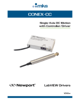
3.0 —Principle of Operation
3.1 Autocollimation Principle
The function of the CONEX-LDS autocollimator is based on the well known
p
rinciple of autocollimation.
A standard autocollimator uses a rear-illuminated cross light reticle A,
located behind the focal plane of a collimating lens B.
The light is projected to infinity which is reflected back to the instrument
with a plane reflecting mirror C.
The reflected beam is focused on the back of the focal plane of the
collimating lens. A beamsplitter D is used to recover 50% of the returned
light to form an image at the source reticle. Most instruments use a
measuring eyepiece E with a dark cross reticle to observe this
autocollimated image.
If the reflected image is coincident with the incident beam, the mirror is in
an autocollimating position. In this case, the last image of the source reticle
will superpose with the dark cross line of the eyepiece reticle.
For an angular movement of the mirror C, a lateral displacement of the
reflected image is observed at the focal plane of the collimating lens.
If the value of the focal length of the collimated lens is “F”, then the lateral
displacement will be:
DY = F
x tan(2Dq)
where Dq is the angular displacement of the mirror.
A
B C
DE
CONEX-LDS
Measurements = ∆θ
∆Y
F
(Output Objective Lens Focal Length)
X = F.tan(2.∆θ)
α = 1/2 arctan(∆Y/F)
F = 250 mm => ∆θ = 2000 µrad => ∆Y = 1 mm
Measurement
Mirror
CONEX-LDS
Objective
Lens
PSD Sensor
Laser Diode
Beam
Splitter
2.∆θ

5 EDH0322En1041 — 12/18
CONEX-LDS Electronic Autocollimator
This displacement can be measured in two ways, using the measuring
eyepiece:
• Mechanical angular movement Dα of the autocollimator in order to re-
center the reflected image inside the dark reticle (then Dq = Dα).
• Lateral movement of the cross reticle to measure DY (then Dq = DY/2F).
A
utocollimation is a common method to check and align optical elements,
such as laser cavities, Fabry-Pérot, and is used in all optical workshops to
measure prism characteristics and angular deviations. This is also a useful
tool for measuring table flatness. On the whole, these operations are done
manually.
3.2 Electronic Autocollimator
The advantage of the electronic autocollimator is that it automates angular
measurements.
Thus:
• It is possible to perform fast or slow measurements.
• It can average a large number of measurements.
• It enables automatic alignment.
For the CONEX-LDS autocollimator, the basic principles that are used to
obtain the values of angular displacements are as follows:
• The source reticle is a Laser diode.
• The measuring eyepiece is a position sensing device.
Laser Diode Specifications
•1mW laser diode; λ = 670 nm.
•5kHz modulation.
Position Sensing Device (PSD)
• 2 x 2 mm PSD sensing area: Delivers analog signals proportional to the
position (V
X
and V
Y
) of the beam.
• Sensitivity: 0.003 µrad/√Hz
The reflected beam is focused onto the XY position sensing device and
thus the two PSD signals are used to calculate the angular deviations.

EDH0322En1041 — 12/18 6
CONEX-LDS Electronic Autocollimator
Description
A Laser diode module F Alignment eyepiece
B Beamsplitter I G Magnifier
C Collimating lens H Position sensing device
D Mirror I Lighting LED (red)
E Beamsplitter II
One portion of the light is used for coarse visual alignment (visible laser
diode). A centered circle indicates the acceptable zone for automatic
recording.
The equivalent focal length, combining the collimating lens, C, and the
magnifier, G, is equal to 250 mm.
F
B
DC
A
G
I
H
E

7 EDH0322En1041 — 12/18
CONEX-LDS Electronic Autocollimator
4.0 —Characteristics
4.1 Units of Measure
The angular values are given in µrad, which is also the unit used for
c
alibration.
ANGULAR CONVERSIONS
1 mrad ~ 206 arc-seconds
1 µrad ~ 0.206 arc-second
1 arc-second ~ 4.85 µrad
1 mdeg ~ 17.45 µrad
These different units can automatically be displayed by changing the units
in the Controller GUI.
4.2 Specifications
4.2.1 CONEX-LDS Optical Head
• Wavelength 670 nm
• Peak power <1 mW (Class II laser)
• Pulse frequency 5 kHz
• Beam diameter 22.5 mm
• Beam direction <0.5 mrad in relation with autocollimator body
• Equivalent focal length 250 mm
• Beam divergence 0.1 mrad
• Ocular field ±15 mrad
• Measurement range ±2000 µrad
• Max. working distance 5 m
• Weight 2.4 lbs (1.1 kg)
4.2.2 CONEX-LDS Controller
• 2 x 16-bit analog outputs ±5 V = ±2000 µrad (gain sets to 1)
• Power supply 5 VDC (±5%), 0.25 A. Do not connect to a
DC power supply network.
• Measurement Distortion ±(5 ±0.02 x measurement) µrad
±5 µrad around 0 (i.e. ±2%)
• Measuring noise with maximum return
Resolution/dynamics 0.003 µrad/√Hz up to 2 kHz
• Max. measuring frequency 2000 Hz
• CONEX-LDS communication mode
RS-422/RS-485 4 wires full duplex without
handshaking (120 Ω resistor termination
included)

EDH0322En1041 — 12/18 8
CONEX-LDS Electronic Autocollimator
4.2.3 Environment
The performance of an autocollimator largely depends on the conditions
i
n which it is used:
• At a long working distance, the field of acquisition is reduced and the
o
ptical signal is disturbed by fluctuations in the air (see section 4.3.3).
•
With low reflectivity mirrors, the influence of electrical noise is fairly
substantial (see section 4.3.5).
• If the diameter of the reflecting mirror is greatly reduced, the accuracy
of the measurement may be affected (see section 4.3.4).
The above characteristics are given for an autocollimator used with a
mirror grater than or equal to 25.4 mm in diameter with reflectivity higher
than 80% at 670 nm and a working distance of less than one meter.
The operating limits of the CONEX-LDS autocollimator are as follows:
• Min. reflector return 2% at 670 nm
• Operating temperature +15 °C to +25 °C
• Humidity 10% to 80%
• Storage temperature -10 °C to +50 °C
The next section, “Specification Limits” describes the specifications of the
CONEX-LDS autocollimator according to the conditions of use.
4.3 Specification Limits
4.3.1 Calibration
A calibration certification comes with every CONEX-LDS. Parameters to
correct for linear errors are listed in the certificate. To view the stored
parameters in the unit, use the CD command.
Rotation around horizontal and vertical axes; Z: Beam Axis.
All these parameters are stored in the non-volatile memory of the
instrument after calibration (dedicated factory calibration bench).
These calibrating parameters were optimized to obtain the best
measurement results. We strongly recommend not to change these
parameters.
These parameters have been defined for the following conditions:
• Temperature 22 °C ±2 °C
• Mirror diameter ≥1 in. (25.4 mm)
• Reflectivity 80% at 670 nm
• Working distance 0.1 m
+
X
+
Y
B
a
c
k
wa
r
d
Be
a
m
+
Y
+
X

9 EDH0322En1041 — 12/18
CONEX-LDS Electronic Autocollimator
4.3.2 Temperature
The accuracy of the measurement is affected by changes in room
t
emperature.
The value measured is lower than the actual measurement when the
temperature drops.
4.3.3 Distance
When the working distance is increased to over 3 meters, the measurement
r
ange decreases.
With the distance D in meters, the maximum angular measurement range, A
m
ax
in µrad, which remains linear, is obtained by:
RG = ±6000 µrad/D (D >3 m)
Although the CONEX-LDS autocollimator uses a Laser source that is
perfectly collimated and of low divergence, the resulting calibration curves
may vary slightly for greater distances (>3 meters).
This does not apply to alignment applications (which returns a value 0.0).
Ambient air turbulence causes a considerable amount of noise on
measurements taken when the working distance increases. Turbulence in
the vicinity of the beam path should be minimized to obtain accurate
results.
4.3.4 Aperture Adjustment
MOTION OF REFLECTED BEAM
When the mirror diameter is smaller than the beam diameter, only a
part of the beam is returned into the CONEX-LDS head. If the mirror is
translated, the resulting motion of the reflected beam may generate a
measurement error.
To minimize the errors attributed to mirrors smaller than the beam
diameter, an aperture may be installed to reduce the output beam diameter
down to the mirror diameter. However, the usable measurement range
which is given relative to distance, decreases when the mirror diameter is
reduced.
4.3.5 Low Reflectivity
Using a CONEX-LDS autocollimator on low reflectivity mirrors does not
affect its linearity.
However, the measuring noise increases when the amount of light sent
back by the reflector is reduced. The multiplication factor due to noise is
obtained by:
K = (398 ÷ KS).(100 ÷ KR)
where:
• KS = Reflector-beam overlap in mm
2
(aperture adjusting).
• KR = Reflector reflectivity in %.
The usable measurement range, which is given relative to distance,
decreases as mirror reflectivity is reduced.

EDH0322En1041 — 12/18 10
CONEX-LDS Electronic Autocollimator
4.3.6 Polarization Effects
The CONEX-LDS autocollimator uses a circular polarized beam to reduce
t
he interference caused by internal components. The immediate result is
that the instrument is sensitive to the causes of depolarization.
We recommend not to use the autocollimator through birefringent
m
aterials (ex.: Plexiglas), or to use high incidence reflections on the
trajectory of the measuring beam. The error can quickly reach values of
100 µrad.
4.3.7 Periodic Verification of Calibration
In order to guarantee valid measurements during the CONEX-LDS
autocollimator life, periodic calibration must be carried out.
When used in a normal, fixed setup, under constant temperature and no
vibration conditions, annual calibration is recommended. Contact our
service team to schedule calibration, after which a new calibration
certificate will be provided .
In more rigorous conditions of use, it is recommended that the calibration
be checked more frequently. NEWPORT offers a verification kit,
(CONEX-LDS-VER) comprised of a certified calibrated wedge window and a
mechanical mount. The kit enables a quick verification of the CONEX-LDS
outputs, thus making sure that the instrument is properly calibrated (see
chapter: “Calibration Verification of the CONEX-LDS Autocollimator”).
This function is available through the CONEX-LDS Controller GUI.

11 EDH0322En1041 — 12/18
CONEX-LDS Electronic Autocollimator
5.0 —Starting the Equipment
5.1 Set Up
5.1.1 Class II Laser Product
NOTE
Beam Divergence: 0.1 mrad
Wavelength: 670 nm
Peak Power: <1 mW @ 5 kHz
5.1.2 Mounting Stability
The stability of the mirror mount and the support of the CONEX-LDS is
critical to minimize the variations in angular measurements. Depending on
the application, the CONEX-LDS can be mounted on a fixed rail or on
adjustable supports.
Newport supplies adjustable and stable supports to facilitate the setup of
the CONEX-LDS autocollimator to the reference mirror. For fixed mounting,
these components are supplied with the CONEX-LDS-VER, calibration
verification kit.
EXPOSURE AVOID
Laser radiation is emitted
from this aperture
CAUTION
CLASS II LASER RATED
FROM THIS APERTURE
22.5 mm
RAYONNEMENT LASER
NE PAS REGARDER DANS LE FAISCEAU
LASER RADIATION
DO NOT STARE INTO BEAM
APPAREIL A LASER DE CLASSE 2
CLASS II LASER PRODUCT
P <1 mW; λ = 670 nm
IEC60825

EDH0322En1041 — 12/18 12
CONEX-LDS Electronic Autocollimator
5.1.2.1 CONEX-LDS Supports
1
. Order the CONEX-LDS-SL support when tip/tilt adjustment is required.
–
Axis height: 75 mm
– qX and qY Angular range: ±2°
– Resolution: 200 µrad
– Sensitivity: 20 µrad
Adjustable Support – Axis height: 75 mm CONEX-LDS-SL
C
ONEX-LDS
4 HOLES ø.30 (7.5)
O
N 3.98
x 2
.0 (101
x 5
0.4)
4.72
(120)
RANGE: ±2°
BM17.04N
RANGE: ±2°
3.74
(95)
3.15
(80)
2.11
(53.5)
5.39
(137)
DIMENSIONS IN INCHES
(AND MILLIMETERS)
SL51 BODY
ø4.88
(124)
2.95
(75)
/