
1
Model 720 Dew Simulator Owner’s Manual - 20
6/22
Owner’s Manual
Model 720 Dew Simulator
Natural Dew Simulation Machine
Forage Harvester

2
(intentionally blank)

3
Model 720 Dew Simulator Table of Contents
Page
Introduction
5
Requirements
5
Safety
6
Safety Decal Definitions
6
Safety Decal Locations
7
Setup
8-12
Unloading the Machine
8
Connecting the Reel
9
Connecting Hoses
10
Connecting Perimeter Nozzle Hoses
10
Preparing the Water Supply Trailer
11
Hooking up Tractor, Dew Sim & Trailer Tank
12
Machine Setup
13-17
Installing Tines & Tips
13
Tine Assemblies
13
Tip Rate Chart – MW5 & MW11 Tips
14
Drive Chain
15
Trip Sections
16
Adjusting Trip Sections
16
Operating Perimeter Nozzles
17
Perimeter Nozzle GPM
17
Description of Electronic Valves and Sensors
18-19
2Way Valve
18
Warming Valve
18
Arm Switch
Flow Switch
19
19
Installing Controls
20
Wiring Diagram
20
Initial Operation
21-22
Turning on the Dew Simulator
21
Priming the System
21
Determining Operation Settings
22
Setting Pressures
22
Warming Up Systems
22
Operating
23-27
Control Box
23
Screen Definitions
23
Field Setup Screen Steps
24
Minimum and Maximum Levels
24
Diagnostic Screen
25
Main Screen
25-26
Heater #1 & #2
26
Arm Override
26
Operating Temp Status
27
Target PSI
28
Target GPM
28
Operation of the Dew Simulator
28
Removal of the Ground Drive Chain
29
Field Operation
29
Using Surfactant
29
Maintenance
30-32

4
Table of Contents (continued)
Maintenance Schedule
31
Preventative Maintenance
31
Maintenance Details
31
Heater Coil Descaling Procedure
31
Winterizing Procedures
32
Troubleshooting
33-36
Pin Outs
37-41
Parts Breakdown
42-65
Tine Assembly
42
Valve Assembly
42
Valve Exploded View
43
Valve Trip Assembly
43
Cross Tube Assembly & Trip Assembly
44
Cam Mount Assembly
45
Reel Dumbbell Assembly
45
X-Tube Bearing Assembly
46
Perimeter Nozzle Pump Assembly
46
Perimeter Nozzle Pump Feed
47
Perimeter Nozzle Assembly
47
Perimeter Nozzle supply Assembly
48
Reel Assembly
48
Torsion Axle
49
Lift Arm Assembly
49
Lift Arm Support Assembly
50
Hydraulic Cylinder Assembly
50
Limit Switch Assembly
51
Pump Intake Assembly
Pump Assembly
51
52
Pump Rear Assembly
53
Cart Frame
54
Front Bracket Assembly
55
Heater 1 (H1) Inlet & Outlet Assembly
55-56
Heater 1 (H1) Teeport Plug
56
Heater 2 (H2) Inlet & Outlet Assembly
56-57
Heater 2 (H2) Teeport Sensor
57
Flow Switch Assembly
58
Pump Discharge Front
58
Warmup Valve Assembly
59
Flow Meter Assembly
59
Heater Skid Assembly
60
Filter Bracket Assembly
Drive Hub Assembly
2” Y-Strainer/KZ Assembly
Chain Tensioner Assembly
61
61
62
62
Burner Motor Replacement Parts
63
Fire Extinguisher Assembly
63
Fuel Filter Assembly
64
Fuel Return & Fuel Outlet
64
Perimeter Nozzle Check Valve Assembly
64
Cart Electrical Assembly
65
Trailer Parts
65
Tractor Parts
66
Recommend Parts Stocking List
Hard Water Conditions
Notes
67
67
68-70
Warranty
71

5
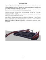
Introduction
The new Model 720 Dew Simulator allows for the precise addition of hot water mist to windrowed alfalfa. The
windrow will be as soft as if it had just received the ideal amount of dew. By spraying into the windrow prior to
baling, moisture is added to all of the plant material. The hot water mist softens the hay, giving the hay the
appearance and test of hay made with natural dew.
Right and Left sides are determined by facing in the direction of forward travel.
Requirements
• Tractor size and horsepower
o Min 80 horse power, Approximately 9,000lbs, 1000 rpm PTO
• Suggested trailer and tank
o Tandem axle 1,000 gallon water trailer
Below is an example of a water tank, Dew Simulator and tractor setup.

6
Safety
Carefully read all the safety signs in this manual and on the equipment before use. Keep signs clean and in
clear view. Replace missing or damaged safety signs. Replacement signs are available from your local
authorized dealer. Keep your Dew Simulator in proper working condition. Unauthorized modifications to the
system may impair the function and/or safety of the machine. Carefully read and understand all of the safety
signs before installing or servicing the 720 Dew Simulator.
Safety Decal Definitions
DCL-720-03
DCL-720-06
DCL-720-04
DCL-720-05
DCL-720-07
DCL-720-08
DCL-720-09
DCL-720-10
DCL-720-11
DCL-Yellow Reflector
2” x 9”
DCL-Red Reflector
2” x 9”

7
Safety Decal Locations

8
Setup
Unloading the machine
1. Unload the reel skid assembly and the cart assembly shown below and remove packaging. The reel skid is
designed to be handled from the front side (valves to right side) with pallet forks.
Reel Skid Assembly
Cart Assembly
2. Attach the cart assembly to a tractor and connect the hydraulic couplers
3. Turn the hydraulic valve to the unlocked position
Open
Closed

9
Connecting the Reel
1. Position the reel skid assembly next to the cart assembly. Lower the lift arm partially with the hydraulics
and position the reel so it is aligned, *side with valves goes towards the cart (below left).
Reel & Cart assemblies w/ lift arm being lowered
Reel & Cart assembly aligned
2. Align the holes in the lift arms with the mounting holes in the reel frame (above right).
3. Install the Pins & bushings (found in the cart parts box) as shown below. The bushings are located
between the inside of the reel frame brackets and the lift arm on the front and back side of the lift arm. After
the pins and bushings have been installed, install the roll pins in each end of the pivot pins. Lift the now
connected reel assembly slowly to remove the reel shipping skid, then raise into full transport position so
the lift arm is resting against the stops.

10
Connecting Hoses
Lower the reel from the transport position to the field operating position so both reel tires are on the ground.
Connect the stainless steel 3/4” water line attached to the swivel on the reel to the 45-degree elbow in the KZ
valve on the lift arm.
Connection location on the reel assembly
Above view of the water line reel connection
Connecting the Perimeter Nozzle Hoses
1. Locate the perimeter nozzle hoses coiled on the lift arm and remove the black zip ties holding them in
place.
2. Locate the black 1/2” hose that has the blue zip tie on the end. Attach this hose to the INSIDE nozzle
assembly and secure with the attached hose clamp. Hose may be trimmed to length but leave enough
slack to allow for movement of the reel frame when lifting into the transport position.
3. Locate the black 1/2” hose that has the red zip tie on the end. Attach this hose to the OUTSIDE nozzle
assembly by following the routing of the other 1/2” hose, then routing it through the rear of the inside
assembly and across the front of the reel frame to the outside nozzle assembly. Use the two P-clips
installed on the front of the frame to secure the hose. Trim hose to proper length and secure to outside
nozzle assembly with the attached hose clamp.

11
Preparing the Water Supply Trailer
The 720 Dew Simulator will require a water supply trailer (not included). The following step will explain the
installation of the supply, return fittings and hoses.
1. Install the 2” bulkhead connector in the bottom of the tank. Then install the 2” elbow (003-EL2020) fitting in
the bulkhead.
2. Attach the 2” hose (provided) to the 2” elbow fitting, route to front of trailer where the valve can be easily
accessed, cut hose to length, and install 2” valve assembly. From the remaining 2” hose, cut a section to
length that will run from the 2” valve assembly to rear of the machine. Install the 2” coupler fitting and
connect to the machine. Ensure hose is free to move when turning both directions with the machine.
Secure all connections with 2” hose clamps.
3. Install 1/2” stainless steel bulkhead in bottom of the tank, or front side towards the bottom of tank. Install
the steel 1/2” NPT x 3/4” Elbow (003-DSEL1234) and black green stripe hose. Route hose to rear of Dew
Simulator, cut hose to length, then attach to the aluminum coupler (002-2204B). Locate the ¾” On/Off
valve with hose barb fittings and attach to green stripe hose in an accessible location between the coupler
at the hitch and fitting at the bottom of the tank. Secure the green stripe hose to each fitting with the
provided hose clamps. *Note that water returning to the tank through this line will approach 200 F.

12
Hooking up Tractor, Dew Sim, and Trailer Tank
1. Connect the tractor to the cart assembly with a 1” draw pin (below, right).
2. Adjust the front hitch position to level the cart assembly to the tractor drawbar. The hitch can be moved up
or down as needed.
3. Connect the water trailer to the rear of the cart assembly with a 1” draw pin (shown above, left).
4. Adjust the rear hitch position to level the water trailer with the cart assembly by flipping the receiver hitch.
5. Connect the 2” valve/coupler from the water trailer to the coupler at the rear of the Dew Simulator.
6. Connect the ¾” green stripe valve assembly female coupler to the aluminum male coupler at the rear of the
Dew Simulator.
7. Connect the trailer lighting connector to the rear of the Dew Simulator. See trailer wiring schematic for
additional information.
2” Valve Coupler
Trailer Light
Connection
3/4” Aluminum Coupler

13
Machine Setup
Installing Tines & Tips
The reel assembly is shipped with 65 tines installed, each with a size MW11 tip (below left). There are 20 plugs
installed on the outermost holes of the reel assembly as well that can be removed using a 3/8” Allen wrench
and replaced with additional tines & tips (below right) if operating in wide windrows.
Reel Assembly
Tine / Tip Assembly
Tine Assemblies
Below are illustrations of the 8 and 9 Tine Cross Tube Assemblies located on the reel assembly. There are five
of each cross-tube assemblies (below).
Each cross tube has two holes with a plug in the tube. If the width of the windrow is wider than 45.5” covered
by the initial 65 tine & tip assembles installed, adding additional tips will be necessary. Remove the plugs using
a 3/8” Allen and add in the new tine & tip assemblies. Each additional set of 10 tips will increase the width of
coverage by 6.5” with a maximum increase of 13”. It is recommended to use Teflon tape or liquid thread
sealant on the threads and tighten to approximately 150ft/lbs.
Tip and tine assemblies can also be removed and replaced with plugs to reduce the coverage for thin, light, or
narrow windrows. **For two windrows that are raked together and are laying side by side forming a ‘valley’
between the two windrows, it may be beneficial to remove a row or two of tines in the center of the reel and
move them to the outside to prevent applying too much moisture to the lighter material between the two
windrows.
8-Tine Cross Tube Assembly (x5)
9-Tine Cross Tube Assembly (x5)
Tine
Tip

14
Tip Rate Chart
Use the chart below to determine the output (GPM) required by the dew simulator based on the field (ton/acre,
swath width, desired speed) and windrow (# of trips active) conditions. If tips need to be changed, a 7/16”
wrench or socket will be required to remove the tip currently installed. MW5 and MW11 tips, as well as
additional tines, can be purchased as spare parts from Harvest Tec. **Do not use a socket and impact driver
to remove or install tips as thread damage will occur.

15
Drive Chain
The Model 720 Dew Simulator comes with a drive chain installed, which allows the reel to be ground driven at
a rate where rotation of the reel matched forward movement. This gearing allows the tines to enter and exit the
windrow without significant disturbance or movement of the windrowed material. In heavier windrows, or
windrows that have been raked tightly or raked multiple times, it is possible to run the machine without the
drive chain installed, letting the windrow turn the reel in conditions where the tines are not exiting the windrow
cleanly without pulling excess stems into the wrap guard.
To reinstall the drive chain, lift chain idler upwards, install the chain, and seat the idler sprocket back onto the
chain. Chain tension can be adjusted by tightening or loosening the vertical 3/8” nut on top of the chain
tensioner bracket then locking it in place with the nut underneath the same bracket.
Chain idler/sprocket
Tension adjustment nut

16
Trip Sections
The trip sections shown (left) will determine when each cross
tube section will spray as the reel assembly rotates.
Adjusting Trip Sections
Adjust trip sections that are active based on windrow size/shape/and condition.
• If the windrow is tall and fluffy, adjust the sections so the tines turn on as soon as they enter the
windrow.
• If the windrow is shorter, shut off the leading trip sections so the tines do not turn on until they are about
to enter the hay.
• If less water is required to be added to the windrow, turn off rear trip sections so the tines don’t spray
the entire time they’re in the windrow.
• If there is moisture in the bottom of the windrow but the top 2/3 of the windrow is dry, turn off trip
sections at the bottom of the arc so the tines turn on as they enter the windrow, turn off for the bottom
1/3, then turn back on until they exit the windrow.
To activate, loosen the adjustment bolt on the backside of the valve plate with a 3/8” wrench. Rotate the reel so
the trip section is contacting a valve roller, slide the assembly up in the slot until the roller is pressed down,
then retighten the bolt. To deactivate sections, loosen the bolt, slide down in the slot away from the valves,
then tighten in position.
Trip active
Trip inactive

17
Adjusting Trip Sections (continued)
Front View Reel Trip Section
Reverse View Reel Trip Section
-Loosen and raise in slot, tighten to activate section
-Loosen and slide down in slot to deactivate section
Operation of Perimeter Nozzles
The perimeter nozzles are used to apply ambient temperature (non-heated) water in a course spray as a
supplement to the heated reel spray when evaporative conditions are high (due to extremely low humidity or
the presence of wind). The perimeter nozzle spray is selectable and controlled in the cab. It can be sprayed on
either side individually, or both sides at the same time. It can also be focused on the sides, or the tops and the
sides of the windrow by manually adjusting the angle and position of the nozzles.
Each perimeter nozzle operates off its own separate pump that is controlled by the switches and dial on the
perimeter nozzle cab controller. The toggle switch turns the control on, and the dial is used to increase or
decrease the flow to the nozzles. The two red switches control which pump is active. The perimeter nozzle
pumps will automatically turn off when the Arm Switch is not activated and the Arm Override is not activated
With the controller turned on, the two red switches will flash when the Arm Switch or Arm Override aren’t
active, and will show solid red when they are Active and the switch is turned on. The chart below provides an
estimate of the GPM for 1 and 2 pump operation at varying dial settings.
Perimeter Nozzle Controller Perimeter Nozzle GPM
Adjustment
Bolts

18
Description of Electric Valves and Sensors
2Way Valve
The 2way valve is located on the pressurized side of the pump on the lift arm.
When inactive, this valve is normally closed. In its normally closed state, fluid
from the outlet of the pump is returned to the tank. When it is open, fluid is
forced through the heaters then to the reel.
Warming Valve
The 2way warming valve is located towards the rear of the machine in between the heaters. The valve is on
the outlet side of heater #2 and is normally open. When Warmup Valve is activated on the main screen of the
control, it closes the 2way valve on the lift arm and allows flow that has gone through the heaters to be
returned to the supply tank. When the heaters are activated and heating water, the warming valve, when
opened, will allow heated water to be bypassed back to the supply tank until the water temperature reaches
200F. Once the water temp reaches 200F, the warmup valve will automatically close and shut off on the main
screen, forcing the heated, pressurized water out to the reel. The warmup valve is used for initial priming
(allowing bypass water back to tank) and for initial heating of the system so water does not need to be sprayed
on the ground until after the temperature has reached 200F. The warmup valve will also automatically open to
vent hot water back to the tank if the output temperature rises above 270F and the flow stops. When this
occurs, the green indicator light for the warmup valve will illuminate to indicate that the valve is in the open
position.

19
Arm Switch
The Arm Switch is located towards the front of the machine on the right side of the lift arm (shown below). This
is a mechanical switch that senses when the reel lift arm is in the field operating position. The arm switch is
active when it senses the lift arm. The arm switch must be active for the 2way valve to close, thus directing
flow out to the heaters. When the arm switch is deactivated (normally open), flow from the pump is recirculated
back to the tank.
For instance, if you are treating a windrow and raise the reel 12” off the ground, either when turning at the
headland or stopping in the windrow, the arm switch becoming deactivated will cause the 2way valve to open
and divert flow to the tank, shutting off flow to the reel. Similarly, for the heaters to run, the arm switch must be
active, so when the reel is raised the heaters will automatically turn off. Additionally, the system must also be
seeing a flow rate (GPM) from the flow meter before the heaters will run.
**For system priming and diagnostics, the arm switch can be overridden by the “ARM OVERRIDE” button on
the controller. Activating that button will cause the 2way valve to close and allow flow to go through the heaters
regardless of the lift arm position.
Flow Switch
The flow switch is a safety sensor located at the inlet to Heater #1 that detects flow going through the heaters.
When flow is detected, the internal circuit closes and allows the burner motors to run. When flow is absent and
the internal circuit is opened, all flow of electrical power to the burner motors is stopped.

20
Installing Controls
1. Connect 10 Pin extension harness (006-7722) to 10 pin connector on cart harness, route into tractor cab.
2. Connect 4 Pin extension harness (006-7717) to 4 pin connector on cart harness, route into tractor cab.
3. Mount Controller (006-7721) securely in cab with bracket and knobs on each side.
4. Mount Perimeter Nozzle Controller (006-7726) securely in cab with bracket and knobs on each side.
5. Connect 10 pin extension harness to Controller (006-7721)
6. Connect 4 pin extension harness to Perimeter Nozzle Controller (006-7726)
Wiring Diagram
Page is loading ...
Page is loading ...
Page is loading ...
Page is loading ...
Page is loading ...
Page is loading ...
Page is loading ...
Page is loading ...
Page is loading ...
Page is loading ...
Page is loading ...
Page is loading ...
Page is loading ...
Page is loading ...
Page is loading ...
Page is loading ...
Page is loading ...
Page is loading ...
Page is loading ...
Page is loading ...
Page is loading ...
Page is loading ...
Page is loading ...
Page is loading ...
Page is loading ...
Page is loading ...
Page is loading ...
Page is loading ...
Page is loading ...
Page is loading ...
Page is loading ...
Page is loading ...
Page is loading ...
Page is loading ...
Page is loading ...
Page is loading ...
Page is loading ...
Page is loading ...
Page is loading ...
Page is loading ...
Page is loading ...
Page is loading ...
Page is loading ...
Page is loading ...
Page is loading ...
Page is loading ...
Page is loading ...
Page is loading ...
Page is loading ...
Page is loading ...
Page is loading ...
Page is loading ...
Page is loading ...
-
 1
1
-
 2
2
-
 3
3
-
 4
4
-
 5
5
-
 6
6
-
 7
7
-
 8
8
-
 9
9
-
 10
10
-
 11
11
-
 12
12
-
 13
13
-
 14
14
-
 15
15
-
 16
16
-
 17
17
-
 18
18
-
 19
19
-
 20
20
-
 21
21
-
 22
22
-
 23
23
-
 24
24
-
 25
25
-
 26
26
-
 27
27
-
 28
28
-
 29
29
-
 30
30
-
 31
31
-
 32
32
-
 33
33
-
 34
34
-
 35
35
-
 36
36
-
 37
37
-
 38
38
-
 39
39
-
 40
40
-
 41
41
-
 42
42
-
 43
43
-
 44
44
-
 45
45
-
 46
46
-
 47
47
-
 48
48
-
 49
49
-
 50
50
-
 51
51
-
 52
52
-
 53
53
-
 54
54
-
 55
55
-
 56
56
-
 57
57
-
 58
58
-
 59
59
-
 60
60
-
 61
61
-
 62
62
-
 63
63
-
 64
64
-
 65
65
-
 66
66
-
 67
67
-
 68
68
-
 69
69
-
 70
70
-
 71
71
-
 72
72
-
 73
73


Ask a question and I''ll find the answer in the document
Finding information in a document is now easier with AI
Related papers


Other documents
-
 MacDon A30-D and A40-D User manual
-
 MacDon 5020 User manual
-
 MacDon 5010 User manual
-
 MacDon 912 and 922 Auger User manual
-
 MacDon 972 Harvest User manual
-
 MacDon A30-S, A30-D & A40-D User manual
-
RCI 186M User manual
-
Pottinger ROLLPROFI 3300 L SC CLASSIC Operating instructions
-
 MacDon 4000 User manual
-
 MacDon A40-D User manual


