Page is loading ...

P PA Model Transmissions and TPA Model PTO’s
Operation and Maintenance Instructions
Table of Contents
Introduction – PA Series ............................................................. 1
Description .................................................................................. 1
Lubrication ................................................................................... 1
Electronic Tachometer ................................................................. 1
Introduction – TPA Series ........................................................... 2
Description .................................................................................. 2
Lubrication ................................................................................... 2
Electronic Tachometer ................................................................. 2
Operating Instructions ................................................................. 3
Electronic Tachometer Frequency Reading ................................. 3
Maintenance ................................................................................ 3
Company 125 Hardman
Avenue South, South St.
Paul, Minnesota 55075
USA (651) 450-5000
Instructions subject to
change without notice.
F-1031, Section 2207 (Rev: 10/12/23)
Waterous Company, 125 Hardman Avenue South, South St. Paul, Minnesota 55075 USA (651) 450-5000
www.waterousco.com
Configurations
PA Model Transmissions
TPA Model Power Take-off's

F-1031, Section 2207
Page 1 of 3
Introduction - PA
The PA pump transmission is designed to drive Waterous mid-ship pumps off the
ten bolt, power take-offs (PTO) available on the left side of the Allison MD and HD
automatic transmissions. The largest capacity pump that can be driven with the
PA transmission depends on the maximum torque limits of the PTOs. The
manufacturers of the PTOs should be consulted for the fire truck heavy duty
power and speed ratings when selecting a pump/transmission combination to be
used. Several different speed increasing ratios are available with the PA
transmission to accommodate various PTO drive applications.
PA Series
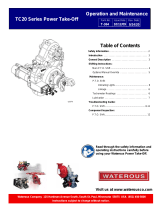
Description
The PA transmission body is made entirely of light weight cast aluminum alloy.
The shafts, sprockets and chain are steel. Power is transferred from the drive
shaft to the driven shaft via a high strength, involute form chain. This design
provides the smoothest and quietest transfer of power. Deep groove, anti-friction
ball bearings are used on the two shafts to provide smooth, long lasting service.
The drive shaft has a 1-1/2 inch SAE 10 spline. A two-piece driven shaft is used
when the PA is connected to a CM, CMU, CS or CSU pump. The two-piece
impeller shaft is separable between the pump and pump transmission, allowing
for easy removal of the transmission for major service. A one-piece driven shaft is
used when the PA is connected to CGG or CXV pump.
Lubrication
The bearings and drive chain are lubricated by a splash and passive lubrication
system. Lubrication is accomplished when spray from the chain collects in a
reservoir in the top of the case. The lubricant flows out of the reservoir onto the
inside surface of the chain. This ensures all pivoting components of the chain
receive lubrication.
Electronic Tachometer
An electronic tachometer connection protrudes from the tachometer housing at a
45° angle. This tachometer pick-up senses the drive shaft speed.
Pump
Mounting
Flange
Driven
Sprocket
Driven Shaft or
Pump Impeller
Shaft
Chain
Electronic
Tachomete
r Pick-up
Drive
Shaft
(Input)
Drive Sprocket

F-1031, Section 2207
Page 2 of 3
Introduction - TPA
The TPA pump transmission is designed to drive Waterous mid-ship pumps off
the ten bolt, power take-offs (PTO) available on the left side of the Allison MD and
HD automatic transmissions. The largest capacity pump that can be driven with
the TPA transmission depends on the maximum torque limits of the PTOs. The
manufacturers of the PTOs should be consulted for the fire truck heavy duty
power and speed ratings when selecting a pump/transmission combination to be
used. Several different speed increasing ratios are available with the TPA
transmission to accommodate various PTO drive applications.
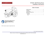
Description
The TPA transmission body is made entirely of light weight cast aluminum alloy.
The shafts, sprockets and chain are steel. Power is transferred from the drive
shaft to the driven shaft via a high strength, involute form chain. This design
provides the smoothest and quietest transfer of power. Deep groove, anti-friction
ball bearings are used on the two shafts to provide smooth, long lasting service.
The drive shaft has a 1-1/2 inch SAE 10 spline. The driven shaft has a 1-3/8 inch
SAE 10 spline.
TPA Series
Lubrication
The bearings and drive chain are lubricated by a splash and passive lubrication
system. Lubrication is accomplished when spray from the chain collects in a
reservoir in the top of the case. The lubricant flows out of the reservoir onto the
inside surface of the chain. This ensures all pivoting components of the chain
receive lubrication.
Electronic Tachometer
An electronic tachometer connection protrudes from the tachometer housing at a
45° angle. This tachometer pick-up senses the drive shaft speed.
Driven Sprocket
Chain
Drive Shaft
(Input)
Drive Sprocket

F-1031, Section 2207
Page 3 of 3
Operating Instructions
Since the PA and TPA transmissions are designed to be driven by a PTO, refer to
the instruction manual supplied with the PTO or to the apparatus manufacturer's
manual for specific information.
Electronic Tachometer Frequency Reading
The pulse generator in the PA and TPA chain drive transmissions have 10 teeth.
The frequency (Hz) reading from the tachometer sensor should be multiplied by 6
to obtain revolutions per minuted (rpm).
Hz x 6 = RPM
Maintenance
1. Check fluid level monthly by seeing if fluid is visible using the sight plug or by
removing fluid level plug. The fluid should be level with bottom of hole.
CAUTION
Low or excessive fluid may cause transmission damage.
If fluid level is low, locate source of leak and repair. If fluid level is high, loosen
fluid level plug until fluid drops to proper level. If excessive water drains out,
change fluid and determine source of water leakage, and repair.
2. Change fluid and clean the breather annually or after each 100 hours of
operation, whichever comes first. Fluid can be added thru the fluid level hole
or by removing the breather and adding fluid thru this opening. Use automatic
transmission fluid (ATF) that meets the requirements of DEXRON III, or
MERCON V.
Amount required if system is drained and refilled:
Vertical Mounting: 1-1/4 Quarts (Approximately)
Horizontal Mounting: 3/4 Quarts (Approximately)
NOTICE
/