Page is loading ...

All content in this instruction is property of the Waterous Company. Instructions subject to change without notice.All content in this instruction is property of the Waterous Company. Instructions subject to change without notice.All content in this instruction is property of the Waterous Company. Instructions subject to change without notice.
Overhaul Instructions
Y Series Transmission
Section
4307
Form No.
F-1031
Issue Date Rev. Date
10/86 1/9/18
Waterous Company 125 Hardman Avenue South, South St. Paul, Minnesota 55075 USA (651) 450-5000
Instructions subject to change without notice.
Table of Contents
Introduction 1. . . . . . . . . . . . . . . . . . . . . . . . . . . . . . . . . . . . . . . . . . . .
Disassembly 1. . . . . . . . . . . . . . . . . . . . . . . . . . . . . . . . . . . . . . . . . .
Propeller Shaft Disconnect and Accessory Removal 1. . . . . . . . .
Removal of Transmission from the Pump 1. . . . . . . . . . . . . . . . . .
Disassembly of Transmission 2. . . . . . . . . . . . . . . . . . . . . . . . . .
Disassembly and Removal of the Driven Shaft from the Cap 4. .
Disassembly of Coupling Shaft Assembly 4. . . . . . . . . . . . . . . . . .
Disassembly of Drive Shaft Assembly 4. . . . . . . . . . . . . . . . . . . . .
Miscellaneous 4. . . . . . . . . . . . . . . . . . . . . . . . . . . . . . . . . . . . . . . . . .
Inspection and Repair 4. . . . . . . . . . . . . . . . . . . . . . . . . . . . . . . . . . .
Reassembly 5. . . . . . . . . . . . . . . . . . . . . . . . . . . . . . . . . . . . . . . . . . .
Guidelines for Installing Ball Bearings, Oil Seals and O-rings 5.
Cap and Driven Shaft Assembly 5. . . . . . . . . . . . . . . . . . . . . . . . . .
Drive Shaft Assembly 6. . . . . . . . . . . . . . . . . . . . . . . . . . . . . . . . . . .
Coupling Shaft Assembly 6. . . . . . . . . . . . . . . . . . . . . . . . . . . . . . . .
Case Mid-Section Assembly 6. . . . . . . . . . . . . . . . . . . . . . . . . . . . .
Cap and Driven Shaft Assembly 8. . . . . . . . . . . . . . . . . . . . . . . . . .
Installing the Chain 8. . . . . . . . . . . . . . . . . . . . . . . . . . . . . . . . . . . . .
Installing the Lower Section of Case to Mid-Section 10. . . . . . . .
Shift Collar Travel Adjustment 10. . . . . . . . . . . . . . . . . . . . . . . . . . .
Installing the Coupling Shaft and Housing Assembly to Case 10
Reassembly of Miscellaneous Parts 11. . . . . . . . . . . . . . . . . . . . . .
Reassembly of Accessories to Transmission 11. . . . . . . . . . . . . .
Propeller Shaft Connnection 12. . . . . . . . . . . . . . . . . . . . . . . . . . . .
Lubrication and Final Check 12. . . . . . . . . . . . . . . . . . . . . . . . . . . . .
Assembly of Case to Pump 12. . . . . . . . . . . . . . . . . . . . . . . . . . . . .
C10 Transmission
Overhaul
Illustrations
1. Transmission Supports 2. . . . . . . . . . . . . . . . . . . . . . . . . . . . .
2. Transmisson Stand - Mid-Section & Cap 3. . . . . . . . . . . . .
3. Transmission Drops 3. . . . . . . . . . . . . . . . . . . . . . . . . . . . . . . .
4. Electric or Manual Shift Assembly 7. . . . . . . . . . . . . . . . . . . .
5. Pneumatic Shift Assembly 7. . . . . . . . . . . . . . . . . . . . . . . . . .
6. Adjusting Screws - Retainers 7. . . . . . . . . . . . . . . . . . . . . . . .
7. Installing the Chain 8. . . . . . . . . . . . . . . . . . . . . . . . . . . . . . . . .
8. Connecting Pin Set 9. . . . . . . . . . . . . . . . . . . . . . . . . . . . . . . .
9. Connecting Pin Orientation 9. . . . . . . . . . . . . . . . . . . . . . . . . .
Y Series Overhaul Instructions

F-1031, Section 4307 Page 1 of 12
Introduction
This instruction provides the necessary steps required to overhaul the Y Series transmission with separable spline joint between the transmission and the pump
impeller shaft.
Remove all accessories (priming pump assembly, manifold drain valve) prior to removing the transmission from the pump.
The text below frequently uses “references numbers” when discussing specific parts. These numbers refer to the parts called out on the Service Parts List
included with the pump manual.
Disassembl
y
Note that these instructions apply for out of chassis overhaul of the transmission.
Propeller Shaft Disconnect and Accessory Removal
1. Disconnect the propeller shafts from the drive and coupling shafts. The
companion flanges or end yokes attached to the transmission shafts can
be left attached to the transmission and removed later.
2. Disconnect the tachometer cable, shift override linkage and shift wiring.
3. Remove parking brake, if equipped, as follows:
a. Remove the cotter pin (T12) and lock nut (T43) on units built prior to
4/20/98 or self-locking nut on units built after 4/20/98.
b. Pull companion flange and drum assembly off spline of coupling shaft.
Disconnect linkage to brake operating arm.
c. Remove bolts fastening brake assembly to coupling shaft housing and
remove brake assembly.
4. Disconnect primer motor wiring and hose and remove priming pump if it is
mounted on the transmission, or if it is separately mounted and would
interfere with removal of the transmission. As various types of priming
pumps are available, see separate instructions covering the type furnished
with the transmission.
5. Disconnect manifold drain valve.
6. Drain oil from the transmission.
Electric Shift
7. Remove shift assembly, bracket and manual shift linkage (if equipped).
Pneumatic Shift
8. Remove air lines and manual shift linkage (if equipped) from the shift unit.
Shift unit can be left in place until the case is removed from the pump if
desired.
NOTE: If shift unit is removed, do not disturb adjusting screws (T86).
Take care not to lose adjusting screw retainers (T87) which are exposed
when the bracket is removed.
Removal of Transmission from the Pump
1. Remove all but two fasteners holding the chain case to the pump body.
NOTE: Quantity removed could be two or six depending on when the
case was built.
2. Loosen remaining two fasteners to keep the transmission attached until
ready for removal.
3. Support the transmission via a support from the floor, transmission jack or
sling from above.
4. Remove the two remaining cap screws.
5. To assist with separating the transmission from the pump, install at least
two (2) cap screws in the tapped holes in the flange of the pump and use
these screws to push the transmission off its spline fit with the impeller
shaft until it is free. Lower the transmission and remove from under the
chassis.
CAUTION
The pump impeller shaft is retained from axial movement by the bearing in
the housing at the far end of the pump. This bearing could be damaged if the
spline joint requires unreasonable force to separate.

F-1031, Section 4307 Page 2 of 12
Disassembly of the Transmission
The transmission consists of three sections; the cap, the mid-section and the
bottom section. The order of disassembly is bottom section, mid-section and
cap.
NOTE: Out of chassis overhaul will require supporting the transmission
initially in an upside down position, possibly attaching it directly to an
engine overhaul stand at the face of the cap that bolts to the pump or
making up an adapter to allow this connection to an overhaul stand.
Another consideration would be to support on the underside of the
flange of the mid-section, first removing the flange bolts at the support
areas (see Figure 1).
Figure 1. Transmission Supports
IL2153
1. Remove companion flanges or end yokes from drive and coupling shafts.
2. Remove lube systems hoses by disconnecting hoses (T67) and (T64) at
swivel fittings (T66), tee (T102) and elbow (T57). Remove sump oil
strainer (T132) from bottom section of case (T28).
3. Remove cap screws (T8 prior to 5/06/04 or T241 after 5/06/04) and lock
washers (T9) attaching drive shaft housing to bottom section. Loosen cap
screws (T8 and T241) attaching housing to mid-section.
4. Remove cap screws (T8 on 2” or 2.35” before 5/06/04 - T241 after
5/06/04) attaching the coupling shaft housing (T42) to mid-section and
case bottom.
5. Remove coupling shaft housing (T42), shims (T41) and O-ring (T182 after
4/25/93).
NOTE: Remove coupling shaft, components and housing as a unit
from case by pulling on the shaft while tapping side to side on the
housing.
6. Remove cap screws (T52), bolts (T93) nuts (T69) and lock washers (T53)
attaching bottom section to mid-section. Drive dowels (T131) from bottom
section. Separate bottom section and mid-section.
7. Rotate drive sprocket (T5) and chain (T18) until removable connection pin
set (T83) of the chain is visible. The pin set has a spring pin (T108) in
each end holding it in place (see Figure 8).
8. Remove spring pin (T108) from drive shaft housing side of long connecting
pin, tap both connecting pins from the chain. Disengage chain (T18) from
the drive (T5) and driven (T26) sprockets and remove from case.
Mechanical Tachometer
9. Remove tachometer driven gear sleeve (T90) and driven gear (T89) from
drive shaft housing (T11).
Electronic Tachometer
10. Remove magnetic pick-up (T180) from drive shaft housing (T11).
11. Remove the remaining cap screws attaching the drive shaft housing (T11)
to the mid-section. The housing (T11), drive shaft (T13), drive sprocket
(T35), shift collar (T4), shift fork (T80) and associated parts can be lifted
out of the mid-section. The shift fork (T80) will slip off the shaft (T46) as
the parts are lifted up as an assembly. Remove shifter shoe (T40) from
locking arm (T38).
12. Remove locking arm (T38) from pivot pin (T37). Note that the pivot pin
(T37) and shift shaft bushings (T112) need only be removed if bent or
otherwise damaged.
13. Electric Shift Cases: Remove pin (T54 - prior to 12/20/02) or shoul‐
der bolt (T237) and self-locking nut (T238 - after 12/20/02) from sector
gear (T47). Remove sector gear from shift shaft. The removal of the pin
(T54) or shoulder bolt (T237) will release the tension on the shift arm
spring (T61). Remove shift shaft spring (T61). Remove sector gear (T47)
from shift shaft.

F-1031, Section 4307 Page 3 of 12
Pneumatic Shift Cases: Remove pin (T54 - prior to 9/25/98) or
shoulder bolt (T237) and self-locking nut (T238 - after 9/25/98) from
sector gear (T47) and actuating shift lever (T173). The removal of the pin
(T54) or shoulder bolt (T237) will release the tension on the shift arm
spring (T61). Remove shift shaft spring (T61). Remove sector gear (T47)
and actuating shift lever (T237).
14. Remove shift shaft (T46) and shift arm (T62) from mid-section. Remove
spring (T61).
15. Reposition mid and cap section assembly on the supports so that the cap
portion is on top as shown in Figure 2 or set the assembly on a bench.
Figure 2. Transmission Stand - Midsection & Cap
16. Remove four screws (T97) that fasten oil pump (T34) to pump support
housing (T31) and remove the oil pump. Do not remove the two (2) small
screws that fasten the pump together.
17. Press shift shaft bushings (T50) from mid-section. O-ring (T49) will come
out when bushings are removed.
18. Removal of cap from mid-section only required if either component needs
to be replaced. Note that removal will make it easier to handle the
assembly during driven shaft removal and reassembly. Remove cap
screws, bolts and nuts that attach the cap (T65) to mid-section.
19. Remove cap (T65) and its driven shaft assembly from mid-section or
spacer(s) (T100). Rapping the cap with a dead blow hammer will break the
adhesion between the cap and mid-section or spacer(s) (T100).
NOTE: Do not drive dowel pins (T103) into mid-section or spacer(s).
20. Remove any shims (T99) or spacer(s) (T100) between cap and mid-sec‐
tion. Protect shims from damage; they will be reused during reassembly
unless they are replaced.
NOTE: The quantity and thickness of shims and spacers depends on
case model and ratio.
NOTE: Before 8/05/96, models YB and YC, the dowels between the
cap and mid-section pass freely through the shims and spacers. On
models YD, YE, YF, the spacers are doweled to each other and also
to the cap and mid-section.
After 8/05/96, single cast spacers are used for the YD, YE and YF
drops.
Figure 3. Transmission Drops
Model YB
Model YC
Model YD, YE, YF

F-1031, Section 4307 Page 4 of 12
Disassembly and Removal of the Driven Shaft from the Chain Case Cap
1. Remove four (4) cap screws (T133) that fasten housing (T31) to cap (T65)
and remove housing (T31).
2. Straighten tab of lock washer (T32) from slot in lock nut (T33) and then
remove the locknut (T33). A punch and hammer or lock nut socket
required.
3. Before 9/87, remove flinger ring (T138) and its driving grommet (T137)
from the end of the driven shaft (T135). Between 9/87 and 8/93, remove
V-style flinger (T138). After 8/93, remove boot (T138).
4. Remove four (4) cap screws (T133) that fasten housing (T23) to cap (T65)
but do not remove the housing (T23).
5. Under a press, support the assembly on the face of housing (T23) and
apply a press load to the slot end of the driven shaft (T135) and press
shaft out of bearings (T25), spacers (T95) (T29) and sprocket (T26).
Remove spacers and sprockets.
6. Remove housing (T23) and bearings (T25) from cap (T26). Remove and
discard oil seal (T19) from housing (T23).
Disassembly of Coupling Shaft Assembly
1. Remove housing (T42) from shaft assembly if not previously removed.
2. Pull outer bearing (T1 or T15) from shaft (T44); oil seal sleeve (T14) will
come off with the bearing. Remove spacer (T2), pull inner bearings (T1 or
T15) from shaft.
Due to closeness of this bearing to hub end of shaft (T44), a split plate
type puller may be necessary.
3. Tap out pilot bearing (T3) if still in coupling shaft (T44) by using a punch
through the two access holes in the coupling shaft for this purpose.
Disassembly of Drive Shaft Assembly
1. Slide shift collar (T4) from teeth on drive shaft (T13).
2. Remove housing (T11) from bearing (T15) and press oil seal (T45) from
housing (T11). Discard oil seal.
3. With suitable puller, remove tachometer gear (T10) and sleeve (T14).
4. This step applicable only to units with 2.35”, 46T, 20/40 involute spline
end.
Units Built Prior to 2/10/00
a. Remove spacer (T104).
b. Remove snap ring (T105).
Units Built After 2/10/00
a. Remove spacer (T239).
5. Place shaft and sprocket assembly in an arbor press in a vertical position
with the spline end up and supported on the bottom face of sprocket (T5).
Press shaft out of bearing (T15) and sprocket assembly. Catch shaft to
avoid damage.
6. Remove needle bearings (T6) from sprocket (T5).
Miscellaneous
1. Remove any remaining fittings or hardware.
Inspection and Repair
Refer to general instructions concerning inspection of bearings and their cleaning; in addition, check for the following:
S Bent shift shaft
S Bent shift fork
S Worn shifter shoes
S Loose shifter shoe studs (prior to 4/21/06)
S Damaged locking arm assembly, sector gear or bent pivot pin
S Condition of oil hoses
S Oil seals, if not discarded
S Worn sprocket teeth
S Worn flanks on inner chain links
S Outside guide links of chain not retained by “riveted over” pins
S Wear on inner faces of outside guide links of chain
S Badly worn pointing on teeth of shift collar, and similar wear on teeth of
drive shaft and coupling shafts
S Worn or damaged oil seal sleeves
S Damaged or dirty sump oil strainer
S Worn oil pump - If oil pump does not operate properly or shows signs of
damage, it must be replaced. Check to make sure pump turns freely and
drive tang is not damaged. If in doubt, contact factory for instructions.
S Damaged splines on drive, coupling and driven shafts.

F-1031, Section 4307 Page 5 of 12
Reassembl
y
Before reassembly, make sure all reusable parts have been cleaned and are kept free of dirt during reassembly.
Guidelines for Installing Ball Bearings, Oil Seals and O-Rings
Installing Ball Bearings
Keep new ball bearings wrapped until they are to be installed. When pressing
the ball bearing on a shaft or into a bore, coat appropriate surfaces with
grease.
Shaft - grease shaft and ball bearing bore.
Bore - grease bore and outside of diameter of ball bearing.
Always apply force to the inner race of a ball bearing when pressing it on a
shaft and to the outer race if pressing into a bore. Press evenly with a piece of
pipe or tube which just clears the shaft or bore.
Installing Oil Seals
Before installing a new oil seal in its housing, apply a thin coat of sealant to
housing oil seal seat. Be sure that the seal, shaft and housing are clean.
Always install a seal with the seal lip facing in. Lubricate seal lip with light oil
before installing shaft. Apply force to the outer edge of the seal and press in
evenly.
Installing Gaskets
If a gasket is awkward to hold in place while assembling component, coat one
of the mating flanges with grease and press the gasket into position against
the flange. The grease will hold the gasket in place during reassembly.
Cap and Driven Shaft Assembly
1. Grease oil pump side bearing bore on the chain case cap and install bear‐
ing (T25). Press bearing completely into the bore until approximately 3/8”
(depth of shoulder on oil pump support housing) of the bore is exposed.
2. Install oil pump support housing without shims. This will seat the installed
bearing.
3. Press bearing (T25) against shoulder on the driven shaft (T135). Slide
spacer (T95) on the driven shaft.
4. Install key (T136) in the driven shaft keyway.
5. Position the cap (with or without midsection) into a press with the oil pump
support housing (T31) resting on the press base. Ensure housing and cap
are properly supported. Position spacer (T29) and driven sprocket (T26)
inside of the cap and line up with bearing (T25) bore.
6. Press previously assembled driven shaft assembly down into the cap,
lining up the key with the driven sprocket keyway. Press until driven shaft
assembly seats against bearing (T25) previously installed in the cap.
7. Apply a bead of silicone in the oil seal seat area of the oil seal housing
(T23). Install oil seal (T19) into oil seal housing (T23). Install gasket (T24)
on oil seal housing and fasten to chain case cap. Care must be taken not
to roll the oil seal lip when sliding oil seal over driven shaft.
8. Install lock washer (T32) and lock nut (T33) on driven shaft (T135). Make
sure the tang on the lock washer (T32) is in the driven shaft keyway.
Tighten lock nut (T33) one half turn past finger tight.
9. The driven shaft assembly was factory shimmed to limit axial float. If any
of the parts have been changed, it may be necessary to change the total
thickness of shims between the cap and oil pump support housing. The
correct thickness of shims can be determined as follows:
Apply axial force to end of the driven shaft so it is moved forward against
housing (T23) as far as it can go. Install oil pump support housing (T31),
less shims (T30), until the nose end of the adapter (T31) contacts the
outer driven shaft bearing (T25). Measure clearance between the oil pump
support housing (T31) and the face of the cap (T65). Add to this measure‐
ment .005 to .010 in. This total is the thickness of shims (T30) to install
between the oil pump support housing (T31) and cap. Remove the hous‐
ing and apply a bead of silicone to shoulder of oil support housing (T31)
and install the shims and fasten the housing to the cap with cap screws
(T133) and lockwashers (T9).
NOTE: Shims are color coded for thickness as follows:
.005” = blue
.010 = brown
10. Place this assembly aside for later installation.

F-1031, Section 4307 Page 6 of 12
Drive Shaft Assembly
1. Press needle bearings (T6) into each end of bore of drive sprocket (T5)
(see note below), setting them back from each face 1/8 in. Press sprocket,
coupling teeth end first, onto drive shaft (T13).
NOTE: One end of the O.D. of the cup of the needle bearings (T6) is
rounded. These bearings should be installed in the bore of the drive
sprocket (T5) rounded end first.
2. Press spacer (T7) and bearing (T15) on shaft against shoulder at drive
sprocket (drive sprocket should rotate freely on shaft after installation of
the bearing).
3. On case with 2.35” drive line built prior to 2/10/00, install snap ring (T105)
and spacer (T104). On cases built after 2/10/00, install spacer (T239).
NOTE: It is recommended if rebuilding cases older than 2/10/00, to
replace snap ring (T105) and spacer (T014) with spacer (T239).
4. Press appropriate tachometer gear (T10) or spacer (T230) and oil seal
sleeve (T14) on drive shaft. Press bearing (T3) on coupling shaft end of
drive shaft.
5. Apply bead of silicone to oil seal seat area of drive shaft housing and
install oil seal.
6. Apply a light coat of grease to face of drive shaft housing (T11). Position
gasket (T17) in place on the housing (T11).
7. Press the drive shaft housing (T11) on bearing (T15) on the drive shaft
assembly.
8. Place this assembly aside for later installation.
Coupling Shaft Assembly
1. Stand coupling shaft (T44) on press table with spline end up.
2. Press on inner bearing (T1 - prior to 4/25/1993) or (T15 - after 4/25/1993)
tight against shoulder on coupling shaft.
3. Slip spacer (T2) over shaft (T44) and seat it against bearing (T1) or (T15).
4. Press on outer bearing (T1 - before 4/25/93), (T184 - 1/04/94 to 4/01/95)
or (T15 - after 4/25/95) tight against spacer (T2).
5. For 2” drivelines and heavy duty cases built before 4/01/95, press oil seal
sleeve (T14) tight against inner race of bearing (T1) or (T15). For 2.35”
drivelines built after 4/01/95, no oil seal sleeve is used.
6. Apply bead of silicone to oil seal seat in (T42) and install oil seal (T45).
7. Lubricate lip area of the oil seal (T45) and install the coupling shaft hous‐
ing (T42) onto bearings (T1) on the coupling shaft assembly.
8. Place this assembly aside for later installation.
Case Mid-Section Assembly
1. Press bushings (T50 before 7/01/96) or (T50 and T190 after 7/01/96) into
the mid-section shift shaft hole with top bushing flush with pad on the
mid-section and with 1/8” space between the bushings (T50). Install
O-ring (T49) in the space between the bushings.
2. Install pins (T60) in shift arm (T62) and in the case mid-section if pre‐
viously removed. Install pivot pin (T37) if previously removed.
3. Invert mid-section. Install O-ring (T39 in groove on pivot pin (T37). Install
locking arm assembly (T38) on pivot pin (T37). Install with pin facing up
and position as shown in Figure 4.
4. Position spacer (T48) over shift shaft opening.
5. Electric or Manual Shift - Position sector gear (T47) on spacer
(T48) with teeth meshed with locking arm as noted in Figure 4.
Pneumatic Shift - Install actuating shift lever (T173) in sector gear
(T47). Ensure holes in shift lever and sector gear are aligned. Position
sector gear (T47) on spacer (T48). Shift lever (T173) will protrude from the
rear of the case. Mesh teeth with locking arm as noted in Figure 5.

F-1031, Section 4307 Page 7 of 12
Figure 4. Electric or Manual Shift Assembly
IL2195
Shift Shaft
Pivot
Pin
Locking
Arm
Shift
Shoe
Sector
Gear
Shoulder
Screw
Sector Spacer
Locking Nut
IL2233
Figure 5. Pneumatic Shift Assembly
IL2195
IL2232
Sector Spacer
Shift Lever
Sector Gear
Pivot
Pin
Locking
Arm
Shift
Shoe
Shoulder
Screw
Shift Shaft
Locking Nut
NOTE: Center locking arm assembly on sector gear. Improper alignment
or positioning of locking arm (T38) and sector gear (T47) will cause shift
issues.
6. Install shift shoe (T40) on the locking arm pin (T38).
NOTE: Shift shoe can be installed with counter bore hole up or down.
7. Install shift collar (T4) on previously assembled drive shaft housing. On
cases built prior to 2/17/03, if reusing the original shift collar, install with
outside diameter 45_ chamfer towards the drive sprocket.
8. Loosely install drive shaft housing onto mid-section. Mount housing with
the flat edge towards primer pads. Install shift shoes for (T80) onto the
shift collar (T4). Rotate fork until the shaft opening is lined up with the
opening in the sector gear (T47) or sector gear / shift lever.
9. Install shift arm spring housing (T59) and shift arm spring (T61).
10. Install shift arm (T62) on shift shaft (T46) using spirol pin (T51).
11. Slide shift shaft up through bushings (T50 / T190), spacer (T48) and
sector gear (T47) or sector gear / shift lever (T47 / T173) and fork (T80).
12. Rotate shift arm until shift arm pin (T60) compresses the shift spring
(T61). When the hole in the shift shaft (T46) lines up with the hole(s) in the
sector gear (T47) or sector gear / locking arm (T47 / T173) install spirol pin
(T54) or shoulder screw (T237) and lock nut (T238).
13. If shift adjusting screws (T86) have been removed, reinstall and adjust to
limit travel of shift fork (see Figure 6). Install adjusting screw retainers
(T87) dab with grease to hold them in place. Final adjustment will be
completed after bottom cover has been installed.
Figure 6. Adjusting Screws - Retainers
Screw Retainer
IL2249
Adjusting Screw
14. If cap has been removed from mid-section support the mid-section / drive
shaft assembly on suitable blocking so the flange that the cap (T65) will
bolt to is facing up.
NOTE: If the cap was not removed, go to “Installing the Chain.”

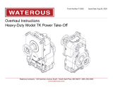
Figure 7. Installing the Chain
1. Wrap the chain (T18) around the drive (T5) and driven (T26) sprockets
making sure everything meshes and then lace the joining ends togeth‐
er using the connecting pin set (see Figure 7).
2. Insert the connecting pin rocker partway through the holes in the join‐
ing end links being careful of orientation (see Figure 9). The connect‐
ing rocker must be on the side of the guide link opposite the joining
end with the connecting rockers wide curved surface towards the
center of the hole.
3. Insert the connecting pin assembly along side the connecting rocker.
The two wide curved surfaces of the connecting pin and connecting
rocker must face each other.
4. After the connecting pin assembly and connecting rocker have been
pushed all the way through the joining ends of the chain, insert the spirol
pin into the open hole at the end of the connecting pin assembly (see
Figure 9). Make sure the spirol pin overlaps the connecting rocker.
5. Tighten cap screws connecting the driveshaft housing to the chain
case mid-section. Check chain for proper tension. Check deflection
half-way between the drive sprocket and driven sprocket (see chart
below for maximum deflection). Replace chain if deflection is greater
than those displayed in the chart below.
6. Loosen drive shaft housing cap screws for installation of lower case.
F-1031, Section 4307 Page 8 of 12
Cap and Driven Shaft Assembly
1. Make sure faces of flanges are clean and free of nicks and burrs.
2. If applicable, clean shims (T99) and / or spacer(s) (T100).
3. Install applicable dowel pins into mid-section (see appropriate SPL draw‐
ings). Apply a bead of silicone to mid-section flange inside of bolt holes. If
shims and spacers are required, install at this time. (For extended drop
cases built before 8/05/96, apply a bead of silicone between each spacer
inside of bolt pattern.)
4. Apply a bead of silicone to the top surface of the last shim (T99) and
spacer (T100).
5. Position previously assembled cap and driven shaft on dowels in the top
flange of the mid-section or spacer and tap down into contact with shims.
Install fasteners with lockwashers and tighten evenly.
NOTE: Fasteners used vary between models. Refer to the table in the
appropriate service parts lists for location and correct fasteners.
6. Invert mid-section and cap.
Installing the Chain
Drop
Max Deflection (In.)
(Both Directions)
B 1.75
C 1.75
D 1.75
E 2.0
F 2.0

F-1031, Section 4307 Page 9 of 12
Figure 8. Connecting Pin Set Figure 9. Connecting Pin Orientation
Spirol Pin
Connecting Rocker
Guide Link
Joining End of Chain
Connecting Pin Assembly
(Spirol pin on opposite
side must be tapped in to
complete installation.)
IL2433

F-1031, Section 4307 Page 10 of 12
Installing the Lower Section of Case to Mid-Section
1. Install lower shift shaft bushing (T112) into lower portion of case assembly
(T28).
2. Install dowels (T31) in flange of the mid-section portion of the case (T28).
3. Apply a bead of silicone inside the bolt pattern of the mid-section flange
(T28).
4. Position lower section of the case (T28) to the mid-section of the case,
align shift shaft and lower shift shaft bushing and set into place. Align with
dowels (T31) and tap into position until flanges of the mid-section and
lower section meet. Install cap screws (T93), bolts (T52), lockwashers
(T53) and nuts (T69) and tighten securely. See table in service parts list
for location of fasteners.
5. Install lower cap screws (T8 - before 5/06/04) or (T241 - after 5/06/04)
and lockwashers (T9) in drive shaft housing (T11) and tighten these fas‐
teners and previously installed fasteners.
Shift Collar Travel Adjustment
1. If shift collar adjustment is required, remove previously installed adjust‐
ment screw retainers (T87).
ROAD Adjustment
2. Put case into ROAD position. Measure the distance from the face of the
collar (T4) to the flange that the coupling shaft housing bolts to. Adjust
ROAD adjustment screw (T86) to set measurement at 3/4”.
PUMP Adjustment
3. Put the case into PUMP position. Measure the distance from the face of
the collar (T4) to the flange that the coupling shaft housing bolts to. Adjust
PUMP adjustment screw (T86) to set measurement at 2-1/16”.
4. Apply a dab of grease to slots in the shaft adjustment screws (T86) and
install adjustment screw retainers (T87). If equipped with a manual pump
shift, install shift cover gasket (T56) and shift cover (T55).
NOTE: Grease on adjustment screw (T86) will help keep the adjust‐
ment screw retainers in place until an appropriate cover or shift unit
is installed.
Installing the Coupling Shaft and Housing Assembly to the Case
NOTE: The drive line assembly was factory shimmed to limit the axial
float of the drive line. If any of the drive line parts have been changed, it
may be necessary to change the total thickness of shims (T41) between
the coupling shaft housing (T42) and the transmission case. Shims are
color coded for thickness as follows:
.005” = blue
.007” = natural
.010” = brown
The correct thickness of shims can be determined as follows:
1. Install previously assembled coupling shaft and housing assembly (T42)
with no shims between the housing and case. Tighten cap screws evenly
and tap the end of the coupling shaft with a soft mallet to force drive line
all the way forward.
NOTE: Do not overtighten cap screws. Doing so could cause inaccu‐
rate float measurement or damage to components.
2. Measure gap between housing and case in several places to assure a
uniform gap and add .005 - .010 in. This will be the total thickness of
shims needed to provide the recommended axial float of 0.005 in - 0.010
in.
3. Remove coupling shaft assembly from case after measuring gap.
NOTE: Field conditions may make it difficult to determine the correct
amount of shims. If in doubt, add another 0.005 in shims. No harm
will result from a small amount of additional axial float but bearing
life will be shortened if bearings are excessively preloaded.
4. Install correct amount of shims on the coupling shaft housing (T42) or if all
original parts are being reused, reinstall original shims (T41) (if not reus‐
able, replace with new shims). Install the coupling shaft assembly. If the
unit is equipped with a parking brake, make sure the coupling shaft hous‐
ing (T42) is properly orientated so that the drain tube (T85) will point down
when the case is reattached to the pump. Tighten housing to case (T74)
with cap screws (T8 - before 5/05/05) or (T241 - after 5/06/04).

F-1031, Section 4307 Page 11 of 12
Reassembly of Miscellaneous Parts
Tachometer Drive
1. Install tachometer driven gear (T89) in drive shaft housing (T11) making
sure it fits into bushing (T88) previously installed in the housing.
2. Install sleeve (T90) over end of gear (T89) and thread into housing (T11).
Miscellaneous Hardware
1. Install magnetic drain plug (T27).
2. Install breather (T134).
3. Install oil level plug (T73) and site plug (T134).
4. Install breather (T27) if removed.
5. Install sump oil strainer (T132).
6. If reusing flinger grommet (T137) and flinger disc (T138), install on impel‐
ler shaft.
NOTE: Tapered end of grommet should face the pump.
7. For cases built between 9/87 and 8/93, install V-style flinger (T138) with
flap towards the oil seal on the driven shaft. For cases built after 8/93 or
not re-using older flinger, install sealing boot.
Oil Pump
1. Install gasket (T96) over pilot diameter on oil pump (T34).
2. Position pump (T34) on adapter (T31).
3. Line up drive tang of oil pump shaft with slot in driven shaft.
4. Fit pilot diameter of oil pump (T34) into adapter (T31) making sure tang on
oil pump shaft and slot in driven shaft line up and engage. Fasten pump
(T34) to adapter (T31) with screws (T97) which pass through pump into
the adapter.
Oil Hoses
1. Install nipple (T101), tee (T102), hose (T64 or T67) if previously removed
and adapter union (T66) between discharge side of pump and spray tube
assembly.
2. Install street elbows (T57) at sump strainer (T132) and inlet of oil pump
(T34).
3. Install adapter union (T66) in elbow (T57) at sump strainer (T132).
4. Install hose (T67).
5. Install plug (T98) (a pressure gauge may have been installed) in tee (T102
and case (T28).
Reassembly of Accessories to the Transmission
Electric Shift Assembly
1. Make sure adjusting screws (T86) are in place and adjusted. Adjusting
screw retainer (T87) should be installed in slot end of each screw.
2. Position and bolt electric shift assembly into place making sure gasket
(T56) is installed between shift assembly and face of the case (T74).
Fasten in place with cap screws (T52).
3. Fasten pivot plate (T62) and cover (T75) to shift arm (T62) if these were
removed.
4. Reconnect wiring and check for proper adjustment of indicator light switch
if shift unit is so equipped.
NOTE: If chassis is equipped with an automatic transmission, indi‐
cator lights must be used.
Refer to separate operation and maintenance instructions for adjust‐
ment of the shift switch. For details of electric shift assembly, refer
to separate service parts list.
Pneumatic Shift Assembly
1. Make sure adjusting screws (T86) are in place and adjusted and adjusting
screw retainer (T87) installed in slot end of each screw.
2. Position and bolt pneumatic shift assembly into place making sure gasket
(T56) is installed between shift assembly and face of the case (T74).
Fasten in place with cap screws (T52).
3. Connect power supply and truck transmission interfaces.
4. SAE J1402 air brake hose recommended, 1/4” to 3/8”. Connect air lines
from main truck supply.
Brake Assembly
1. If previously removed, reinstall the drain tube (T85) in hole in bottom of
coupling shaft housing (T42).
2. Install and fasten brake assembly to coupling shaft housing (T42). Install
related linkage and brake drum, and adjust brake. For detailed instructions
on brake installation and adjustment, refer to separate instructions.

F-1031, Section 4307 Page 12 of 12
Priming Pump
1. Reinstall the priming pump and reconnect primer wiring, hose to priming
valve and tube to priming tank. As various types of priming pumps are
available, see separate instructions covering the type furnished with your
transmission.
Companion Flanges
1. Slide companion flange or end yoke on the drive shaft (T13) up against
the oil seal sleeve (T14) on pumps prior to 4/01/95. After 4/01/95, slide up
against the coupling shaft bearing (T15).
2. Install washer (T94) and lock nut (T43) (on 2” drivelines, no washers are
used); tighten nut securely. Cases built prior to 4/20/98: If reusing castel‐
lated lock nut (tighten as mush as possible), make sure one slot in the nut
lines up with hole in end of the drive shaft (T13). Install cotter pin (T12)
and spread open split end of pin. Cases built after 4/20/98: Anti-seize
should be applied to the threads before installing a self-locking nut. Do not
reuse self-locking nuts. Install self-locking nut and torque to 475 - 525
ft.-lbs.
NOTE: It is recommended that cases being rebuilt or repaired to
replace the castellated lock nut with a self-locking nut (T43) and
torque to 475 - 525 ft.-lbs.
3. Repeat same installation procedure at coupling shaft end unless compan‐
ion flange was previously installed at the time the brake assembly was
installed.
Propeller Shaft Reconnect
1. Reconnect drive line to companion flanges or end yoke. Tighten all connecting bolts securely.
Lubrication and Final Check
Fill transmission to oil level plug hole with automatic transmission fluid
(approximately 12-1/4 quarts required). The exact capacity will vary depend‐
ing on transmission ratio.
1. Recheck fasteners for tightness.
2. Check for oil leaks.
3. Recheck for proper operation of shift mechanism and that shift indicator
light system (if so equipped) is functioning properly.
Assembly of Case to Pump
CAUTION
Incorrect installation of the case to the pump could result in damage to chain
case and/or pump components.
1. Properly support the case and align splines on the case driven shaft and
pump impeller shaft.
2. Push case towards the pump.
3. Ensure pilot on the end of the impeller shaft aligns with the pilot hole in the
driven shaft. Also ensure the oil seal housing aligns with the bore in the
pump body.
4. Case and pump should be able to be assembled without the use of bolts
and nuts to draw them together.

/