Page is loading ...

CWI Series
Gas-Fired Natural Draft Water Boilers
INSTALLATION INSTRUCTIONS
These instructions must be afxed on or adjacent to the boiler
WARNING: Improper installation,
adjustment, alteration, service or
maintenance can cause property
damage, injury, or loss of life. For
assistance or additional informa-
tion, consult a qualied installer,
service agency or the gas
supplier. Read these instructions
carefully before installing.
Models:
• CWI103
• CWI138
• CWI172
• CWI207
• CWI241
• CWI276
• CWI311
• CWI346
• CWI380
Manufacturer of Hydronic Heating Products
P.O. Box 14818 3633 I. Street
Philadelphia, PA 19134
www.crownboiler.com
D ESIGNED TO L EAD
9902339


1
1
FOLLOW ALL INSTRUCTIONS and warnings
printed in this manual and posted on the boiler.
INSPECT THE BOILER ANNUALLY. To keep your
boiler safe and efficient, have a service technician
follow the Service checklist near the end of this
manual.
IF YOU ARE NOT QUALIFIED to install or service
boilers, do not install or service this one.
THE BOILER MAY LEAK WATER at the end of
its useful life. Be sure to protect walls, carpets,
and valuables from water that could leak from the
boiler.
PROTECT YOUR HOME IN FREEZING
WEATHER. A power outage, safety lockout, or
component failure will prevent your boiler from
lighting. In winter, your pipes may freeze and
cause extensive property damage. Do not leave
the heating system unattended during cold weather
unless alarms or other safeguards are in place to
prevent such damage
DO NOT BLOCK AIR FLOW into or around the
boiler. Insufficient air may cause the boiler to
produce carbon monoxide or start a fire.
KEEP FLAMMABLE LIQUIDS AWAY from the
boiler, including paint, solvents, and gasoline.
The boiler may ignite the vapors from the liquids
causing explosion or fire.
KEEP CHILDREN AND PETS away from hot
surfaces of the boiler, boiler piping, and vent pipe.
CARBON MONOXIDE (CO) is an odorless, deadly
gas that may be introduced into your home by
any malfunctioning fuel-burning product or vent
system failure. Consider installing CO alarms near
bedrooms in all levels of the building to warn you
and your family of potential CO exposure.
READ THIS ENTIRE MANUAL before attempting
installation, start-up, or service. Improper
installation, adjustment, alteration, service, or
maintenance may cause serious property damage,
personal injury, or death.
DO NOT DISCONNECT PIPE FITTINGS on the
boiler or in the heating system without first verifying
that the system is cool and free of pressure and
that your clothing will protect you from a release
of hot water or steam. Do not rely solely on the
boiler’s temperature and pressure gage when
making this judgment.
USE PROPER PERSONAL PROTECTION
EQUIPMENT when servicing or working near the
boiler. Materials of construction, flue products, and
fuel contain alumina, silica, heavy metals, carbon
monoxide, nitrogen oxides, and/or other toxic or
harmful substances that can are hazardous to
health and life and that are known to the State of
California to cause cancer, birth defects, and other
reproductive harm.
INSTALL ALL GUARDS, cover plates, and
enclosures before operating the boiler.
SIZE THE BOILER PROPERLY relative to the
design heat load or, if using domestic hot water
priority, the peak hot water load, whichever
is larger. A grossly oversized boiler will cycle
excessively and this will lead to premature failure
of the boiler and its components. Our warranty
does not apply to damage from excessive cycling.
ADHERE TO ALL LOCAL CODE
REQUIREMENTS. Contact your local code
inspector prior to installation. In the absence of
a local code, adhere to the National Fuel Gas
Code ANSI Z223.1/NFPA 54 or CAN/CSA B149.1,
Natural Gas and Propane Installation Code.
ALL WIRING must comply with the National
ElectrIcal Code ANSI/NFPA 70 (in the USA) or the
Canadian Electrical Code CSA C22.1 (in Canada)
and any local regulations.
WARNINGS FOR THE HOMEOWNER
WARNINGS FOR THE INSTALLER

2
2
Table of Contents
I. Product Description .................................................... 2
II. Specications ............................................................. 3
III. BeforeInstalling ......................................................... 4
IV. LocatingtheBoiler ..................................................... 4
V. AirforCombustion&Ventilation .............................. 5
VI. Venting ....................................................................... 9
VII.GasPiping..................................................................12
VIII.SystemPiping..........................................................13
IX.TanklessHeaterPiping..............................................18
X.Wiring........................................................................20
XI.Start-Up&Checkout.................................................24
XII.Service&Maintenance.............................................30
XIII.Troubleshooting........................................................33
XIV.Parts...........................................................................40
AppendixA:KnockdownBoilerAssembly.......................46
I Product Description
TheCWIseriesboilersarelowpressurecastirongasredhotwaterboilersdesignedforuseinclosedhotwaterheating
systems.TheseboilersareCategoryIdraftdiverterequippedappliances,whichmustbeventedbynaturaldraftusingalined
masonryorlistedmetalchimneysystem.Anadequatesupplyofairforcombustion,ventilationanddilutionofuegases
mustbeavailableintheboilerroom.
TheCWImaybeusedonforcedorgravityhotwaterheatingsystems.CWI103-CWI279includeatanklessheaterfor
domestichotwatergeneration.ThistanklessheaterisoptionalequipmentonCWI311-CWI380

3
3
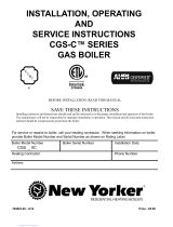
TABLE 1: CWI SPECIFICATIONS
II Specications
FIGURE1:CWIBOILERS-GENERALCONFIGURATION
INPUT
(MBH) (MBH) (Gal/min
)
4
"A" "B" "C" "D" (Gal)
CWI103 4 103 86 83.1 2.50 16 28 407/16 5 10.0
CWI138 5 138 115 83.1 3.00 191/4 28 407/16 6 12.2
CWI172 6 172 144 83.2 3.50 221/2 28 407/16 6 14.4
CWI207 7 207 173 83.2 3.75/4.50 253/4 30 407/16 7 16.6
CWI241 8 241 201 83.2
3.75/4.75
3
29 30 407/16 7 18.8
CWI276 9 276 230 83.2
4.00/5.25
3
321/4 30 407/16 8 21.0
CWI311 10 310 252
81.4
2
4.00/5.25
3
351/2 30 457/16 8 23.2
CWI346 11 345 281
81.4
2
4.00/5.25
3
383/4 30 457/16 9 25.4
CWI380 12 379 309
81.4
2
4.00/5.25
3
42 30 457/16 9 27.6
AHRINETRATINGSSHOWNAREBASEDONAPIPINGANDPICK-UPALLOWANCEOF1.15
2
THERMALEFFICIENCY
3
RATINGWITHOPTIONAL"HIGHCAPACITY"TANKLESSHEATER
200
4
TANKLESSHEATERRATINGSBASEDON40FINLETWATER,140FOUTLETWATERAND190FBOILERWATER.
RATINGSAREALSOBASEDON5MINUTEINTERMITTENTDRAWSWITH10MINUTESBETWEENDRAWS.
AHRINET
RATING
244
269
1
CWI311-CWI380NOTAVAILABLEFORUSEWITHLPGAS
BASIC
BOILER
MODEL
NUMBER
OF
SECTIONS (MBH)
NATURALORLPGAS
1
HEATING
CAPACITY DIMENSIONS(in.)
AFUE
(%)
WATER
VOL.
75
100
219
TANKLESS
HTR.RATING
125
150
175

4
4
III Before Installing
1) Safe,reliableoperationofthisboilerdependsuponinstallationbyaprofessionalheatingcontractorinstrictaccordance
withthismanualandtherequirementsoftheauthorityhavingjurisdiction.
• Intheabsenceofanauthorityhavingjurisdiction,installationmustbeinaccordancewiththismanualandthe
National Fuel Gas Code,ANSIZ223.1-latestedition.
• Whererequiredbytheauthorityhavingjurisdiction,thisinstallationmustconformtotheStandard for Controls and
Safety Devices for Automatically Fired Boilers(ANSI/ASMECSD-1)-latestedition.
2) Makesurethataproperlysizedchimneyisavailablewhichisingoodcondition.Consulttheauthorityhaving
jurisdiction,PartVIofthismanual,andtheNational Fuel Gas Codeforadditionalinformationonventingrequirements.
3) Makesurethattheboileriscorrectlysized.UseanindustryacceptedsizingmethodsuchastheI=B=R Installation
Guide for Residential Hydronic Heating Systems (Pub. #200) and I=B=R Heat Loss Calculation Guide(Pub.#H21or#H22)
publishedbytheHydronicsInstituteinBerkeleyHeightsNJ.
4) Makesurethattheboilerreceivedisconguredforthecorrectgas(naturalorLP).TheCWI311,CWI346andCWI380
mayonlybeusedwithnaturalgas.
5) Boilersinstalledataltitudesabove2000ft.mayrequiredifferentburnersandmainburneroricethanthoseatsealevel.
Makesurethattheboilerisconguredforuseatthecorrectaltitude.
6) Ifthisboilerwasreceivedasaknockdownboiler,followtheinstructionsinAppendixAtoassembletheboiler.
IV Locating the Boiler
1) Clearances:
• Observetheminimumclearancesshownbelow.Theseclearancesapplytoallcombustibleconstruction,aswellas
noncombustiblewalls,ceilingsanddoors.AlsoseeFigure2.
Front–18”
RightSide:
CWI311-CWI380withoutTanklessHeaters–18”
CWI103-CWI207withTanklessHeater-18”
CWI241-CWI380withStandardTanklessHeater-21”
CWI241-CWI380withHighCapacityTanklessHeater-24”
LeftSide–6”
Rear–6”
Top–17”
WARNING
FAILURE TO OBSERVE THE FOLLOWING LOCATION REQUIREMENTS COULD RESULT
IN A FIRE, EXPLOSION OR CARBON MONOXIDE (CO) HAZARD.
Warning
This Product Must be Installed By A Licensed Plumber Or Gas Fitter when Installed Within The
Commonwealth Of Massachusetts
If This Boiler is Equipped With a Tankless Heater, Tankless Heater Piping Must be Installed by a
Licensed Plumber When Boiler is Installed Within the Commonwealth of Massachusetts

5
5
• A24”serviceclearancefromthejacketisrecommendedontheleft,right,andfrontoftheboiler.Theseclearances
maybereducedtothoseshowninFigure2,howeverservicingtheboilerwillbecomeincreasinglydifcultasthese
serviceclearancesarereduced.
• Iftherightside24”serviceclearanceisreduced,adequateclearancemustbemaintainedtoeasilyreadandac-
cessthecontrols.Alternatively,accessmaybeprovidedusingadoor.Therightsideclearancesshownforboilers
equippedwithtanklessheatersallowforremovalofthetanklessheater.
2) Thisboilermaybeinstalleddirectlyoveranon-carpetedcombustibleoor.
3) Theboilermustbeinstalledonahardlevelsurface.
4) Donotinstallthisboilerinalocationwheregasolineorotherammablevaporsorliquidswillbestoredorused.Donot
installthisboilerinanareawherelargeamountsofairbornedustwillbepresent,suchasaworkshop.
5) Theboilershouldbelocatedasclosetothechimneyaspossible.
6) Donotinstallthisboilerdirectlyonasurfacethatmaygetwet.Raisetheboileronapad.
V Air for Combustion and Ventilation
WARNING
• INSUFFICIENT COMBUSTION AIR SUPPLY MAY RESULT IN THE PRODUCTION AND
RELEASE OF DEADLY CARBON MONOXIDE (CO) INTO THE HOME WHCH CAN CAUSE
SEVERE PERSONAL INJURY OR DEATH.
• THIS BOILER IS NOT DESIGNED FOR USE IN A SPACE THAT IS DEPRESSURIZED
RELATIVE TO THE OUTDOORS. OPERATING THIS BOILER IN A DEPRESSURIZED SPACE
MAY CAUSE SEVERE PERSONAL INJURY OR DEATH.
FIGURE2:CWIBOILERS-CLEARANCESTOALL
TYPESOFCOMBUSTIBLECONSTRUCTIONAND
NONCOMBUSTIBLECEILINGS,WALLS,AND
DOORS.
“X”
“X” (RH CLEARANCE)
ALL SIZES LESS TANKLESS HEATER - 18“
CWI103 - CWI241 WITH TANKLESS HTR. - 18“
CWI276 - CWI380 WITH TANKLESS HTR. - 21“
CWI207 - CWI380 WITH HIGH CAPY. TANKLESS HTR. - 24“

6
6
Sufcientfreshairmustbesuppliedforcombustion,ventilationanduegasdilution.Provisionsforcombustion,ventilation
anduegasdilutionairforgasutilizationequipmentventedbynaturaldraftmustbemadeinaccordancewithlocalbuilding
codesor,inabsenceofsuchcodes,inaccordancewithsections5.3.3and5.3.4(“AirforCombustionandVentilation”)ofthe
National Fuel Gas Code,NFPA54/ANSIZ223.1.
Toensureanadequatesupplyofcombustion,ventilationanduegasdilutionairsupply,startbydeterminingwhether
theboileristobeinstalledinabuildingofunusuallytightconstruction.Agooddenitionofabuildingofunusuallytight
constructionisonewhichhasallofthefollowingfeatures:
• Wallsandceilingsexposedtooutsideatmospherehaveacontinuouswatervaporretarderwitharatingof1permor
lesswithopeningsgasketedandsealed
• Weatherstrippinghasbeenaddedonopenablewindowsanddoors
• Caulkingandsealantsareappliedtoareassuchasjointsaroundwindowanddoorframes,betweensoleplatesand
oors,betweenwall-ceilingjoints,betweenwallpanels,atpenetrationsforplumbing,electrical,andgaslines,and
atotheropenings.
For Buildings of Other than Unusually Tight Construction
1) Determinewhethertheboileristobeinstalledinaconnedspace-AconnedspaceisdenedbytheNational Fuel
Gas Codeashavingavolumelessthan50cubicfeetper1000BTU/hrinputofallappliancesinstalledinthatspace.To
determinewhethertheboilerroomisaconnedspace:
a. TotaltheinputofallappliancesintheboilerroominthousandsofBTU/hr.Roundtheresulttothenexthighest1000
BTU/hr.
b. Findthevolumeoftheroomincubicfeet.Thevolumeoftheroomincubicfeetis:
Length(ft)xwidth(ft)xceilingheight(ft)
Incalculatingthevolumeoftheboilerroom,considerthevolumeofadjoiningspacesonlyifnodoorsareinstalled
betweenthem.Ifdoorsareinstalledbetweentheboilerroomandanadjoiningspace,donotconsiderthevolumeofthe
adjoiningspace,evenifthedoorisnormallyleftopen.
c. DividethevolumeoftheboilerroombytheinputinthousandsofBTU/hr.Iftheresultislessthan50,theboilerroomis
aconnedspace.
Example:
ACWI172ENandawaterheateraretobeinstalledinaroommeasuring6ft-3inx7ftwithan8ftceiling.Thewater
heaterhasaninputof30000BTU/hr:
TotalinputinthousandsofBTU/hr=(172000BTU/hr+30000BTU/hr)/1000=202
Volumeofroom=6.25ftx7ftx8ft=350ft
3
350/202=1.73.Since1.73islessthan50,theboilerroomisaconnedspace.
2) UnconnedSpace-Naturalinltrationintotheboilerroomwillnormallyprovideadequateairforcombustionand
ventilationwithoutadditionallouversoropeningsintoboilerroom.
3) ConnedSpace-Providetwoopeningsintotheboilerroom,oneneartheoorandoneneartheceiling.Thetopedgeof
theupperopeningmustbewithin12”oftheceilingandthebottomedgeoftheloweropeningmustbewithin12”ofthe
oor(Figure3).
• Eachopeningmusthaveafreeareaof1squareinchper1000BTU/hrinputofallgasburningappliancesintheboiler
room.Theminimumopeningdimensionis3inches.Minimumopeningfreeareais100squareinchesperopening.
• Ifthetotalvolumeofboththeboilerroomandtheroomtowhichtheopeningsconnectislessthan50cubicfeetper
1000BTU/hroftotalapplianceinput,installapairofidenticalopeningsintoathirdroom.Connectadditionalrooms
withopeningsuntilthetotalvolumeofallroomsisatleast50cubicfeetper1000BTU/hrofinput.
• The“freearea”ofanopeningtakesintoaccounttheblockingeffectofmesh,grills,andlouvers.Wherescreensare
used,theymustbenonerthan¼”(4x4)mesh.
• Ifprovidingopeningsintoadjacentroomsisundesirable,combustionandventilationaircanbebroughtintotheboiler
roomfromoutdoors.Seetheinstructionsunder“ForBuildingsofUnusuallyTightConstruction”.

7
7
FIGURE4:ALLAIRFROMOUTDOORS,
VENTILATEDCRAWLSPACEANDATTIC
FIGURE5:ALLAIRFROMOUTDOORS,
VIA VENTILATED ATTIC
FIGURE3:BOILERINSTALLEDINCONFINEDSPACE,
ALLAIRFROMINSIDE

8
8
FIGURE6:ALLAIRFROMOUTDOORS,USING
OPENINGSINTOBOILERROOM
FIGURE7:ALLAIRFROMOUTDOORS,USING
HORIZONTALDUCTSINTOBOILERROOM

9
9
For Buildings of Unusually Tight Construction
1) Openingsmustbeinstalledbetweentheboilerroomandtheoutdoorsoraventilatedspace,suchasanatticorcrawl
space,whichcommunicatesdirectlywiththeoutdoors.
2) Twoopeningsarerequired.Thetopedgeoftheupperopeningmustbewithin12inchesoftheceiling.Thebottomedge
oftheloweropeningmustbewithin12inchesoftheoor.
3) Sizeopeningsandductsasfollows:
• Verticalductsoropeningsdirectlyoutdoors(Figure4,Figure5,andFigure6)-Eachopeningmusthaveafreecross
sectionalareaof1squareinchper4000BTU/hrofthetotalinputofallgas-redappliancesintheboilerroombutnot
lessthan100squareinches.Minimumopeningsizeis3inches.
• Openingstooutdoorsviahorizontalducts(Figure7)-Eachopeningmusthaveafreecrosssectionalareaof1square
inchper2000BTU/hrofthetotalinputofallgasredappliancesintheboilerroombutnotlessthan100squareinches.
Minimumopeningsizeis3inches.
• The“freearea”ofanopeningtakesintoaccounttheblockingeffectofmesh,grills,andlouvers.Wherescreensare
used,theymustbenonerthan¼”(4x4)mesh.
VI Venting
Ventinstallationmustbeinaccordancewithlocalbuildingcodes,orthelocalauthorityhavingjurisdiction,ortheNational
Fuel Gas Code,NFPA54/ANSIZ223.1.
AtypicalventinstallationisillustratedbyFigure8.Thecomponentsofventinstallationaretheventdamper,ventconnector
andchimney.
1) AcceptableChimneys-ThefollowingchimneysmaybeusedtoventCWIseriesboilers:
• ListedTypeBorLgasvent-Installinaccordancewiththemanufacturer’sinstructions,thetermsofitslisting,and
applicablecodes.
• MasonryChimney-ThemasonrychimneymustbeconstructedinaccordancewiththeStandard for Chimneys,
Fireplaces, Vents, and Solid Fuel Burning Appliances(NFPA211)andlinedwithaclaylinerorotherlistedlining
system.DonotventaCWIseriesboilerintoanunlinedchimney.
2) AcceptableVentConnectors-Thefollowingmaybeusedforventconnectors:
• ListedtypeBorLGasVent
• SingleWallGalvanizedPipe-Use0.018”(26gaugeorheavier).Thesizeandlocationofthechimneymaynot
permittheuseofasinglewallconnectorinsomecases.SeetheNational Fuel Gas Code.Donotusesinglewall
pipeforventconnectorsinattics.
• OtherVentConnectorsPermittedbytheNational Fuel Gas Code.
3) ChimneyandVentConnectorSizing-SizethechimneyandventconnectorinaccordancewiththeNational Fuel Gas
Code.
4) ExteriorChimneys-Anexteriorchimneyhasoneormoresidesexposedtotheoutdoorsbelowtheroofline.Thereare
twoconditionsunderwhichanexteriorchimneymaybeused:
WARNING
• IMPROPER VENTING MAY RESULT IN PROPERTY DAMAGE AND/OR THE RELEASE OF
FLUE GASES, WHICH CONTAIN DEADLY CARBON MONOXIDE (CO), INTO THE HOME,
WHICH CAN CAUSE SEVERE PERSONAL INJURY OR DEATH.
• DO NOT USE PLASTIC VENTING MATERIALS (SUCH AS CPVC, PVC AND RADEL) TO VENT
THIS BOILER.
• INSPECT EXISTING CHIMNEY BEFORE INSTALLING BOILER. FAILURE TO CLEAN OR
REPLACE DAMAGED PIPE OR TILE LINING WILL CAUSE SEVERE INJURY OR DEATH.

10
10
• In some very restrictivecases,CWIseriesboilersmaybeventedintoanexteriorceramiclinedmasonrychimney.
SeetheNational Fuel Gas Codeforinformationonwhenexteriorchimneysmaybeused.
• AnexteriormasonrychimneymaybeusedifitislinedwithBventoralistedchimneyliningsystem.
5) Thisboilermaybeventedusingalistedpowerventer.Thepowerventermustbeinsizedandinstalledinaccordance
withthepowerventermanufacturer’sinstructions,thetermsofthepowerventerlisting,andapplicablecodes.Theboiler
mustbeelectricallyinterlockedwiththepowerventertopreventboileroperationifthepowerventerfailstooperate.Before
decidingtouseapowerventer,makecertainthattheuegasexitingthepowerventerwillnotdamageadjacentconstruction
orotherstructures.Alsomakecertainthatthepowerventerterminalwillnotbesubjectedtowindswhichcouldeffectpower
venteroperation.
6) Donotconnecttheventofthisapplianceintoanyportionofamechanicalventsystemoperatingunderpositivepressure.
7) Donotconnecttheboilerintoachimneyueservinganopenreplaceorothersolidfuelappliance.
8) Priortoboilerinstallation,inspectchimneyforobstructionsorotherdefectsandcorrectasrequired.Cleanchimneyas
necessary.
9)Ventpipeshouldslopeupwardfromdraftdiverternotlessthanoneinchinfourfeet.Noportionofventpipeshouldrun
downwardorhavesags.Ventpipemustbesecurelysupported.
10) Theverticalsectionofventpipecomingofftheboilershouldbeastallaspossible,whilestillmaintainingtheproper
clearancefromthehorizontalventconnectortocombustiblesandtheproperpitchcalledforin(9)above.
11) Ventpipeshouldbeinstalledabovethebottomofthechimneytopreventblockage.
12) Ventpipemustbeinsertedushwithinsidefaceofthechimneylinerandthespacebetweenventpipeandchimney
sealedtight.
13) Donotinstalltheventdamperinanyportionoftheventsystemwhichisusedbyappliancesotherthantheboilerbeing
installed.
14) VentdamperinstallationismandatoryonallCWIboilermodelsexcepttheCWI311-CWI380.Installventdamper(see
Figure9)asfollows:
a) Openventdampercartonandremoveinstallationinstructions.Readtheinstructionsthoroughlybeforeproceeding.
Verifythatventdamperissamesizeasdraftdiverteroutlet.SeeFigure1.Unpackventdampercarefully.Do not
force closed damper blade. Forcingventdamperclosedmayresultindamagedgeartrainandvoidwarranty.
b) Ventdamperisfactoryshippedhavingapproximately¾”diameterholeintheventdamperblade,whichmust be
left openforboilersequippedwithstandingpilot,andshouldbepluggedonboilerswithanintermittentpilot,using
theplugsuppliedwiththedamper.
Mounttheventdamperontheuecollarwithoutmodicationtoeitherandsecurewithsheetmetalscrews.Make
surescrewsdonotinterferewithdamperbladeoperation.Ventdamperbladepositionindicatormustbevisibleto
users.
c) Thedamperwireharnessisshippedwiredintotheboilerjunctionbox.Plugthelooseendofthisharnessintothe
damperandsecuretheexibleconduittothedamperusingaconnectornutprovided.
d) Installventconnectorpipeandventttingsfromventdamperoutlettochimneyorgasvent.Securewithsheetmetal
screwsandsupportasrequired.
Removing an Existing Boiler from a Common Chimney
Insomecases,whenanexistingboilerisremovedfromacommonchimney,thecommonventingsystemmaybetoolarge
fortheremainingappliances.Atthetimeofremovalofanexistingboilerthefollowingstepsshallbefollowedwitheach
applianceremainingconnectedtothecommonventingsystemplacedinoperation,whiletheotherappliancesremaining
connectedtothecommonventingsystemarenotinoperation.
a) Sealanyunusedopeninginthecommonventingsystem.
b) Visuallyinspecttheventingsystemforpropersizeandhorizontalpitchanddeterminethereisnoblockageor
restriction,leakage,corrosionandotherdeciencieswhichcouldcauseanunsafecondition.
c) Insofaraspractical,closeallbuildingdoorsandwindowsandalldoorsbetweenthespaceinwhichalltheappliances
remainingconnectedtothecommonventingsystemarelocatedandotherspacesofthebuilding.Turnonclothes
dryersandanyappliancenotconnectedtothecommonventingsystem.Turnonanyexhaustfans,suchasrange
hoodsandbathroomexhausts,sotheywilloperateatmaximumspeed.Donotoperateasummerexhaustfan.Close
replacedampers.

11
11
FIGURE8:CWIBOILERTYPICALVENTSYSTEM
INSTALLATION AND COMPONENTS
FIGURE9:VENTDAMPERINSTALLATIONDETAILS

12
12
d) Placeinoperationtheappliancebeinginspected.Followthelightinginstructions.Adjustthermostatsotheappliance
willoperatecontinuously.
e) Testforspillageatthedrafthoodreliefopeningafterve(5)minutesofmainburneroperation.Usetheameofa
matchorcandle,orsmokefromacigarette,cigar,orpipe.
f) Afterithasbeendeterminedthateachapplianceremainingconnectedtothecommonventingsystemproperlyvents
whentestedasoutlinedabove,returndoors,windows,exhaustfans,replacedampersandanyothergas-burning
appliancestotheirpreviousconditionofuse.
g) Anyimproperoperationofthecommonventingsystemshouldbecorrectedsotheinstallationconformswiththe
NationalFuelGasCode,ANSIZ223.1.Whenresizinganyportionofthecommonventingsystem,thecommon
ventingsystemshouldberesizedtoapproachtheminimumsizeasdeterminedusingtheappropriatetablesinthe
NationalFuelGasCode,ANSIZ223.1.
VII Gas Piping
Gaspipingtotheboilermustbesizedtodeliveradequategasfortheboilertoreatthenameplateinputataline
pressurebetweentheminimumandmaximumvaluesshownontheratingplate.Formoreinformationongaslinesizing,
consulttheutilityorChapter2oftheNational Fuel Gas Code.
Figure10showstypicalgaspipingconnectiontotheCWIboiler.Asedimenttrapmustbeinstalledupstreamofallgas
controls.Installamanualshut-offvalveoutsidethejacketandgroundjointunionasshown.
FIGURE10:GASCONNECTIONTOBOILER
*StateofMassachusettsRequiresManual
Shut-offValvetobe“T”HandleType
*
WARNING
• SHUT OFF GAS SUPPLY BEFORE SERVICING THE BOILER.
• ALL GAS PIPING MUST BE GAS TIGHT. USE GAS RATED THREAD COMPOUND
ON ALL THREADED JOINTS TO AVOID LEAKS, WHICH MAY RESULT IN FIRE OR
EXPLOSION.
• SIZE GAS PIPING, REGULATORS, VALVES AND METERS SO AS TO PROVIDE AN
ADEQUATE GAS FLOW AND PRESSURE TO THE BOILER DURING OPERATION.
FAILURE TO DO SO MAY CAUSE POOR COMBUSTION, NOISE, INJURY OR
DEATH.

13
13
VIII System Piping
Standard Piping
Figure11showstypicalboilersystemconnectionsonasinglezonesystem.Additionalinformationonhydronicsystem
designmaybefoundinInstallation of Residential Hydronic Systems(Pub.#200)publishedbytheHydronicsInstitutein
BerkeleyHeights,NJ.Thecomponentsinthissystemandtheirpurposesareasfollows:
1) Reliefvalve(Required)-MountthereliefvalveontherightsideoftheboilerasshowninFigure1usingthe3/4nipples
andelbowprovided.Thereliefvalveshippedwiththeboilerissettoopenat30psi.Thisvalvemaybereplacedwithone
havingapressureuptothe“MAWP,WATER”shownontheratingplate.Ifthevalveisreplaced,thereplacementmust
haveareliefcapacityinexcessoftheDOEheatingcapacityfortheboiler.
Pipethedischargeofthereliefvalvetoalocationwherewaterorsteamwillnotcreateahazardorcausepropertydamage
ifthevalveopens.Theendofthedischargepipemustterminateinanunthreadedpipe.Ifthereliefvalvedischargeis
notpipedtoadrainitmustterminateatleast6inchesabovetheoor.Donotrunreliefvalvedischargepipingthroughan
areathatispronetofreezing.Theterminationofthereliefvalvedischargepipingmustbeinanareawhereitisnotlikely
tobecomepluggedbydebris.
2) Circulator(Required)-Althoughthecirculatorisshippedontheboilerreturn,itcanbeinstalledontheboilersupply.If
thecirculatorismovedtothesupply,itshouldbepositionedjustdownstreamoftheexpansiontankasshowninFigure
11.
3) ExpansionTank(Required)-Ifthisboilerisreplacinganexistingboilerwithnootherchangesinthesystem,the
oldexpansiontankcangenerallybereused.Iftheexpansiontankmustbereplaced,consulttheexpansiontank
manufacturer’sliteratureforpropersizing.
Theboileranditsgasconnectionmustbeleaktestedbeforeplacingtheboilerinoperation.Whendoingthis,theboilerand
itsindividualshut-offmustbedisconnectedfromtherestofthesystemduringanypressuretestingofthatsystematpressures
inexcessof1/2psi.Whenpressuretestingthegassystematpressuresof1/2psiorless,isolatetheboilerfromthegassupply
systembyclosingitsindividualmanualshut-offvalve.
WARNING
• INSTALL BOILER SO THAT THE GAS IGNITION SYSTEM COMPONENTS ARE
PROTECTED FROM WATER (DRIPPING, SPRAYING, RAIN, ETC.) DURING
APPLIANCE OPERATION AND SERVICE (CIRCULATOR REPLACEMENT, ETC.).
• OPERATION OF THIS BOILER WITH CONTINUOUS RETURN TEMPERATURES
BELOW 120°F CAN CAUSE SEVERE HEAT EXCHANGER CORROSION DAMAGE.
• OPERATION OF THIS BOILER IN A SYSTEM HAVING SIGNIFICANT AMOUNTS OF
DISSOLVED OXYGEN CAN CAUSE SEVERE HEAT EXCHANGER CORROSION
DAMAGE.
• DO NOT USE TOXIC ADDITIVES, SUCH AS AUTOMOTIVE ANTIFREEZE, IN A
HYDRONIC SYSTEM.
• PIPE RELIEF VALVE DISCHARGE TO A SAFE LOCATION. THE RELIEF VALVE
MAY DISCHARGE SCALDING HOT WATER.
• DO NOT INSTALL A VALVE IN THE RELIEF VALVE DISCHARGE LINE.
• DO NOT MOVE RELIEF VALVE FROM FACTORY LOCATION.
• DO NOT PLUG RELIEF VALVE DISCHARGE. BLOCKING THE RELIEF VALVE MAY
RESULT IN BOILER EXPLOSION.

14
14
4) FillValve(Required)-Eitheramanualorautomaticllvalvemaybeused.Theideallocationforthellisatthe
expansiontank.
5) AutomaticAirVent(Required)-Atleastoneautomaticairventisrequired.Manualventswillusuallyberequiredin
otherpartsofthesystemtoremoveairduringinitialll.
6) LowWaterCut-Off(Requiredinsomesituations)-Alowwatercutoffisrequiredwhentheboilerisinstalledabove
radiation.Inaddition,somecodessuchasASMECSD-1requirelowwatercutoffs.Codesmayalsorequirethatthislow
watercutoffhaveamanualresetfunction.Thelowwatercutoffmaybeaoattypeorprobetype,butmustbedesigned
foruseinahot-watersystem.Thelowwatercutoffshouldbepipedintotheboilersupplyjustabovetheboilerwithno
interveningvalvesbetweenitandtheboiler.
Usealowwatercutoffthatbreaksthe120VACsupplytotheboiler.Donotattempttowirea24-voltlowwatercutoff
intotheboilerfactorywiring.
7) ManualResetHighLimit(Requiredbysomecodes)-ThiscontrolisrequiredbyASMECSD-1andsomeothercodes.
Installthehighlimitintheboilersupplypipingjustbeyondtheboilerwithnointerveningvalves.Setthemanualreset
highlimitasfarabovetheoperatinglimitsettingaspossible,butnotover240°F.Wirethecontroltobreakthe120VAC
electricalsupplytotheboiler.
8) FlowControlValve(Requiredundersomeconditions)-Theowcontrolvalvepreventsowthroughthesystemunless
thecirculatorisoperating.Aowcontrolvalvemaybenecessaryonconvertedgravitysystemstopreventgravity
circulation.Flowcontrolvalvesarealsousedtoprevent“ghostows”incirculatorzonesystemsthroughzonesthatare
notcallingforheat.
9) IsolationValves(Optional)-Isolationvalvesareusefuliftheboilermustbedrained,astheywilleliminatehavingtodrain
andrelltheentiresystem.
10) DrainValve-Thedrainvalveisshippedintheboilerpartsbag.Installitintheteeunderthecirculatorasshownin
Figure1.
Piping for Special Situations
Certaintypesofheatingsystemshaveadditionalrequirements.Someofthemorecommonvariationsfollow:
1) IndirectWaterHeaters-Figure12showstypicalindirectwaterheaterpiping.Boilerpipingisthesameasforanytwo-
zonesystem.Figure12showscirculatorzoning,whichisusuallypreferredforindirectwaterheaters.Sizethecirculator
andindirectwaterheaterpipingtoobtaintheboilerwaterowthroughtheindirectwaterheatercalledforbytheindirect
waterheatermanufacturer.
2) LargeWaterVolumeSystems-ThepipingshowninFigure13willminimizetheamountoftimethattheboileroperates
withreturntemperaturesbelow120°Fonthesesystems.Abypassisinstalledasshowntodivertsomesupplywater
directlyintothereturnwater.Thebypasspipeshouldbethesamesizeasthesupply.Thetwothrottlingvalvesshownare
adjustedsothatthereturntemperaturerisesabove120°Fduringtherstfewminutesofoperation.Athree-wayvalvecan
besubstitutedforthetwothrottlingvalvesshown.Ifthecirculatorismountedonthesupply,thebypassmustbeonthe
dischargesideofthecirculator.
3) LowTemperatureSystems-Somesystems,suchasradianttubingsystems,requirethesystemwatertemperatureto
belimitedtoavaluebelowthetemperatureofthewaterleavingtheCWI.Thesesystemsalsotypicallyhavereturn
temperatureswellbelowthe120°Fminimum.
Figure14illustratestheuseofaheatexchangertoconnecttheCWIboilertothistypeofsystem.Theheatexchanger
willpermitthetransferofheatfromtheboilerwatertothelowtemperaturesystemwhileholdingthesystemsupplyand
boilerreturntemperatureswithintheirlimits.Forthissystemtoworkproperlytheheatexchangermustbeproperlysized
andthecorrectowratesarerequiredoneithersideoftheheatexchanger.Consulttheheatexchangermanufacturerfor
sizinginformation.Thewaterintheboileriscompletelyisolatedfromthewaterinthesystem.Thismeansthatseparate
llandexpansiontanksarerequiredfortheheatingsystemloop.
Thereareseveralotherwaystoconnectlowtemperaturesystemstonon-condensingboilersliketheCWI,suchasfour
waymixingvalveandvariablespeedinjectionpumpingsystems.
4) Systemscontainingoxygen-Manyhydronicsystemscontainenoughdissolvedoxygentocauseseverecorrosiondamage
toacastironboilersuchastheCWI.Someexamplesinclude:
• Radiantsystemsthatemploytubingwithoutanoxygenbarrier.
• Systemswithroutineadditionsoffreshwater.
• Systemswhichareopentotheatmosphere.

15
15
FIGURE12:INDIRECTWATERHEATER
BOILERSIDEPIPING
FIGURE11:STANDARDBOILERPIPING

16
16
Iftheboileristobeusedinsuchasystem,itmustbeseparatedfromtheoxygenatedwaterbeingheatedwithaheat
exchangerasshowninFigure14.
Consulttheheatexchangermanufacturerforproperheatexchangersizingaswellasowandtemperaturerequirements.
Allcomponentsontheoxygenatedsideoftheheatexchanger,suchasthepumpandexpansiontank,mustbedesignedfor
useinoxygenatedwater.
5) PipingwithaChiller-Iftheboilerisusedinconjunctionwithachiller,pipetheboilerandchillerinparallelasshownin
Figure15.Useisolationvalvestopreventchilledwaterfromenteringtheboiler.
6) AirHandlers-Wheretheboilerisconnectedtoairhandlersthroughwhichrefrigeratedairpasses,useowcontrolvalves
intheboilerpipingorotherautomaticmeanstopreventgravitycirculationduringthecoolingcycle.
7)GravityHotWaterSystems-TheCWIissuitableforinstallationinagravityhotwatersystem.Figure16showspiping
foragravityhotwaterboiler.Thecirculator,1-1/2”x2”bushings,and1-1/2”pipingareremovedandthesystempipingis
rundirectlytothe2”supplyandreturntappingsontheboiler.Ifisolationvalvesareinstalled,theyshouldbegatevalves
or“fullport”ballvalves.
Ifitisdesiredtoconvertthegravitysystemtoforcedhotwater,thefactorysuppliedcirculatorandpipingareusedasis.
Agravityhotwatersystemisa“largewatervolumesystem”(see(2)above)andshouldbepipedwithabypassasshown
inFigure13.Manygravityhotwatersystemshavebalancingoriceinstalledintheradiators.Theseoricemayneedto
beremovedtoobtainproperheatdistributionwhenthesystemisconvertedtoforcedhotwater.
FIGURE13:BOILERBYPASSPIPING

17
17
FIGURE15:BOILERPIPINGWITHCHILLER
FIGURE14:ISOLATIONOFBOILERFROMSYSTEMWITHAHEATEXCHANGER

18
18
IX TANKLESS HEATER PIPING
IftheCWIissuppliedwithatanklessheater,pipetheheaterasshowninFigure17.Thecomponentsinthissystemand
theirfunctionsareasfollows:
1)MixingValve(Required)-Duringtheheatingseason,thewaterexitingthetanklessheatermaybe180degreesormore.
Themixingvalveblendshotwaterleavingthetanklessheaterwithcoldwatersoastomaintainthehotwatersupplied
tothexturesataxedtemperature.Thissavesenergy,increasestheamountofusablehotwateravailabletothe
homeowner,andreducestheriskofscalding.
Installamixingvalvewithasettingrangeofapproximately110to130F.Followthemanufacturer’sinstructionsfor
installingthisvalve.Usuallya“heattrap”willberequiredbetweenthecoilandthe“hot”connectiononthemixingvalve.
FIGURE16:GRAVITYPIPING
WARNING
A MIXING VALVE DOES NOT ELIMINATE THE RISK OF SCALDING.
• SET THE MIXING VALVE AND BOILER LOW LIMIT ADJUSTMENTS AS LOW
AS POSSIBLE.
• FEEL WATER BEFORE SHOWERING OR BATHING.
• IF ANTI-SCALD OR ANTI-CHILL PROTECTION IS REQUIRED, USE DEVICES
SPECIFICALLY DESIGNED FOR SUCH SERVICE. INSTALL AND MAINTAIN
THESE DEVICES IN ACCORDANCE WITH THE MANUFACTURER’S
INSTRUCTIONS. DO NOT USE THE MIXING VALVE AS A SUBSTITUTE
FOR PRESSURE BALANCING VALVES OR OTHER DEVICES REQUIRED BY
PLUMBING CODES TO PROTECT AGAINST SCALDING.
/