Page is loading ...

1
D E S I G N E D T O L E A D
Tel: (215) 535-8900 • Fax: (215) 535-9736 • www.crownboiler.com
Manufacturer of Hydronic Heating Products
P.O. Box 14818 3633 I. Street
Philadelphia, PA 19134
Series 16
Gas-Fired Natural Draft Water Boilers
INSTALLATION AND OPERATING INSTRUCTIONS
These instructions must be affixed on or adjacent to the boiler.
WARNING: Improper installation,
adjustment, alteration, service or
maintenance can cause property
damage, injury, or loss of life. For
assistance or additional information,
consult a qualified installer, service
agency or the gas supplier. Read
these instructions carefully before
installing.

2

3
Table of Contents
I. Product Description . . . . . . . . . . . . . . . . . . . 1
II. Specifications . . . . . . . . . . . . . . . . . . . . . . . . 2
III. Before Installing . . . . . . . . . . . . . . . . . . . . . . 3
IV. Locating the Boiler . . . . . . . . . . . . . . . . . . . . 3
V. Knockdown Boiler Assembly Instructions 6
A. Prior To Assembly . . . . . . . . . . . . . . . 6
B. Boiler Assembly, Installation
& Leak Testing . . . . . . . . . . . . . . . . . . 6
C. Jacket Assembly . . . . . . . . . . . . . . . . . 8
D. Ignition Control & Gas Valve Installation
Standard Control System . . . . . . . 9
CSD-1 Control System . . . . . . . . . 9
E. Control & Trim Installation . . . . . . . 12
VI. Air for Combustion & Ventilation . . . . . . . .13
VII. Venting . . . . . . . . . . . . . . . . . . . . . . . . . . . . . 17
VIII. System Piping . . . . . . . . . . . . . . . . . . . . . . . . 21
A. Heating System Piping . . . . . . . . . . . 21
B. Piping for Special Situations . . . . . . 22
IX. Gas Piping . . . . . . . . . . . . . . . . . . . . . . . . . . 25
X. Control System Wiring . . . . . . . . . . . . . . . . 26
A. Standard . . . . . . . . . . . . . . . . . . . . . . 27
B. CSD-1 . . . . . . . . . . . . . . . . . . . . . . . . 27
XI. Start-Up & Checkout . . . . . . . . . . . . . . . . . . 31
XII. Service & Maintenance . . . . . . . . . . . . . . . . 35
XIII. Parts . . . . . . . . . . . . . . . . . . . . . . . . . . . . . . . 37
I Product Description
The Series 16 boiler is a cast iron hot water boiler designed for use in closed forced circulation hot water heating systems
found in large homes, multifamily dwellings, small businesses, office complexes and other commercial heating applications.
These boilers are Category I draft hood equipped appliances, which must be vented by natural draft using a lined masonry or
listed metal chimney system. An adequate supply of air for combustion, ventilation and dilution of flue gases must be
available in the boiler room. This boiler is intended for use with natural gas or LP / Propane gas.
1

4
2
II Specifications

5
III Before Installing
1) Safe, reliable operation of this boiler depends upon installation by a professional heating contractor in strict
accordance with this manual and the requirements of the authority having jurisdiction.
• In the absence of an authority having jurisdiction, installation must be in accordance with this manual and the latest
edition of the National Fuel Gas Code, ANSI Z223.13.
• Where required by the authority having jurisdiction, this installation must conform to the latest edition of the
Standard for Controls and Safety Devices for Automatically Fired Boilers (ANSI/ASME CSD-1).
2) Make sure that a properly sized chimney is available and is in good condition. Consult the authority having
jurisdiction, Part VII of this manual and the National Fuel Gas Code for additional information on venting
requirements.
Series 16 boilers are equipped with an external draft hood which must be installed without alteration. Make sure
adequate head room exists to install Series 16 boiler models with the unaltered draft hood while maintaining proper
clearances from the vent connector to combustible materials.
3) Make sure that the boiler is correctly sized by utilizing an industry accepted sizing method.
4) Make sure that the boiler to be installed is configured for the correct gas (natural or LP).
5) Boilers installed at altitudes above 2000 ft. require different main burner orifice than those at sea level. Make sure that
the boiler is configured for use at the correct altitude.
6) Follow the instructions in Section V to assemble the boiler.
IV Locating the Boiler
1) Do not install this boiler directly on a combustible floor. This boiler may be installed over a non-carpeted combustible
floor by using the following special bases available from Crown.
Boiler Model Combustible Flooring Base #
16-325 500506
16-390 500507
16-455 500508
16-520 500509
16-585 500510
2) Series 16 clearance and other boiler room space requirements depend upon the size of the boiler:
Models 16-325, 16-390 – These sizes are approved for alcove installation. Install with the minimum clearances shown
in Table 2. The clearances shown in Table 2 apply to all combustible construction as well as non-combustible walls,
floors, ceilings and doors (also see Figure 2).
Models 16-455, 16-520, 16-585 – These sizes must be installed in a boiler room that is “large in comparison to the
boiler”. Such a room is defined as having a volume at least 16 times that of the boiler. Table 3 shows the required
minimum boiler room volumes required for these three sizes. To find the volume of the boiler room calculate:
Boiler Room Volume (ft
3
) = Length (ft) x Width (ft) x Height (ft)
If the boiler room height is greater than 8ft, use 8ft in the above equation.
In addition to the minimum boiler room volume requirement, these three sizes must be installed with the minimum
clearances shown in Table 2. The clearances shown in Table 2 apply to all combustible construction as well as non-
combustible walls, floors, ceilings and doors (also see Figure 2).
3
WARNING
This Product Must Be Installed By A Licensed Plumber Or Gas Fitter When Installed Within The
Commonwealth Of Massachusetts.

6
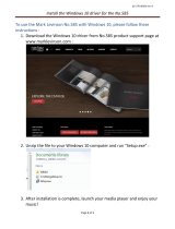
Figure 2: Minimum Clearances to Combustibles
4
All Models - The following service clearances are recommended from the top and front of the boilers:
16-325, 16-390 – 24 inches
16-455, 16-520, 16-585 – 48 inches
These clearances may be reduced to those shown in Table 2, however servicing the boiler will become increas-
ingly difficult as these service clearances are reduced.
3) The boiler must be installed on a hard level surface.
4) Do not install this boiler in a location where gasoline or other flammable vapors or liquids will be stored or used.
Do not install this boiler in an area where large amounts of airborne dust will be present, such as a workshop.
5) The boiler should be located as close to the chimney as possible.
6) Do not install this boiler directly on a surface that may get wet. Raise the boiler on a pad.
Table 2: Minimum Clearances From Boiler To Combustible Material (inches)
Boiler Model Front Top Sides Rear
16-325 & 16-390 18 36 6 6
16-455, 16-520, 16-585 18 51-1/2 6 6
Clearance between adjacent Series 16 boilers in modular or multiple boiler installation = 1”

7
5
Table 3: Minimum Room Volumes Based On Sixteen Times Boiler Volume By Model Size
Bo ile r
M odel
Ove r A ll
Length
Jacke t
Ove r A ll
Depth
Jacke t
Ove r A ll
Height
Floor To
Top Of
Jacke t
Bo ile r
Volum e
(Ft3)
Minimum
Room
Volum e
(Ft3)
16-325 23 3/4 32 7/16 32 1/2 14.5 231.8
16-390 27 1/2 32 7/16 32 1/2 16.8 268.4
16-455 31 1/4 32 7/16 32 1/2 19.1 305.0
16-520 35 32 7/16 32 1/2 21.4 341.6
16-585 38 3/4 32 7/16 32 1/2 23.6 378.2

8
V Knockdown Boiler Assembly Instructions
6
A. Prior To Assembly
1) Thoroughly inspect the cast iron heat exchanger for any shipping damage, i.e. cracks in the castings, broken lugs or
punctures due to mishandling.
2) Do not use a damaged heat exchanger.
3) All joints between sections have been factory sealed. Inspect the joints between the sections for openings due as a
result of shipping and handling. Reseal any openings with furnace cement.
4) All joints between the base and the heat exchanger have been factory sealed. Inspect the joints between the base and
the heat exchanger for openings due as a result of shipping and handling. Reseal any openings with furnace cement.
5) All joints between the flue collector and the heat exchanger have been factory sealed. Inspect the seal between the
flue collector and the heat exchanger for openings due as a result of shipping and handling. Reseal any openings
with furnace cement.
6) Confirm the tie rods are only hand tight to allow for thermal expansion.
7) Review all of the installation requirements in this installation manual.
8) Verify that all needed components are on hand. A complete list of all cartons along with their contents can be
found in the Parts Section of this manual.
B. Boiler (Base, Heat Exchanger, Flue Collector) Assembly, Installation & Leak Testing
1) Each boiler assembly (base, heat exchanger, flue collector combination) is tested and shipped as a single unit.
2) Place the base, heat exchanger and flue collector assembly in close proximity to the final location. Refer to Sections
III and IV in this manual for additional information on placement.
3) Remove all packaging material, protective spacers and bracing from the assembly.
4) Remove the base hold down bolts used to anchor the assembly to the skid.
5) Exercise care to avoid dropping the boiler while removing it from the skid.
6) Leak test the heat exchanger before installing the jacket, trim and controls. Refer to Figure 4 and Table 4 for
tapping locations and sizes.
a. Plug tappings C, F and return tapping B. Tapping E is plugged at the factory.
b. Insert a 3/4” x 1/4” NPT bushing in tapping D and install a pressure gauge with a mid-range of 50 psi in this
location.
c. Insert a 2” x 3/4” NPT bushing in supply tapping A and install a purge valve with a hose that runs to a drain in
this location.
d. Connect a fill valve and piping to the drain tapping G.
e. Fill the heat exchanger completely with water and vent the air through the purge valve. Slowly close the purge
valve and apply water pressure of at least 10 psi but less than 50 psi gauge. DO NOT EXCEED THE 50 PSI
LIMIT.
f. Carefully examine all parts of the heat exchanger assembly for leaks.
g. Drain the heat exchanger and remove plugs from tappings B & C. Also remove the fill valve, purge valve
pressure gauge and related piping used in the leak test.
7) Installation on combustible flooring requires the use of a special base designed and approved for use on combustible
floors. See Figure 5. This special base adds 4-3/4” to the overall boiler height. Follow the instructions below if a
special base is required.
a. Place special base on combustible floor with surface marked "FRONT" in upward position.
b. Locate special base with spacing to combustible materials as shown in Figure 5.
c. Place the base, heat exchanger and flue collector assembly on the special base. The assembly must rest inside
locating brackets. Note that the boiler jacket panels will overhang special base.
d. Do not enclose boiler, or special base on all four sides. Models 16-325 and 16-390 may be enclosed on
three sides (alcove) while maintaining clearances shown in Figure 2.

9
7
8) Slide or walk the assembly into its permanent position. DO NOT DROP.
9) The assembly must be level in both directions and supported around the entire base bottom. Shim and grout under
base if necessary.
10) The flame roll-out switch has been mounted to the burner access panel at the factory. On boilers with two access
panels the panel with the mounted flame roll-out switch should be located on the right. See Figure 4. The flame
roll-out switch is a single use device - do not test with heat - the switch cannot be reset.
11) Remove the immersion well from the Combination Boiler Parts and Control Carton. Insert the immersion well in
tapping D. See Figure 4. If a second limit or operating control is used, it is recommended that it be installed in the
near boiler supply piping.
Figure 4: Boiler Shipping Arrangement With Tapping Locations
Tappin g Tapping
Location Size (in)
Supply Piping A 2
Return Piping B 2
Pres s u re Relief Valv e C 3/4
Honeywell L4080D Limit Control D 3/4
Factory Plugged E 3/4
Washout (Factory Plugged) F 3/4
Boiler Drain Valve G 3/4
Combination Pressure / Temperature / Altitude Gauge H 1/4
Honeywell L4006E Manual Reset Limit Control (By Others)
Boiler Supply
Piping
-
Low W ater Cut Off (By Others)
Boiler Supply
Piping
-
Component Description
Table 4: Tapping Purpose Chart

10
8
C. Jacket Assembly
1) Align the left jacket side panel with the screw holes located on the upper flange of the left base end
panel and loosely attach the left jacket side panel with two #10 x 1/2” sheet metal screws as shown in
Figure 6.
2) Repeat Step 1 for the right side panel.
3) Insert the left and right sides of the jacket rear panel behind the rear flange located on the left and right
jacket side panels and loosely attach it to the side panels using eight #10 x 1/2” sheet metal screws (four
per side) as shown in Figure 6.
4) On the front of the boiler insert the jacket vestibule panel between the left and right jacket side panels.
Align the screw holes located on the side flanges of the jacket vestibule panel with the screw clearance
holes on both the side panels and loosely attach the vestibule panel with four #10 x 1/2” sheet metal
screws (two per side) as shown in Figure 6.
NOTE
Before installing the jacket, make sure to plug any tappings which are not going to be used. Also make sure that no
tappings are plugged which will be needed later for piping the boiler. See Section VIII for system piping.
Figure 5: Installation of Combustible Flooring Base

11
5) Lay the jacket top panel on top of the jacket side and rear panels. Locate the top of the rear jacket panel
to the inside of the jacket top panel. Align the sides of the jacket top panel to be flush with the outside
of the jacket side panels. Loosely attach the rear flange of the jacket top panel to the jacket rear panel
using three #10 x 1/2” sheet metal screws. On the inside front of the boiler, attach the jacket top panel to
the jacket side panels with two #10 x 1/2” sheet metal screws (one per side) as shown in Figure 6.
6) Return to the loosely installed sheet metal screws and tighten all screws.
7) Attach the four door mounting hardware clips (two per side) to the front end of the left and right side
panels with #8-32 x 1/2” machine screws.
8) Attach the door knobs to the jacket door panel with 8-32 x 1/4” machine screws.
9) Mount the jacket door panel to the front of the boiler.
D. Ignition Control & Gas Valve Installation
Standard (Honeywell S8610M) Control System
1) The standard gas valve assembly has been pre-piped with one half of a piping union and is to be connected
to the other half of the union located on the gas manifold. See Figure 7.
2) This connection must be leak tested before placing the boiler in operation. See Section IX for further
instructions on leak testing the gas piping.
3) Connect the pilot tubing from the pilot burner to the gas valve pilot tapping.
4) Attach the ignition module bracket to the jacket vestibule panel using (2) #10 x 1/2” sheet metal screws. See
Figure 6.
5) Attach the Honeywell S8610M ignition control module to the ignition module base using (4) #8 x 1/2” sheet
metal screws.
6) Connect the green ground wire from the pilot assembly to terminal number 4 (Burner GND) on the ignition
control module.
7) Connect the orange ignitor wire from the pilot assembly to terminal number 9 (SPARK) on the ignition
control module.
8) Refer to Section X for complete wiring instructions.
E. Ignition Control & Gas Valve Installation
CSD-1 Control System
1) The CSD-1 gas valve assembly has been pre-piped with one half of a piping union and is to be connected to
the other half of the union located on the gas manifold. See Figure 8.
2) This connection must be leak tested before placing the boiler in operation. See Section IX for further
instructions on leak testing the gas piping.
3) Connect the pilot tubing from the pilot burner to the pilot solenoid valve located on the CSD-1 gas valve
assembly.
4) Attach the ignition module bracket to the jacket vestibule panel using (2) #10 x 1/2” sheet metal screws. See
Figure 6.
5) Attach the UT 1003-612A ignition control module to the ignition module base using (4) #8 x 1/2” sheet
metal screws.
6) Attach the UT daughter board mounting bracket to the jacket vestibule panel using (2) #10 x 1/2” sheet
metal screws.
7) Attach the UT 1145-2 daughter board to the daughter board mounting bracket using (2) #8-32 x 1/2 screws
and hex nuts.
8) Connect the green ground wire from the pilot assembly to the terminal marked 24V GND on the ignition
control module.
9) Connect the orange ignitor wire from the pilot assembly to the terminal marked SPARK on the ignition
control module.
10) Refer to Section X for complete wiring instructions.
11) Apply the ‘CSD-1’ wiring label over top of the ‘Standard’ wiring label located on the inside door panel.
9

12
10
Figure 6: Jacket Assembly

13
11
Figure 7: Gas Train - Standard Build
Figure 8: Gas Train - CSD-1 Build, 16-455, 16-520,& 16-585

14
F. Control & Trim Installation
1) Table 4 shows the use of all tappings on Series 16 boilers. The tapping letter designations referenced are
shown in Figure 4. Control and trim components are as follows:
a. 4 x 4 Junction Box - Install the supplied junction box on the inside of right jacket side panel with two
8-32 x 1/2” machine screws and nuts. See Figure 6.
b.
R8285D Control Center is to be mounted to the 4 x 4 junction box. Refer to Section X for complete
wiring instructions.
c.
Temperature-Pressure Gauge - Install the T&P gauge in tapping “H”. Tapping “H” is located on the
supplied 2” NPT x 10” supply nipple (See Figure 9). DO NOT TIGHTEN THE GAUGE BY ITS
CASE.
d. L4080D Operating Limit Control - Insert the bulb of the control into the well until it rests against the
bottom of the well. Bend the tubing if necessary to provide enough force to hold the bulb against the
bottom of the well. Avoid making a sharp bend in the tubing as this can cause the control to malfunc-
tion. Tighten the screw on the bottom of the control so that it is securely clamped onto the well.
12
Figure 9: Temperature-Pressure Gauge Installation

15
13
VI Air For Combustion and Ventilation
Sufficient fresh air must be supplied for combustion, ventilation and flue gas dilution. Provisions for combustion,
ventilation and flue gas dilution air for gas utilization equipment vented by natural draft must be made in accordance
with local building codes or, in absence of such codes, in accordance with the National Fuel Gas Code, NFPA 54/ANSI
Z223.1.
1) Start by determining whether the boiler is to be installed in a building of conventional construction or of unusually
tight construction. A good definition of a building of unusually tight construction is one which has all of the
following features:
• Walls and ceilings exposed to outside atmosphere have a continuous water vapor retarder with a rating of
1 perm or less with openings gasketed and sealed.
• Weather stripping has been added on openable windows and doors.
• Caulking and sealants are applied to areas such as joints around window and door frames, between sole plates
and floors, between wall-ceiling joints, between wall panels, at penetrations for plumbing, electrical, and gas
lines, and at other openings.
2) Determine the volume of the boiler room space. Rooms communicating directly with the boiler room space, in
which the fuel burning appliances are installed, through openings not furnished with doors, are considered a part of
the boiler room space.
Volume (ft³) = Length (ft) x Width (ft) x Height (ft)
In calculating the volume of the boiler room, consider the volume of adjoining spaces only if no doors are
installed between them. If doors are installed between the boiler room and an adjoining space, do not consider
the volume of the adjoining space, even if the door is normally left open.
3) Determine total input of all fuel burning appliances in the boiler room space. Add inputs of all fuel burning appliances
in the boiler room space and round the result to the next highest 1000 Btu per hour.
4) Determine type of boiler room space to be used. Divide Volume by Total Input (in MBH) of all fuel burning appliances
in the boiler room space. If the result is greater than or equal to 50 ft³/MBH, then it is considered an unconfined space.
If the result is less than 50 ft³/MBH, then the boiler room space is considered a confined space.
A. For Buildings Not Of Unusually Tight Construction
1) Unconfined space - Fresh air infiltration through cracks and around windows and doors normally provides
adequate air for combustion and ventilation without additional louvers or openings into the boiler room.
2) Confined space - Provide two openings into the boiler room, one near the floor and one near the ceiling. The top
edge of the upper opening must be within 12” of the ceiling and the bottom edge of the lower opening must be
within 12” of the floor. See Figure 10.
• Each opening must have a free area of 1 square inch per 1000 BTU/hr input of all gas burning appliances in the
boiler room. The minimum opening dimension is 3 inches. Minimum opening free area is 100 square inches
per opening.
• If the total volume of both the boiler room and the room to which the openings connect is less than 50 cubic
feet per 1000 BTU/hr of total appliance input, install a pair of identical openings into a third room. Connect
additional rooms with openings until the total volume of all rooms is at least 50 cubic feet per 1000 BTU/hr
of input.
• The “free area” of an opening takes into account the blocking effect of mesh, grills, and louvers. Where screens
are used, they must be no finer than 1/4” (4 x 4) mesh.
Warning
An adequate supply of combustion and ventilation air must be provided
to assure proper combustion.

16
14
• If providing openings into adjacent rooms is undesirable, combustion and ventilation air can be brought into
the boiler room from outdoors. See the instructions under “For Buildings of Unusually Tight Construction”.
B. For Buildings Of Unusually Tight Construction
1) Provide outdoor air through two permanent openings which communicate directly or by duct with the outdoors or
spaces (crawl or attic) freely exchanging air with the outdoors. The top edge of the upper opening must be within
12” of the ceiling and the bottom edge of the lower opening must be within 12” of the floor. The minimum
dimension of each air opening is 3 inches. Size each opening per the following instructions:
a. Direct communication with outdoors (Figure 13) require a minimum free area of 1 square inch per 4,000 Btu per
hour input based on all fuel burning appliances in the boiler room space but not less than 100 square inches. The
minimum opening size is 3 inches.
b. Vertical ducts or Openings (Figure 11 and Figure 12) require a minimum free area of 1 square inch per 4,000 Btu
per hour input of all fuel burning appliances in the boiler room space but not less than 100 square inches. The cross-
sectional area of the duct shall be the same as the required free area opening. The minimum opening size is 3 inches.
c. Horizontal ducts to the outdoors (Figure 14) require a minimum free area of 1 square inch per 2,000 Btu per hour
input of all fuel burning appliances in the boiler room space but not less than 100 square inches. The cross-sectional
area of the duct shall be the same as the required free area opening. The minimum opening size is 3 inches.
d. Louvers and Grilles of Ventilation Ducts - All outside openings should be screened or louvered. Louvers will
prevent the entrance of rain and snow. Louvers and grilles must be fixed in the open position. If motorized louvers
are used, they must be interlocked to prevent boiler operation in the event the louvers do not fully open.
Figure 10: Boiler Installed In Confined Space, All Air From Inside
Important
When determining the “free area” of an opening, the blocking effects of mesh screens,
grills, louvers and the like should be taken into account. Where screens are used, they
must be no finer than 1/4” (4 x 4) mesh.

17
15
Figure 11: All Air From Outdoors, Ventilated Crawl Space & Attic
Figure 12: All Air From Outdoors, Via Ventilated Attic
Figure 13: All Air From Outdoors, Using Openings Into Boiler Room

18
16
Figure 14: All Air From Outdoors, Using Horizontal Ducts Into The Boiler Room

19
17
VII Venting
Vent installation must be in accordance with local building codes, or the authority having jurisdiction, or Chapters 7
and 10 of the National Fuel Gas Code, NFPA 54/ANSI Z223.1.
A typical vent installation is shown in Figure 15. The components of a vent installation are the draft hood, vent
damper (optional), vent connector and chimney.
1) Acceptable Chimneys - The following chimneys may be used to vent Series 16 boilers:
• Listed Type B or L gas vent - Install in accordance with the manufacturer’s instructions, the terms of its listing, and
applicable codes.
• Masonry Chimney - The masonry chimney must be constructed in accordance with the Standard for Chimneys,
Fireplaces, Vents, and Solid Fuel Burning Appliances (NFPA 211) and lined with a clay liner or other listed lining
system. Do not vent a Series 16 boiler into an unlined chimney.
2) Acceptable Vent Connectors - The following may be used for vent connectors:
• Listed type B or L Gas Vent
• Single Wall Galvanized Pipe - Use 0.018” (26 gauge or heavier). The size and location of the chimney may not
permit the use of a single wall connector in some cases. See Chapter 10 of the National Fuel Gas Code. Do not use
single wall pipe for vent connectors in attics.
• Other Vent Connectors Permitted by the National Fuel Gas Code.
3) Chimney and Vent Connector Sizing – Size the chimney and vent connector in accordance with the National Fuel Gas
Code.
4) Exterior Chimneys - An exterior chimney has one or more sides exposed to the outdoors below the roof line. There are
two conditions under which an exterior chimney may be used:
• In some very restrictive cases, Series 16 boilers may be vented into an exterior ceramic lined masonry
chimney. See the National Fuel Gas Code for information on when exterior chimneys may be used.
• An exterior masonry chimney may be used if it is lined with B vent or a listed chimney lining system.
5) This boiler may be vented using a listed power venter. The power venter must be sized and installed in accordance
with the power venter manufacturer’s instructions, the terms of the power venter listing, and applicable codes. The
boiler must be electrically interlocked with the power venter to prevent boiler operation if the power venter fails to
operate. Before deciding to use a power venter, make certain that the flue gas exiting the power venter will not damage
adjacent construction or other structures. Also make certain that the power venter terminal will not be subjected to
winds which could effect power venter operation. The factory supplied draft hood must still be installed and may not
be altered. See Figure 9.
6) Do not connect the vent of this appliance into any portion of a mechanical vent system operating under positive
pressure.
7) Do not connect the boiler into a chimney flue serving an open fireplace or other solid fuel appliance.
8) Prior to boiler installation, inspect chimney for obstructions or other defects and correct as required. Clean chimney
as necessary.
.
Warning
Do not attempt to cut or otherwise alter the draft hood supplied with the Series 16
boiler. Do not mount the draft hood in a position other than that shown in Figure 15.
Doing either of these things could create a Carbon Monoxide hazard.

20
9) Series 16 boilers are supplied with an external draft hood which must be installed as shown in Figure 15 without
alteration. Before installing the draft hood, verify that the model number marked on the draft hood matches that of
the boiler being installed. Prior to securing the draft hood verify that the distance from the top of the jacket to the
bottom of the draft hood skirt matches dimension ‘E’ in Figure 1. Secure the draft hood to the boiler with at least
three screws.
10) Vent pipe should slope upwards from the draft hood not less than one inch in four feet. No portion of vent pipe
should run downward or have sags. Vent pipe must be securely supported.
11) Vent pipe should be installed above the bottom of the chimney to prevent blockage.
12) Vent pipe must be inserted flush with inside face of the chimney liner and the space between vent pipe and
chimney sealed tight.
13) On all Series 16 boiler models install the blocked vent switch assembly to the supplied external draft hood. See
Figure 16. The assembly consists of power cord and switch attached to mounting bracket and is shipped taped to the
top of boiler jacket. The procedure is outlined below:
a) Untape blocked vent switch assembly from top of boiler. Uncoil power cord.
b) Position mounting bracket onto lower edge of draft hood skirt. Locate center tooth (with #10 sheet metal screw)
on outside and other two teeth inside draft hood skirt. See Figure 16.
c) Slide mounting bracket tight against lower edge of draft hood skirt. Position #10 sheet metal screw above skirt's
stiffening rib.
d) Secure bracket in position by tightening #10 sheet metal screw against outer surface of draft hood skirt.
e) Make sure that there is no slack in the power cord between the cable clamp on the junction box and the blocked
vent switch on the draft hood.
f) Verify power cord, mounting bracket and blocked vent switch are secure and located as shown in Figure 16.
14) Do not install the optional vent damper in any portion of the vent system which is used by appliances other than the
boiler being installed.
15) Vent damper installation is optional on all Series 16 model boilers. When used, install the vent damper (Figure 17) as
follows:
a) Open vent damper carton and remove installation instructions. Read the instructions thoroughly before
proceeding.
Verify that vent damper is same size as draft diverter outlet. See Figure 1. Unpack vent damper carefully. Do not
force closed damper blade. Forcing vent damper closed may result in damaged gear train and void warranty.
18
Figure 15: Typical Venting
Arrangement For The Series
16 Boiler
(OPTIONAL)
/