Page is loading ...

33
33
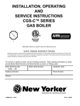
XIII Troubleshooting
Thefollowingpagescontaintroubleshootingchartsforuseindiagnosingcontrolproblems.Tousethesecharts,goto
theboxmarked“Start”atthetopofthechartonpage34or36andfollowtheappropriatepaththoughthechartuntila
boxwithalistofpossiblecausesisreached.Iftheproblemisknowntobewithintheignitionsystem,godirectlytothe
appropriatetroubleshootingguidefortheboiler.Inusingthesecharts,thefollowingshouldbekeptinmind:
1) Thesechartsareonlymeanttobeusedbyaprofessionalheatingtechnicianasanaidindiagnosingcontrolprob-
lems.
2) Whereapplicable,followallprecautionsoutlinedintheappropriatelightinginstructionsonpages28-29.
3) Ingeneral,thesechartsassumethattherearenolooseormiswiredelectricalconnections.Beforeusingthese
charts,inspectallelectricalconnectionsontheboilertomakesurethattheyaretight.Also,checkthewiringonthe
boileragainsttheappropriatewiringdiagraminFigures18-19.
4) Thepossiblecausesattheendofeachbranchinthesechartsarenotlistedinorderoflikelihood.Allcontrolson
theCWIaretestedatleastonceinthemanufacturingprocessandadefectivecontrolorcomponentisgenerallythe
leastlikelycause.Beforereplacingacomponent,trytoruleoutallotherpossiblecauses.
5) Thesetroubleshootingchartsassumethattheventdamperisclosedatthebeginningofthetroubleshootingprocess.
Withthe120voltsappliedtotheboilerandnocallforheat,thedampershouldgototheclosedposition.Ifitdoes
not,dothefollowing:
• Conrmthat120voltsisappliedtotheboilerandthatthereisnocallforheat.
• Makesurethattheswitchonthedamperisinthe“automatic”position.
• Unplugtheharnessfromthedamperandcheckfor24voltsacrosspin#1(blue)andpin#4(yellow).
• Ifvoltageispresent,thedamperisdefectiveorthereisanobstructioninthepathofthedamperblade.
• Ifnovoltageispresent,thereiseitheralooseconnectioninthedamperharnessorthelimitcontrol(L8148E
orL8124E)isdefective.
6) IfthechartsindicatethattheL8148EorL8124Eisdefective,dothefollowingbeforereplacingit:
• Checkfor24voltsacrossTVandZ.Ifnovoltageispresent,thetransformerintheL8148EorL8124Eis
defective.Itispossiblethatthistransformerhasbeendestroyedbyashortcircuitintheboilerwiring.Before
replacingthecontrol,carefullyinspectalllowvoltagewiringontheboilerforplaceswhereitistouchingthe
frameoftheboilerorwiringontheothersideofthetransformer.
• If24voltsispresentacrossTVandZ,checkfor24voltsbetweenTandW.OnL8148Es,ifnovoltageis
present,makesurethatthebrassjumperispresentbetweenWandZandthatthescrewsholdingthisjumper
inplacearebothtight.IftheboilerisequippedwithaL8124E,voltagewillonlybepresentacrossTandW
whenthereisacallforheatANDtheboilerwatertemperaturehighenoughtosatisfythelowlimit.
• Ifnotalreadydone,temporarilyreplacethethermostatacrossTVandTwithajumper.Iftheboilerreswhen
thisisdone,thereisaproblemwiththethermostatorzonewiring.
• If24voltsispresentacrossTandWandtherelayintheL8148EorL8124Edoesnotpullin,therelayinthis
controlisprobablydefective.Inspectthecoilofthisrelayforvisibleheatdamage.Ifsuchdamageisfound,
thereisagoodchancethatasecondtransformerispresentinthethermostatorzonevalvecircuit,resultingin
theapplicationof48voltsacrosstherelaycoil.Inolderbuildings,thistransformermaybehiddeninaloca-
tionfarfromtheboiler.Ifthissecondtransformerexists,itmustbefoundandremovedbeforetheL8148Eor
L8124Eisreplaced.
7)Whencheckingvoltageacrossdamperharnesspins,becarefulnottoinsertthemeterprobesintothepins.Doingso
maydamagethepin,resultinginalooseconnectionwhentheharnessisreconnected.

34
34
Troubleshooting Chart for CWI Boilers Without Tankless Heaters
Caution: Read page 33 before attempting to use this chart
Thermostat
calls for heat
Circulator
start?
120 volts
at
L1
&
L2
?
120 volts at
C1
&
C2
?
N
N
*
Power off
*
Blown fuse or
tripped breaker
*
Miswired or
loose electrical
connection in
120V line
Remove t'stat or
zone valve end
switch wires from
T
&
TV
terminals on
L8148E. Install
temporary jumper
across terminals
T
and
TV
.
Does
circulator
run now?
*
Defective
L8148E-see
Note 6 on page
33.
*
Loose connection in t'stat or
zone valve end switch wiring
*
Defective t'stat or zone valve
end switch
*
T'stat or zone system
miswired-consult t'stat or
zone valve manufacturer's
instructions
Vent
damper
open?
24 volts
across
B
and
R
(limit switch) in
L8148E ?
*
Boiler off on
limit
*
Defective
high limit.
24 volts
between pins
1
&
4
(blue&yellow)and
2
&
4
(orange&yellow) on
damper end of damper
harness? See
Note 7 on page 33.
*
Loose
connection
between
damper
harness and
L8148E
*
Defective
damper
harness.
*
Defective
L8148E
*
Obstruction in
path of damper
blade
*
Defective
damper motor
*
Loose
connection
between damper
harness and
damper
Y
START
24 volts
across
T
&
TV
?
120 volts
across
terminals at
circulator?
*
Seized or
defective
circulator
*
Bad electrical
connection
between
C1
or
C2
and
circulator
N
Y
N
Y
N
Y
Y
Y
N
N
Y
N
Y
Y
N
Y
N
Boiler
Equipped
With
Damper?

35
35
Main
burners
light?
24 volts
across
B1
&
B2
?
Refer to ignition system
troubleshooting chart
(page 38).
*
Defective damper
*
Defective L8148E
*
Defective damper
harness
*
Loose damper
harness connection
*
Obstruction in path
of damper blade
24 volts across
standing pilot gas
valve terminals or
terminals
5
&
6
on
S8600 module?
24 volts
across spill
switch?
*
Chimney blockage
*
Chimney system not
constructed in accordance
with Parts 7 and 10 of
National Fuel Gas Code.
*
Down draft
*
Inadequate combustion air
supply in boiler room
Y
N
N
Y
Y
24 volts
across
rollout
switch?
*
Loose electrical
connection in 24
volt wiring
between
B1
or
B2
and gas valve or
module
*
Rollout switch open.
Replace with exact
replacement (see parts
list). Check for blocked
heat exchanger.
Y
N
N
Y
N
Do burner and
circulator shut
down at end of
call for heat?
END
Pull wire off of
T
terminal on
aquastat. Does
boiler shut down?
*
T'stat or
zone valve
wiring calling
for heat
*
T'stat wires
shorted
*
Internal boiler
wiring
problem,
consult Crown
representative
Do burners
shut down before
gage temp
exceeds high limit
setting +15F?
*
Defective
L8148A
*
Sensing bulb not
bottomed out in
well
N
Y
Y
N
N
Y

36
36
Troubleshooting Chart for CWI Boilers Equipped with Tankless Heaters and Dampers
Caution: Read page 33 before attempting to use this chart
No call for heat,
boiler water
temp. at least
20F below low
limit setting
*
Power off
*
Blown fuse or
tripped breaker
*
Miswired or
loose electrical
connection in
120V line
Vent
damper
open?
24 volts
across
B1
and
TV
on L8124E ?
*
Boiler water
temp above
low limit
setting
*
Defective
L8124E
24 volts
between pins
1
&
4
(blue&yellow)and
2
&
4
(orange&yellow) on
damper end of damper
harness? See
Note 7 on page 33.
*
Loose
connection
between
damper
harness and
L8124E
*
Defective
damper
harness.
*
Obstruction in
path of damper
blade
*
Defective
damper motor
*
Loose connection
between damper
harness and
damper
Main
burners
light?
24 volts across
gray wire on
rollout switch
and
B2
?
Y
Refer to ignition
system
troubleshooting
chart (page 38).
ST ART
*
Defective damper
*
Defective damper
harness
*
Loose damper
harness connection
*
Obstruction in path
of damper blade
24 volts across
standing pilot gas
valve terminals or
terminals
5
&
6
on
S8600 module?
24 volts
across spill
switch?
*
Chimney blockage
*
Chimney system not
constructed in accordance
with Parts 7 and 10 of
National Fuel Gas Code.
*
Down draft
*
Inadequate combustion air
supply in boiler room
Y
N
N
Y
Y
24 volts
across
rollout
switch?
*
Loose electrical
connection in 24
volt wiring
between rollout
switch or
B2
and
gas valve or
module
*
Rollout switch open.
Replace with exact
replacement (see parts
list). Check for blocked
heat exchanger.
Y
N
Y
N
N
Y
N
Y
N
Allow boiler water
temperature to
reach low limit +
differential setting.
Initiate call for heat
24 volts
across
TV
and
Z
?
120 volts
across
L1
&
L2
?
N
* Defective
transformer in
L8124E
Y
Y
N
N
24 volts
across
TV
&
Z
?
*
Defective
L8124E
Y
N

37
37
Circulator
start?
120 volts at
C1
&
C2
?
N
Remove t'stat or
zone valve end
switch wires from
T
&
TV
terminals on
L8124E. Install
temporary jumper
across terminals
T
and
TV
.
Does
circulator
run now?
*
Defective
L8124E-see
Note 6 on page
33.
* Boiler water
temperature
has dropped
below low limit
setting
*
Loose connection in t'stat or
zone valve end switch wiring
*
Defective t'stat or zone
component
*
T'stat or zone system
miswired-consult t'stat or
zone valve manufacturer's
instructions
N
Do burner and
circulator shut
down at end of
call for heat?
END
Pull wire off of
T
terminal on
aquastat. Does
boiler shut down?
*
T'stat or
zone valve
wiring calling
for heat
*
T'stat wires
shorted
* Boiler water
temperature
has dropped
below low limit
setting
*
Internal boiler
wiring
problem,
consult Crown
representative
*
Defective
L8124E
*
Sensing bulb not
bottomed out in
well
*
Seized or
defective
circulator
*
Bad electrical
connection
between
C1
or
C2
and
circulator
Y
N
Y
N
Y
N
Y
Y
Y
N
N
Y
Y
N
Main
burners
light?
*Boiler water
temperature
exceeds high limit
setting
* Defective
L8124E
Y
N
24 volts
across
T
&
TV
?
120 volts
across
terminals at
circulator?
Do burners
shut down before
gage temp
exceeds high limit
setting +15F?

38
38
Spark
across
ignitor/sensor
gap?
Y
Can you
hear
sparking?
*
Defective
ignition
module
*
Break in
spark cable
insulation
*
Break in pilot
porcelain
*
Incorrect
pilot spark gap
*
Loose
connection in
spark cable
*
Loose
ground
connection
N
Pilot
lights?
Y
NN
*
Defective
ignition
module
24 volts
across
PV
&
MV/PV
at gas
valve?
*
Defective EI
wiring
harness.
N
*
Loose connection
in ignition cable or
ground wire
*
Pilot electrode
porcelain cracked
*
Pilot flame not
covering gap
between electrode
and grounding
strap
*
Low gas pressure
at gas valve inlet
*
Defective ignition
module
Main
burner
lights?
N
Y
24VAC
across
terminals
MV
& MV/PV
on
module?
Y
N
N
*
Defective
ignition
module
24 volts
between
MV
&
MV/PV
on gas
valve?
*
Defective
gas valve
*
Defective EI
harness
END
START
(24 volts is present across
24V
and
24V (GND)
on
ignition module but main burners do not light)
N
Y
Y
N
Y
Y
Y
*
Low line pressure
*
Plugged, kinked or leaking
pilot tubing
*
Plugged pilot orifice
*
Gas line not purged of air
*
Defective pilot assembly
*
Defective gas valve
Does
spark stop
when pilot
lights?
24 volts
across
terminals
PV
& MV/PV
at
module?
Intermittent Ignition System Troubleshooting Chart
Caution: Read page 33 before
attempting to use this chart
/