19 X32 RACK DIGITAL MIXER User Manual
5. Topic Guide
5.1 Starting up, shutting down,
and rmware updates
We recommend switching the X32 RACK on before any active sound
reinforcement system is connected. The function called “Safe Main Levels”,
located in the Setup/General Preferences screen, automatically turns down the
main LRC bus levels when booting the console, and also prevents any scene
loading actions from aecting (specically turning up) the main levels.
Synchronization and Sample Rate settings can also be adjusted on the Setup/Cong
page, but please note that changing the sample rate will require a console reboot.
◊ Please Note: Settings under ‘Link Preferences’, ‘Panning Mode’,
and ‘DCA groups’ are stored with the Scene data while all other settings
made on the Setup/Config page are not stored in any preset and will not
be initialized either. Please verify before using the X32 RACK that the
sample rate is set correctly and if the synchronization source is selected
appropriately. If set to external synchronization via one of the two
AES50 ports, while no clock source is actually connected or switched on,
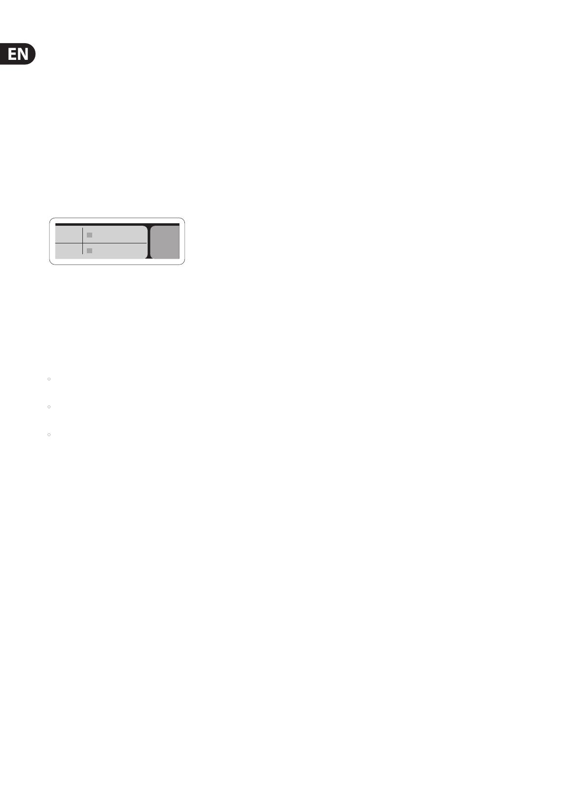
then the corresponding small square icon in the main display’s top row
would be red rather than green. In normal state you should only see
1-4 green squares in the top section depending on the units connected.
Note that if the X32 RACK has previously been in use by somebody else, and you
feel unsure about its actual status, you can reset it to default settings in either of
two convenient ways:
1. While the console is booting up and the “X32” logo appears on the screen,
press and hold the “Scenes / UNDO” button, keeping it depressed until the
console is fully operational and the Home screen is displayed. The console
will now be in the exact same state as it was when rst shipped from the
factory. However, you can immediately revert back to the status the console
was in before being switched o by pressing the Scenes/UNDO button.
2. You can also reset the console any time after booting by pressing
“Setup/Cong” -> “Initialize”.
The X32 RACK regularly stores the console’s status to its onboard ash memory,
sothere is usually nothing wrong with switching it o, and you do not have to
explicitly save the current status. However, when a large number of parameters
have been recently changed, storing all of them to ash can take up to 1 minute,
in a “worst-case” scenario. In order to prevent any errors by losing power during
this type of storage operation, we recommend using the “Safe Shutdown”
function from the Setup/Global page, an operation similar to un-mounting a
USBthumb-drive from your PC.
Updates:
The X32 RACK rmware can easily be updated by performing the following steps:
• Download the new console rmware from the X32 RACK product page onto
the root level of a USB thumb drive
• Plug the USB thumb drive into the front panel USB connector while the
console is turned o
• Hold the USB button depressed while switching the console on.
While booting, the X32 will run a fully automatic rmware update,
which will take 2-3 minutes longer than the regular boot sequence
When no update le is available on the USB drive, or when it is corrupted,
the update mode will remain active, preventing the X32 RACK from booting
regularly. Switch the console o and back on without holding the USB button to
boot the console with the existing rmware.
The USB socket is not suitable for other non-memory USB devices like keyboards,
mice, lamps, etc.
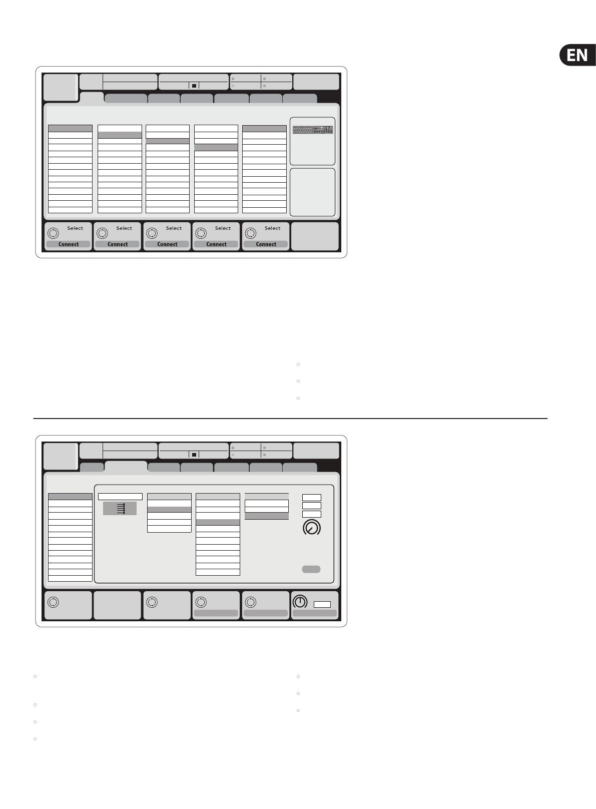
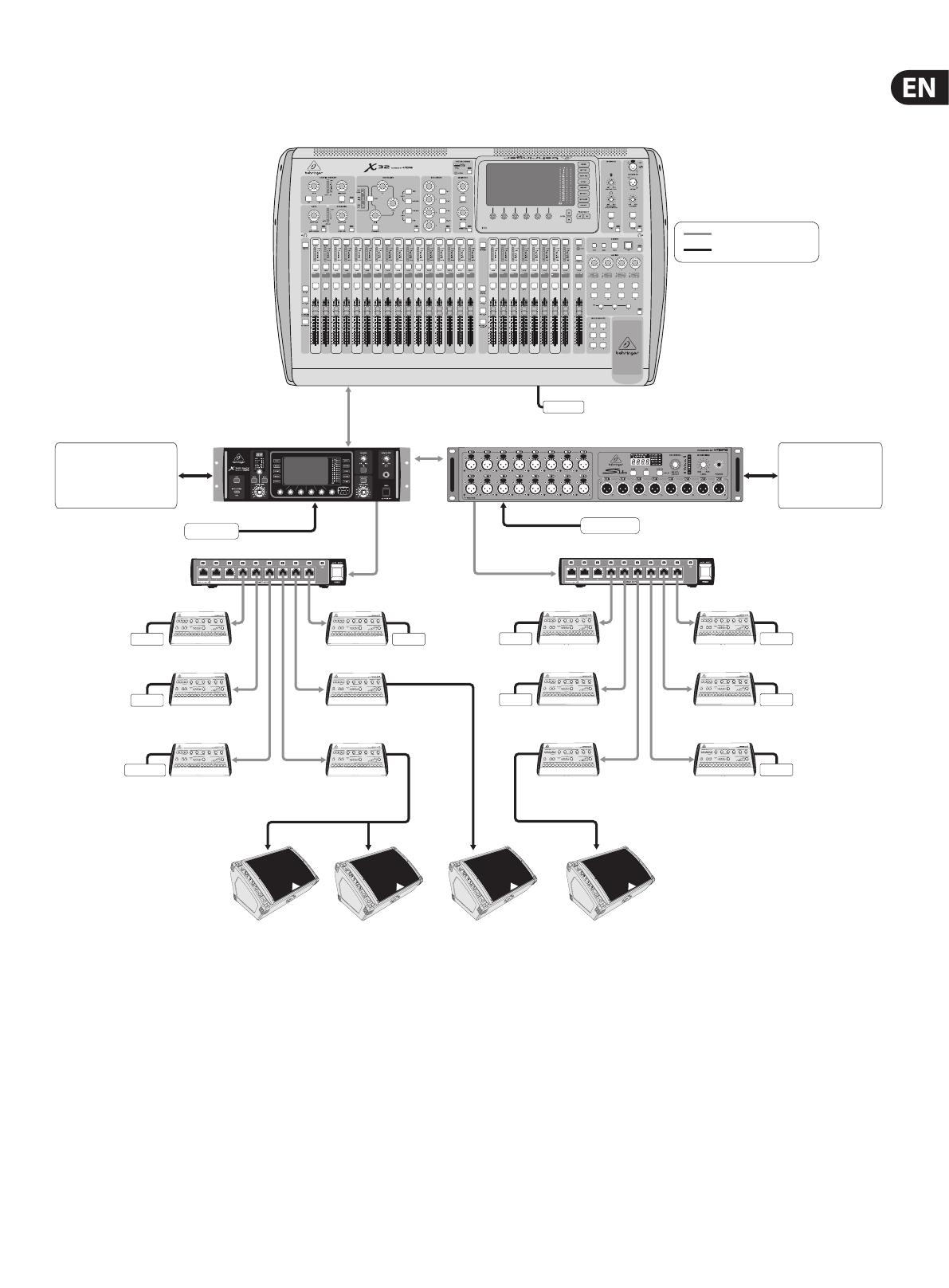
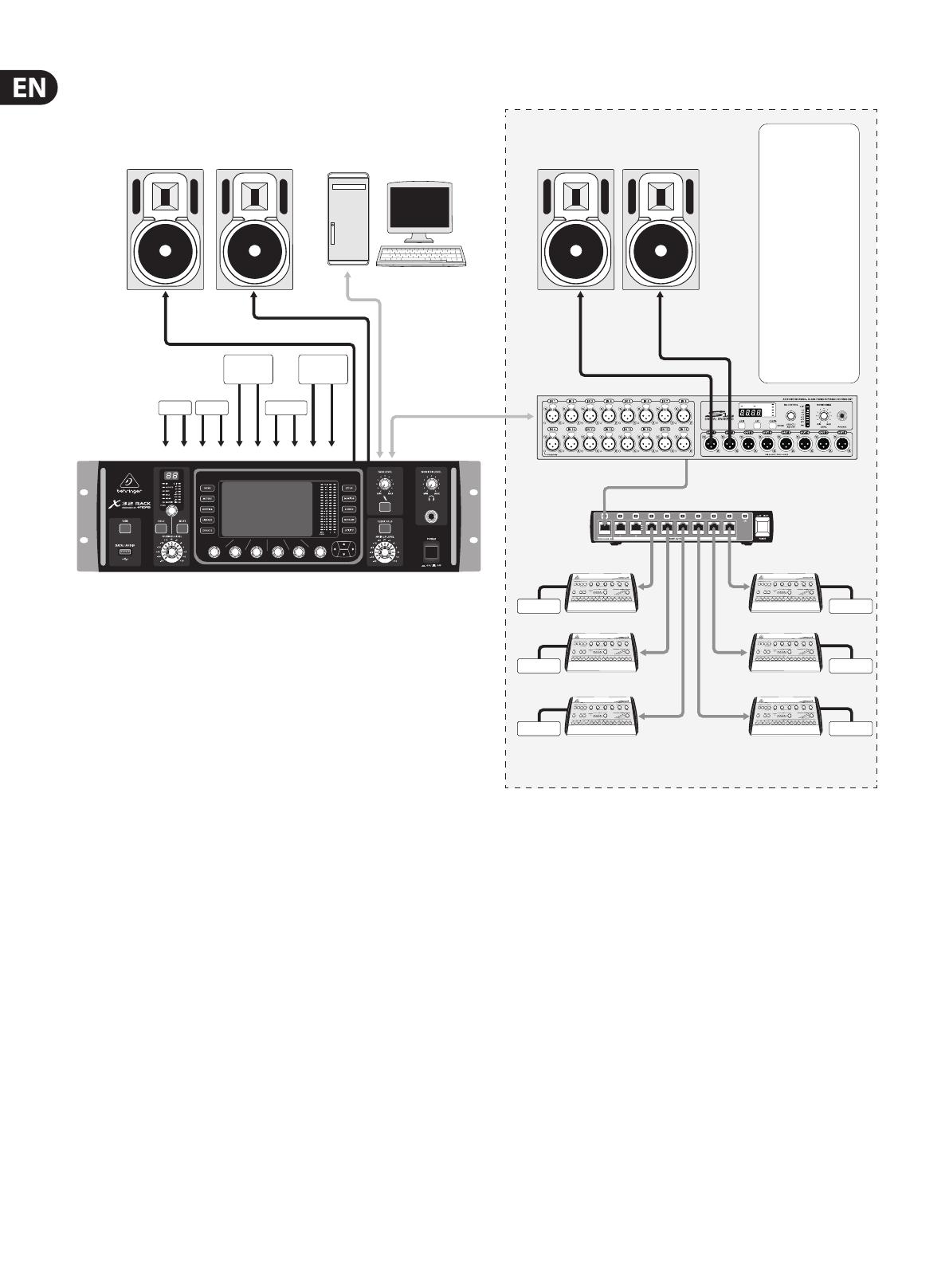
5.2 Default setup for connecting to monitoring
and P.A. systems
The X32 RACK comes pre-congured with the local XLR inputs connected to
input channels 1-16, and XLR outputs 1-6 connected to the mix bus masters 1-6.
The Main LR (stereo) signal is normally put out on XLR outputs 7 and 8.
The Monitoring outputs on ¼" connectors, and the Phones output always carries
either the Monitor Source signal or any solo signal, whenever a solo button is
active. Press the View button in the Monitor section to check or change the solo
and monitoring preferences.
1. Power up the X32 RACK console rst, before any connected power amps or
speakers are switched on.
2. Connect cables to XLR outputs 7 and 8 on the rear panel, connecting the
other ends of the cables to the inputs of your P.A. system. These normally
carry the main stereo bus left and right.
3. All buses or input channels that are to be put out on the main PA system
must have their Main LR Bus switches on. Use the selected channel’s pan
control to place the signal within the main stereo eld, and the channel’s
fader to set the volume.
4. Use the rear panel Monitoring outputs to connect monitor speakers or, ifyou
prefer, use the ¼" output in the front panel to connect your headphones.
Youwill either hear the monitor source signal, which is Main Stereo by
default, or any channel with its solo button being active.
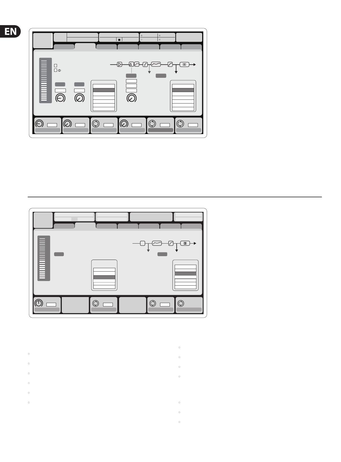
5.3 How do I connect a microphone, process its
signal and send it out to the P.A. system?
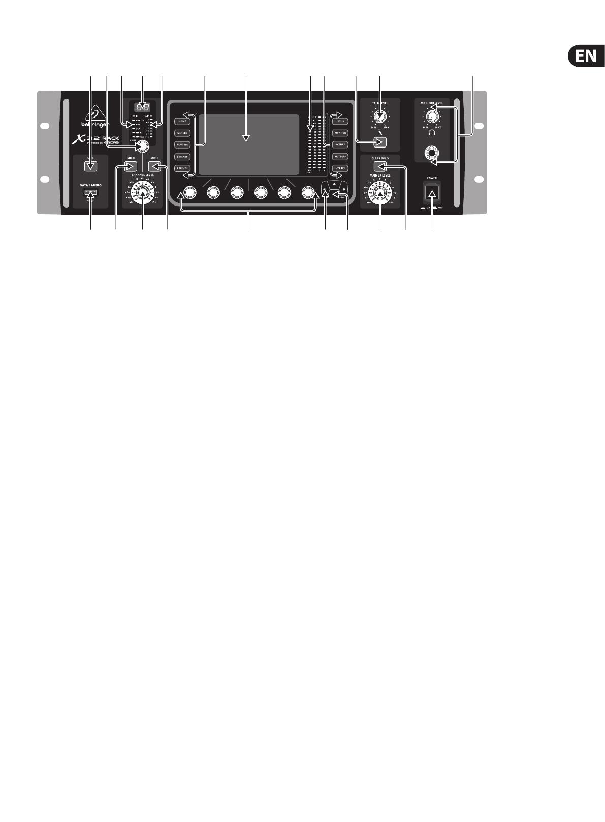
1. Turn the Channel Select knob to select the desired channel and press the
knob to conrm. Make sure the Channel Level knob is turned down.
2. On the Home screen, “home” tab, press the Layer down button and ensure
that the phantom power is disengaged.
3. Connect a microphone to XLR input 1 on the X32 RACK’s rear panel.
4. Engage the phantom power for channel 1 if the microphone requires it
(such as a condenser mic).
Note - It is best practice to mute the respective channels prior to switching
their phantom power supply on or o. Otherwise, the change of charge
may cause an audible popping noise. Gain adjustments might also produce
audible click noise when adjust shortly after having switched phantom
power on or o.
5. On the “home” tab’s rst layer, adjust the Gain knob (1st encoder) to set the
gain as necessary, using the input meter on the left side of the screen as
a guide.
6. Also on the “home” tab, adjust the channel's Gate and Compressor as desired.
7. Press the Page Select right button to access the EQ tab and adjust the
channel's equalization if necessary.
8. Press the 6th encoder to assign the channel to the main bus, then adjust the
encoder to place the signal within the stereo eld.
9. Adjust the Channel Level knob for channel 1 to the 0 dB region, then slowly
turn up the Main LR Level knob until you hear the mic signal amplied
through your P.A. system.