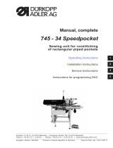
DURKOPP ADLER 745-34 Speedpocket Operating instructions
- Category
- Sewing machines
- Type
- Operating instructions
This manual is also suitable for

745 - 34 Speedpocket
Sewing unit for runstitching
of rectangular piped pockets
Operating Instructions
Installation Instructions
Service Instructions
Instructions for programming DAC
Postfach 17 03 51, D-33703 Bielefeld • Potsdamer Straße 190, D-33719 Bielefeld
Telefon +49 (0) 521 / 9 25-00 • Telefax +49 (0) 521 / 9 25 24 35 • www.duerkopp-adler.com
Ausgabe / Edition: Änderungsindex Teile-Nr./Part.-No.:
06/2007 Rev. index: 02.0 Printed in Federal Republic of Germany 0791 745171
1
2
3
4

All rights reserved.
Property of Dürkopp Adler AG and copyrighted. Reproduction or publication of the content in any manner,
even in extracts, w ithout prior written permission of Dürkopp Adler AG, is prohibited.
Copyright ©
Dürkopp Adler AG - 2007

Foreword
This instruction manual is intended to help the user to become familiar
with the machine and take advantage of its application possibilities in
accordance with the recommendations.
The instruction manual contains important information on how to
operate the machine securely, properly and economically. Observation
of the instructions eliminates danger, reduces costs for repair and
down-times, and increases the reliability and life of the machine.
The instruction manual is intended to complement existing national
accident prevention and environment protection regulations.
The instruction manual must always be available at the machine/sewing
unit.
The instruction manual must be read and applied by any person that is
authorized to work on the machine/sewing unit. This means:
– Operation, including equipping, troubleshooting during the work
cycle, removing of fabric waste,
– Service (maintenance, inspection, repair) and/or
– Transport.
The user also has to assure that only authorized personnel work on the
machine.
The user is obliged to check the machine at least once per shift for
apparent damages and to immediatly report any changes (including the
performance in service), which impair the safety.
The user company must ensure that the machine is only operated in
perfect working order.
Never remove or disable any safety devices.
If safety devices need to be removed for equipping, repairing or
maintaining, the safety devices must be remounted directly after
completion of the maintenance and repair work.
Unauthorized modification of the machine rules out liability of the
manufacturer for damage resulting from this.
Observe all safety and danger recommendations on the machine/unit!
The yellow-and-black striped surfaces designate permanend danger
areas, eg danger of squashing, cutting, shearing or collision.
Besides the recommendations in this instruction manual also observe
the general safety and accident prevention regulations!

General safety instructions
The non-observance of the following safety instructions can cause
bodily injuries or damages to the machine.
1. The machine must only be commissioned in full knowledge of the
instruction book and operated by persons with appropriate training.
2. Before putting into service also read the safety rules and
instructions of the motor supplier.
3. The machine must be used only for the purpose intended. Use of
the machine without the safety devices is not permitted. Observe all
the relevant safety regulations.
4. When gauge parts are exchanged (e.g. needle, presser foot, needle
plate, feed dog and bobbin) when threading, when the workplace is
left, and during service work, the machine must be disconnected
from the mains by switching off the master switch or disconnecting
the mains plug.
5. Daily servicing work must be carried out only by appropriately
trained persons.
6. Repairs, conversion and special maintenance work must only be
carried out by technicians or persons with appropriate training.
7. For service or repair work on pneumatic systems, disconnect the
machine from the compressed air supply system (max. 7-10 bar).
Before disconnecting, reduce the pressure of the maintenance unit.
Exceptions to this are only adjustments and functions checks made
by appropriately trained technicians.
8. Work on the electrical equipment must be carried out only by
electricians or appropriately trained persons.
9. Work on parts and systems under electric current is not permitted,
except as specified in regulations DIN VDE 0105.
10. Conversion or changes to the machine must be authorized by us
and made only in adherence to all safety regulations.
11. For repairs, only replacement parts approved by us must be used.
12. Commissioning of the sewing head is prohibited until such time as
the entire sewing unit is found to comply with EC directives.
13. The line cord should be equipped with a country-specific mains
plug. This work must be carried out by appropriately trained
technicians (see paragraph 8).
It is absolutely necessary to respect the safety
instructions marked by these signs.
Danger of bodily injuries !
Please note also the general safety instructions.

Index Page:
Part 4: Programming Instructions DAC Cl. 745-34 Speedpocket
Program version A 02.0
1. Structure of menu ............................................ 3
2. Operation
2.1 Editingthepocketprogram ....................................... 5
2.2 Editing the sequence ........................................... 6
3. Setting programs of the machine
3.1 Indicating / Deleting the counter for the bobbin thread quantity .................. 7
3.2 Setting the counter for the bobbin thread quantity .......................... 7
3.3 Testing the feeding process ....................................... 7
3.4 Step-by-stepmode ............................................ 8
3.5 Dongle menu ................................................ 9
4. Multitest
4.1 Testingtheoutputelements....................................... 12
4.2 Testing the input elements manually .................................. 12
4.3 Testing the input elements automatically ............................... 12
4.4 TestingtheROM ............................................. 13
4.5 TestingtheRAM.............................................. 13
4.6 Testingthesewingmotor......................................... 13
4.7 Displayingthefaultrecorder....................................... 13
4.8 Testingthecornerknives......................................... 14
4.9 Testingthecenterknifeactivation ................................... 14
4.10 Settingthelight-barrierfortheflap................................... 14
4.11 Optional equipment - Setting the thread monitor ........................... 15
4.12 Optional equipment - Setting the 2
nd
lightbarrierfortheflap ................... 15
5. Table Seam Parameters......................................... 16
6. Machine parameters ........................................... 18
7. Error messages/ Functional indications .............................. 19
8. Input elements .............................................. 24
9. Output elements ............................................. 24


1. Structure of menu
Switch-on
Multitest 901 Output elements
“P” and “ç” 902 Input elements, manual
903 Input elements, automatic
904 Testing the ROM
905 Testing the RAM
906 Testing the sewing motor
907 Displaying the fault recorder
950 Testing the corner knives
951 Testing the center knife
952 Setting the light-barrier for the flap
953 Setting the thread monitor
954 Setting the 2nd light barrier for the flap
“P” and “è” Initializing the parameters Code : 2548
400 Machine parameters
Initializing the parameters
500 501 Machine parameters
502 Pockets
503 Sequence
504 All parameters
600 Displaying the counter of pieces
Produced
Sewing mode
“P” and “F” Setting programs
301 Indicating / Deleting
the counter for the bobbin thread quantity
302 Setting the bobbin thread counter
303 Testing the feeding process
304 Step-by-step mode
305 Dongle
“P” Editing the current seam parameters,
100 -136
“F” short/long Sequence, short = on/off,
long = editing
“ESC” and “ç” Indicating / Deleting the piece counter
“ESC” and “ê” Center knife on/ off
“ESC” and “é” Corner knife on/ off
“ESC” and “è” Stacker on/ off
“é”or“ê” Changing the current seam length
“ç”or“è” Changing over to the next s eam
program
3

2. Operation
If neither the key ( “P” and “è” ) nor the key ( “ P” and “ç” )
is pressed within 2 seconds after switching on, the program
starts the sewing mode.
First the machine has to carry out the reference run initiated
by the pedal.
Until then the display will flash.
rEF
4

2.1 Editing the pocket program
When the machine is in basic position and in the sewing mode and the
key “P” is actuated, you get into the level for editing the current pocket
program.
In case the feeding process has started already, this is not possible.
For this purpose the feeding operation would have to be cancelled so
that the machine is in its basic position again.
Selecting the seam parameter
100 23
current parameter value
The parameter number flashes, select with the keys”é“ and ”ê“.
After “OK” the display changes, e.g. ->
Editing the seam parameter
108 054
One digit of the value 054 flashes and can be changed with the k eys
”é“ and ”ê“andsavedwith“OK”.
“ESC” -> no alteration and back.
With the keys “ ¬ “or“®” you can change to the next editable d igit.
Parameter No. 108
Initializing the pocket program
1P P I n I
After a short actuation of “F” the display changes to this submenu.
The initialization is carried out with “OK” and aborted with “ESC”. With
the initialization a pocket program with standard values is loaded.
9P P I n I
With a long actuation of “F” all 9 seam pograms are initialized.
Afterwards the display changes to the mode for selecting a seam
parameter in the current seam program again.
5

2.2 Editing the sequence
When in the sewing mode key “F” is pressed longer than 2 seconds,
you get into the level for editing the sequence.
With a short actuation of “F” the sequence is switched on or off.
1
At the beginning of editing the sequence the current sequence is
cancelled and the first digit after the “S” flashes.
123 4 5 67
With the keys “ “and”¯“ the program number can be altered. With the
keys”¬“or“®” you change to the next position.
After actuating the key ”¬” the position right of the flashing digit is
cancelled. Thus, the number of seam programs per sequence is
determined. Max. 7 seam programs can be entered per sequence.
With “OK” the editing of the sequence is finished and the display goes
back to the sewing mode with sequence.
2.3 Piece counter
When actuating “ESC” and “¬” in the sewing mode, the daily piece
counter is displayed.
S 1054
With a short touch of key “ESC” you change to the sewing mode again.
With a long actuation of “OK” the counter is set to “0” and the display
“0” appears until the “ESC ”-key is actuated.
6

3. Setting programs of the machine
The setting programs can be reached from the sewing mode by
actuating “P” and “F” simultaneously
List of setting programs:
30 1 Indicating the counter for the bobbin thread quantity / Deleting
302 Setting the counter for the bobbin thread quantity
303 Testing the feeding process
304 Step-by-step mode
The various setting programs can be selected with the keys “ “ and
” ¯“, ac tivated with “OK” and quitted with “ESC”.
30x ____
After a ctuating “ OK” the selected program is activated.
3.1 Indicating the counter for the bobbin thread quantity / Deleting
301 12 34
The current value can be reset to the programmed maximum value by
a long actuation of “OK”.
The indicated value has to be multiplied by 10.
3.2
Setting the counter for the bobbin thread quantity
302 1 2 34
The value flashes and can be altered with the keys ““ and ” ¯“. When
actuating “OK” the value is s aved and a setting program can be
selected again.
The indicated value has to be multiplied by 10.
At the value 0 the bobbin thread counter is switched off.
3.3 Testing the feeding process
303 on
After a long actuation of “OK” the program changes to the sewing
process.
After the reference run the feeding process is carried out as in the
sewing program. When actuating the pedal in inching operation the
transport carriage runs in its rear position. The feeding clamps are
lifted and the flap clamps open. The process can be started anew or
quittedwith“ESC”.
Switch the machine off in order to quit the program.
7

3.4 Step-by-step mode
304 StEP
Withalongactuation of “OK” the program changes to the sewing
process.
At the stops at the seam beginning and seam end the following display
appears:
SP PEd
After stepping on the pedal the sewing process continues up to the
next stop.
While the sewing program is running, the display changes to the
normal sewing process again.
Switch the machine off in order to quit the program.
8

3.5 Dongle Menu
Important:
To save the parameters you will need an empty dongle. It can be
bought at the sales point of Dürkopp Adler AG under the following part
number 9835 901005.
305
After actuating the “OK” key, the display display changes to a lower
level. Using the key “¬” will bring it back, one level higher. For other
choices within the menu use the ““ and ”¯“keys.
At the same time, the right half of the display flashes.
If no dongle is connected at the plug connection “X110“, the message
“Info 4301“ will be displayed. The left and right half of each menu item
will flash during the data transmission.
Menu item display dongle content
do dir
The following displays may appear after actuating the “OK”key
Data dongle, e.g. for Cl. 745-34S
(to save the parameters)
d745 -34S
Boot dongle, e.g. for Cl. 745-34S
b745 -34S
Empty Dongle (not formatted)
Info 4302
(The dongle has to be formatted first, check menu item format dongle).
Exit and go back to the Menu item display dongle content by
actuating the “OK“key.
Menu item load the machine parameter
do L PPP
Confirmation
InFo 4323
After actuating the “OK” key, the machine parameter will be loaded
from the dongle to the control.
Exit and go back to the Menu item load the machine parameter by
actuating the “ESC“key.
If the dongle contains no machine parameter, the message “Info 4325“
displays, it has to be confirmed by actuating the “OK“key.
9

Menu item load pocket program and sequence
do L 9PS
Confirmation
InFo 4324
After actuating the “OK” key, the pocket parameter and the sequence
will be loaded from the dongle to the control.
Exit and go back to the Menu item load pocket program and
sequence by actuating the “ESC“key.
If the dongle contains no pocket program, the message “Info 4326“
displays, it has to be confirmed by actuating the “OK“key.
Menu item save machine parameter
do S PPP
Confirmation
InFo 4321
After actuating the “OK” key, the machine parameter of the sewing unit
will be saved onto the dongle.
Exit and go back to the Menu item save machine parameter by
actuating the “ESC“key.
Menu item save pocket program and sequence
do S 9PS
Confirmation
InFo 4322
After actuating the “OK” key, the pocket parameters and the sequence
will be saved onto the dongle.
Exit and go back to the Menu item save pocket program and
sequence by actuating the “ESC“key.
Menu item format dongle
do For
Confirmation
InFo 4320
After actuating the “OK” key, the dongle will be formatted.
Format cancel and go back to the Menu item format dongle by
actuating the “ESC“key.
10

During the format process the display flashes
d745 For
When the format process ends, the Menu item format dongle is
displayed again.
Important:
The data on the dongle will be erased through the formatting.
A formatting of the dongle is necessary, if in the Menu item display
dongle content does not display
, the following.
d745 -34S
but for example
Boot-Dongle, e.g. for cl. 745-34S
b745 -34S
Empty Dongle
Info 4302
11

4. Multitest
The Multitest programs can be reached by switching on and actuating
“P” and “ç” simultaneously.
List of programs:
901 Testing the output elements
902 Testing the input elements manually
903 Testing the input elements automatically
904 Testing the ROM
905 Testing the RAM
906 Testing the sewing motor
907 Displaying the fault recorder
950 Testing the corner knives
951 Testing the center knife
952 Setting the light-barrier for the flap
953 Setting the thread monitor
954 Setting the 2nd light barrier for the flap
4.1 Testing the output elements
901 ____
After “OK” the display changes to
Y01 0
In the left half o f the display the number of the output element flashes,
the right half shows its state:
0=off,
1 = on.
With the keys “ é” and “ê” the number of the output element can be
selected.
With “OK” this output element is switched on or off.
When changing over to the next output element the state of the
preceding one remains unchanged.
4.2 Testing the input elements manually
902 ____
After “OK” the display changes to
S01 0
In the left half of the display the number of the input element flashes.
In the right half the state is indicated;
0 or 1 respectively.
With the keys “ é” and “ê” the number of the input element can be
selected.
12

4.3 Testing the input elements automatically
903 ____
After “OK” the display changes to
E01 0
In the right half the state of the input element is indicated which
changed last.
4.4 Testing the ROM
904 ____
buSY
Display during the test
Display after the test
check sum, e.g.
1=OK 0=Error
1C3F H 1
4.5 Testing the RAM
905 ____
buSY
Display during the test
Display after the test
1=OK 1=OK
0 = Error 0 = Error
R1.1r2.1
4.6 Testing the sewing motor
906 ____
After “OK” the display changes to
n0
With the keys “+” and “-” the speed can be c hanged in steps of
100 rpm.
4.7 Displaying the fault recorder
907 ____
1Er 1052
The last 10 errors will be displayed.
For scrolling, use the keys “+” and “-”.
13

4.8 Testing the corner knives
950 123
In the right LED field the current seam length of L1 flashes.
With key “P” the corner knives are moved up and down.
4.9 Checking the center knife activation
951 on
The center knife is switched on and off with key “F”.
4.10 Setting the light-barrier for the flap
–
Before activating the program, swing out the folding station.
–
Place the fabric under the feeding clamp.
952 ____
After actuating the “OK“ key, the switching status of the light-barrier to
the flap-scanning will be shown in the right half of the display flashing.
Reflecting ® LS 1
No reflection ® LS 0
952 LS 1
Activate the following output elements:
Lower the feeding clamps left and right
Close the folding sheets
Close the flap clamps
–
Pull the feeding clamp to the feeding area.
–
Align the light-barrier with the center of the reflecting foil.
Please check the area from the s eam beginning to the seam end
on the clamp.
–
Determine the distance between the switch actuation point of the
light-barrier to the needle. For this purpose lay a pattern made of
paper having the same size as the flap under the flap clamps.
Then push the feeding clamps from the feeding area to the
machine head until the light-barrier has no longer reflexion. Then
measure the distance between the front edge of the pattern to the
needle.
–
Enter the distance between the switch actuation point of the
light-barrier and the needle in the machine parameters. Switch the
machine off, when swithching it on strike the “P“ and “®“keys
simultaneously in order to switch over to the programming level
(400) for machine parameters (Code 2548). In the menu item 406
enter the distance in 1/10 mm.
14

Orange LED on = reflection available
Orange LED off = no reflection
Green LED on = stable switching signal
If the green LED does not shine, the light-barrier should be cleaned,
readjusted, replaced or a new reflecting foil should be fitted.
4.11 Optional equipment - Setting the thread monitor
953 ____
(see operating instructions)
4.12 Optional equipment - Setting the 2nd light barrier for the flap
–
Before activating the program, swing out the folding station.
–
Place the fabric under the feeding clamp.
954 ____
After actuating the “OK“ key, the switching status of the light-barrier to
the flap-scanning will be shown in the right half of the display flashing.
Reflecting ® LS 1
No reflection ® LS 0
954 LS 1
Activate the following output elements:
Lower the feeding clamps left and right
Close the folding sheets
Close the flap clamps
–
Pull the feeding clamp to the feeding area.
–
Align the light-barrier with the center of the reflecting foil.
Please check the area from the s eam beginning to the seam end
on the clamp.
–
Determine the distance between the switch actuation point of the
light-barrier to the needle. For this purpose lay a pattern made of
paper having the same size as the flap under the flap clamps.
Then push the feeding clamps from the feeding area to the
machine head until the light-barrier has no longer reflexion. Then
measure the distance between the front edge of the pattern to the
needle.
–
Enter the distance between the switch actuation point of the
light-barrier and the needle in the machine parameters. Switch the
machine off, when swithching it on strike the “P“ and “®“keys
simultaneously in order to switch over to the programming level
(400) for machine parameters (Code 2548).
The menu item 409 must be activated.
In the menu item 410 enter the distance in 1/10 mm.
15

5. Table Seam Parameters
Press key “P” in the main level.
In the programming level initialize key “ F” -> current program and
“F-Long” all seam programs.
Number Description Minimum Maximum Standard
Menu item value value value
100 Seam length mm 20 180 180
101 Stacker on / off on
102 Center knife on / off on
103 Center knife correction seam beginning 1/10 mm -9,9 9,9 0
104 Center knife correction seam end 1/10 mm -9,9 9,9 0
105 Corner knife on / off on
106 Corner knife correction seam beginning 1/10 mm -20 20 0
107 Corner knife correction seam end 1/10 mm -20 20 0
108 Stitch length 1/10 mm 2,0 3,0 2,5
109 Sewing motor speed 2000 3000 2750
110 Sewing motor soft start on / off on
111 Sewing motor number of soft start stitches 1 20 2
112 Sewing motor soft start speed 500 900 900
113 Clamping mode 0
0 = Lower left and right feeding clamp
simultaneously
1 = Lower left feeding clamp first
2 = Lower right feeding clamp first
114 Positioning point 0
0 = front
1 = center
2 = rear
115 Positioning point offset mm 1 170 90
116 Type seam tightening seam beginning 1
0=Bartack
1 = Condensed stitches
117 Number of condensed stitches seam beginning 1 10 4
118 Stitch length condensed stitches / Bartack
Seam beginning 1/10 mm 0,5 3,0 1,0
119 Number of bartacks seam beginning 1 5 3
120 Type seam tightening seam end 1
0=Bartack
1 = Condensed stitches
121 Number of condensed stitches seam end 1 10 4
122 Stitch length condensed stitches / Bartack
Seam end 1/10 mm 0,5 3,0 1,0
123 Number of bartacks seam end 1 5 3
124 Material feed type 2
0 = Material runs to the loading position
1 = Material runs to the stacking position
2 = no run, in stacking position
16
Page is loading ...
Page is loading ...
Page is loading ...
Page is loading ...
Page is loading ...
Page is loading ...
Page is loading ...
Page is loading ...
-
 1
1
-
 2
2
-
 3
3
-
 4
4
-
 5
5
-
 6
6
-
 7
7
-
 8
8
-
 9
9
-
 10
10
-
 11
11
-
 12
12
-
 13
13
-
 14
14
-
 15
15
-
 16
16
-
 17
17
-
 18
18
-
 19
19
-
 20
20
-
 21
21
-
 22
22
-
 23
23
-
 24
24
-
 25
25
-
 26
26
-
 27
27
-
 28
28
DURKOPP ADLER 745-34 Speedpocket Operating instructions
- Category
- Sewing machines
- Type
- Operating instructions
- This manual is also suitable for
Ask a question and I''ll find the answer in the document
Finding information in a document is now easier with AI
Related papers
-
 Duerkopp Adler 267_valid_till_March_2016 User manual
-
 Duerkopp Adler 269_valid_till_May_2017 User manual
-
 Duerkopp Adler 366 Operating instructions
-
 Duerkopp Adler 745-35 S User manual
-
 Duerkopp Adler 745-35 User manual
-
Adler 745-34 Operating instructions
-
DURKOPP ADLER 745-34-1/-3 Program
-
 Duerkopp Adler 745-35 Operating instructions
-
 Duerkopp Adler 745-35 Operating instructions
-
Beisler 100-68 Owner's manual
Other documents
-
 Adler AG 745-34 Speedpocket User manual
-
 Duerkopp Adler 100-69 Operating instructions
-
 Duerkopp Adler 911-210-10 User manual
-
Duerkopp Adler 540 User manual
-
 Duerkopp Adler 755 S Operating instructions
-
 Duerkopp Adler 867-M PREMIUM User manual
-
 Duerkopp Adler 755_B Operating instructions
-
 Duerkopp Adler 755 A Operating instructions
-
Duerkopp Adler 540 Operating instructions
-
 Duerkopp Adler 867-M PREMIUM User manual


