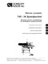
745 - 35 D
Operating Manual

All rights reserved.
Property of Dürkopp Adler AG and protected by copyright. Any reuse of these contents, includ-
ing extracts, is prohibited without the prior written approval of Dürkopp Adler AG.
Copyright © Dürkopp Adler AG 2013
IMPORTANT
READ CAREFULLY BEFORE USE
KEEP FOR FUTURE REFERENCE

Table of Contents
Operating manual 745-35 D Version 01.0 - 07/2013
1
1 About this operating manual.....................................................3
1.1 Scope of application of the operating manual ..............................3
1.2 For whom is this operating manual?.............................................3
1.3 Representational conventions – Symbols and characters............4
1.4 Other documents..........................................................................4
1.5 Liability..........................................................................................4
1.5.1 Transportation ..............................................................................5
1.5.2 Intended use.................................................................................5
2 Performance description ...........................................................7
2.1 Features .......................................................................................7
2.2 Declaration of conformity..............................................................8
2.3 Optional equipment ......................................................................8
2.4 Subclasses .................................................................................13
2.4.1 745-35 S.....................................................................................13
2.4.2 745-35 A.....................................................................................13
2.4.3 745-35 B.....................................................................................14
2.4.4 745-35 D.....................................................................................14
2.4.5 745-35 F.....................................................................................15
2.5 Technical data............................................................................16
3 Safety instructions ...................................................................17
3.1 Basic safety instructions.............................................................17
3.2 Signal words and symbols used in warnings..............................18
4 Machine description 745-35.....................................................21
4.1 Sewing unit 745-35.....................................................................21
4.2 Software description...................................................................22
5 Operating...................................................................................25
5.1 Swing the folding station aside..................................................25
5.2 Pushing the covering hood back and removing the
fabric sliding sheets....................................................................26
5.3 Tilting the machine head up .......................................................28
5.4 Needles and threads ..................................................................30
5.5 Threading in the needle thread...................................................33
5.6 Winding on the bobbin thread.....................................................36
5.7 Residual thread monitor: ............................................................37
5.8 Changing the bobbins................................................................38
5.9 Thread tension............................................................................40
5.10 Stacking control..........................................................................42
5.11 Corner knife station rectangular pocket corners........................43
5.11.1 Swinging the corner knife station out / in...................................43
5.12 Corner knife station slanted pocket corners...............................44
5.12.1 Swinging the corner knife station out / in....................................44
5.13 Setting the corner knife...............................................................46
5.14 Reference position, Starting the sewing cycle, Quick stop.........47
5.15 Flap and Piping Projection..........................................................49
5.16 Piping strip length.......................................................................50
5.17 Working method D......................................................................51
5.17.1 Folder monitoring........................................................................56
5.18 Functions and operation of the optional equipment....................58

Table of Contents
Operating manual 745-35 D Version 01.0 - 07/2013
2
5.18.1 Stacker .......................................................................................58
5.18.2 Roll-off device.............................................................................62
5.18.3 Tape feed and automatic cutting................................................63
5.18.4 Vacuum device...........................................................................67
5.19 Maintenance...............................................................................68
5.19.1 Cleaning .....................................................................................68
5.19.2 Weekly lubrication ......................................................................71
6 Installation.................................................................................73
6.1 Delivery scope............................................................................73
6.2 Installing the sewing unit ............................................................74
6.2.1 Transportation ............................................................................74
6.2.2 Removing the transport securing devices...................................75
6.2.3 Setting the working height..........................................................76
6.2.4 Connecting the foot pedal...........................................................77
6.2.5 Adjusting the foot pedals............................................................78
6.3 Attaching the machine parts removed for shipping.....................79
6.3.1 Thread reel holder......................................................................79
6.3.2 Fastening the control panel and the bobbin winder....................80
6.3.3 Table extensions (optional equipment).......................................81
6.4 Electrical connection...................................................................83
6.4.1 Connecting the control panel DACIII..........................................83
6.4.2 Connecting a separate winder....................................................84
6.5 Pneumatic connection................................................................85
6.5.1 Connecting the maintenance unit for compressed air ................86
6.6 Connection to the in-house vacuum unit....................................87
6.7 Oil lubrication..............................................................................88
6.8 Putting into operation..................................................................90
6.9 Installation of the software..........................................................91
6.9.1 General information....................................................................91
6.9.2 Loading the program ..................................................................92
6.9.3 Dongle-Update via Internet.........................................................93
6.10 Customer service........................................................................93
7 Decommissioning.....................................................................95
8 Disposal.....................................................................................97

About this operating manual
Operating manual 745-35 A Version 01.0 - 07/2013
3
1 About this operating manual
The operating manual for the 745-35 sewing unit was compiled with the
utmost care. It contains information and notes in order to make long-term
and reliable operation possible.
Should you notice any discrepancies or if you have improvement re-
quests, then we would be glad to receive your feedback, Chapter 6.10
Customer service.
Please regard the operating manual as part of the product and keep it in
a safe place where it can be easily accessed. Read the operating manual
completely prior to using the unit for the first time. Only pass the product
on to third parties together with the operating manual.
1.1 Scope of application of the operating manual
This operating manual describes the set-up and intended use of the 745-
35 sewing unit.
1.2 For whom is this operating manual?
The operating manual is intended for:
• Machine operators:
This group of employees has been trained in operating the machine
and can access the operating manual. Specifically Chapter 5 of
the Operating manual is important for this group of employees.
• Technicians:
This group of employees has the appropriate technical training
allowing them to perform maintenance on the sewing unit or to repair
faults. Specifically Chapter 6 of the Installation instructions is
important for this specialized staff.Service instructions are supplied
separately.
With regard to minimum qualification and other requirements to be met by
the personnel, please also observe Chapter 3 of the Safety instruc-
tions.

About this operating manual
4
Operating manual 745-35 A Version 01.0 - 07/2013
1.3 Representational conventions – Symbols and characters
Different information is depicted or highlighted in this operating manual by
the following characters for easier and quicker understanding:
Safety Important warnings for the user of the machine are specifically marked.
Because safety constitutes an area of major importance, hazard symbols,
levels of risk, and their signal words are described separately in Chap-
ter 3 of the Safety instructions.
Location informa-
tion
Information on where something is positioned using the terms “right” or
“left” must always be regarded from the operator's point of view if the figure
gives no other obvious indication for determining the location.
1.4 Other documents
The device contains built-in components from other manufacturers. The
respective manufacturers have carried out hazard assessments for these
purchased parts and confirmed compliance of the design with the applica-
ble European and national regulations. The intended use of the built-in
components is described in the corresponding manuals of the manufac-
turers.
1.5 Liability
All information and notes in this operating manual have been compiled in
accordance with the latest technology and the applicable standards and
regulations.
The manufacturer cannot be held liable for any damage due to:
• Damage during transport
• Failure to observe the operating manual
• Improper use
• Unauthorized modifications to the machine
• The deployment of untrained personnel
• Using spare parts not approved
Symbol/character Meaning
•
Lists are identified by bullet points.
1.
2.
Instructions are numbered and have to be performed in the
specified order.
References to further information in this operating manual or
other documents are identified by this symbol.

About this operating manual
Operating manual 745-35 A Version 01.0 - 07/2013
5
1.5.1 Transportation
Dürkopp Adler cannot be held liable for any damage during transport.
Check the delivered product immediately after receiving it. Report any
damage to the last transport manager. This also applies if the packaging
is not damaged.
Keep the machines, devices and packaging material in the condition they
were at the time when the damage was identified. That secures any claims
towards the transport company.
Report all other complaints to Dürkopp Adler immediately after receiving
the product.
1.5.2 Intended use
The Dürkopp Adler 745-35 is for sewing light to moderately heavy materi-
al. Light to moderately heavy material requires a needle strength of 80-
110 Nm.
The machine is only intended for processing dry material. The material
must not contain any hard objects.
The seam is produced using core spun threads, polyester fibers, or cotton
threads.
The sewing machine is intended for industrial use.
The machine may only be set up and operated in dry conditions on well-
maintained premises. If the machine is operated on premises that are not
dry and well-maintained, then further measures may be required which
must be compatible with EN 60204-31:1999.
Only authorized/trained persons may work on the machine.
The manufacturer will not be held liable for damage resulting from improp-
er use.
Danger due to high voltage, crushing and
sharp objects.
Improper use can result in injuries.
Please follow all instructions in the manual.
WARNING
Improper use could result in material damage.
Please follow all instructions in the manual.
ATTENTION!

About this operating manual
6
Operating manual 745-35 A Version 01.0 - 07/2013

Performance description
Operating manual 745-35 A Version 01.0 - 07/2013
7
2 Performance description
The Dürkopp Adler 745-35 is a sewing unit for the automatic runstitching
of piped, flap and welt pocket openings with rectangular pocket corners.
The piping strips and additional parts are fed manually.
2.1 Features
Machine head
• Twin needle lockstitch version
• Large vertical hooks
• Externally driven center knife, speed and circuit timing programmable
• Thread trimming device for needle and hook threads
• Needle thread monitor
• Photoelectric remaining thread monitor for the hook threads
• Sewing drive as DC direct drive
Step motors for material feed
• The step motor technology results in short machine cycle times and
guarantees an absolutely precise corner incision.
• Thus, it contributes to a pocket quality as yet unprecedented, com-
bined with high productivity.
New generation of DAC III controls (DÜRKOPP ADLER Control)
• The comprehensive test and monitoring system MULTITEST is inte-
grated in the DACIII.
• A control unit does the control tasks, monitors the sewing cycle and
signals operating faults and malfunctions on the control panel.
Sewing equipment and folders
Information concerning the sewing equipment and folders for the various
applications can be taken from the sewing equipment sheets of class 745-
35.
Please direct your inquiries to the DÜRKOPP-ADLER sales offices.

Performance description
8
Operating manual 745-35 A Version 01.0 - 07/2013
2.2 Declaration of conformity
The machine complies with the European regulations specified in the dec-
laration of conformity or in the installation declaration.
2.3 Optional equipment
By means of a flexible system of optional equipment the sewing unit can
be equipped optimally and economically corresponding to the respective
application.
= Standard equipment
= Optional equipment
Order No. Optional equipment
S (Speed)
A (straight pocket)
A (slanted pocket)
B (straight pocket)
B (slanted pocket)
D
F
Remaining bobbin thread monitor
0246 497534 Remaining bobbin thread monitor
Stacking devices
0745 427524
Universal stacking device (grip stacker)
to be positioned for stacking to the side.
1970 593144
Flip stacker
To be positioned near the machine for stacking to the side.
1970 593194
Bundle clamp (incl. table)
For the bundling of trousers parts.
0745 597604
Blow-out device
For blowing out the finished workpieces.
0745 597954
Smoother
The smoother is used to for transporting short pieces into the
stacker or to eject the pieces to be processed.
The speed and the working cycle of the smoother can also be
programmed.
Automatic feeding devices

Performance description
Operating manual 745-35 A Version 01.0 - 07/2013
9
0745 517734
Automatic feeding, on the left 180-220 mm (with flap 180-
200 mm)
Automatic feeding of the flap and the additional parts.
Can be extended with zipper feed 0745 597774 and
0745 597794.
0745 517744
Automatic feeding, on the right 180-220 mm (with flap 180-
200 mm)
Automatic feeding of the flap and the additional parts.
Can be extended with zipper feed 0745 597764 and
0745 597784.
Piping supports
0745 337644
Automatic incision device for piping ends PE3
For the cutting of the piping strip in the range from the end of
the center knife incision up to the piping ends. The cut length
within and outside the sewing unit can be programmed in steps
of 1 mm and thus be adapted to the piping projection and vari-
ous needle distances.
A maximum piping projection of 30 mm can be cut. The cutting
areas are automatically adapted to the respective seam length
as well as to the positioning point. The maximum processable
pocket length with piping end incisions is 200 mm (only in con-
junction with clamp K16).
The incision device for piping ends is already a component of
the E-equipment E3503, E3504, E3507, E3508, E3520, E3521,
E6503, E6504, E6507, E6508, E6520 and E6521.
0793 024001
Support
A3-sized table (297 x 420 mm) for storing piping strips without
cutting.
For seam lengths of up to 200 mm.
Only to be combined with clamps K12 and K13
0793 024051
Support
A4-sized table (210 x 297 mm) for storing piping strips without
cutting.
For seam lengths of up to 220 mm.
Only to be combined with clamps K16.
Zipper feeding devices
0745 597764
Zipper feed, on the right
In conjunction with feeding device 0745 517744
For cut-to-length zippers, without slider, total width 24 mm,
chain width approx. 4 mm,
chain inside with ready-made pockets.
Order No. Optional equipment
S (Speed)
A (straight pocket)
A (slanted pocket)
B (straight pocket)
B (slanted pocket)
D
F

Performance description
10
Operating manual 745-35 A Version 01.0 - 07/2013
0745 597774
Zipper feed, on the left
In conjunction with feeding device 0745 517734
For cut-to-length zippers, without slider, total width 24 mm,
chain width approx. 4 mm,
chain inside with ready-made pockets.
0745 597784
Zipper feed, to the right
In conjunction with feeding device 0745 517744
For cut-to-length zippers, without slider, total width 24 mm,
chain width approx. 4 mm,
chain outside with ready-made pockets.
0745 597794
Zipper feed, on the left
In conjunction with feeding device 0745 517734
For cut-to-length zippers, without slider, total width 24 mm,
chain width approx. 4 mm,
chain outside with ready-made pockets.
Laser kits
0745 598144
2-laser kit
For expanding the standard supply of 3 laser marking lamps to
5 laser marking lamps.
For an easy replacement the laser lights are equipped with a
short cable and a plug.
0745 597934
3-laser kit
For expanding the existing 5 laser marking lamps to a
maximum of 8 laser marking lamps.
A expansion to 16 switchable laser lights is possible
(additional cable needed).
For an easy replacement the laser lights are equipped with a
short cable and a plug.
With method A only deployable in combination with the 2-laser
kit 0745 598144.
Trays
0745 598224
Tray to the left for small pieces
This kit contains the left-sided trays.
0745 598274
Storage table small, slanted
Table extension to be used for stacking to the side
for the retrieving of parts, for example lining.
Size approx. 230 mm x 700 mm
1970 593104
Storage table (small)
Size approx. 450 mm x 700 mm
1970 593114
Storage table (large)
Size approx. 600 mm x 800 mm
Order No. Optional equipment
S (Speed)
A (straight pocket)
A (slanted pocket)
B (straight pocket)
B (slanted pocket)
D
F

Performance description
Operating manual 745-35 A Version 01.0 - 07/2013
11
Light barriers
0745 598154
Light barrier
2
nd
Light barrier for Speedpocket
0745 598284
Kit Light barrier
Additional light barrier for the 745-35 A with the production of
jackets and trousers for the switchable flap detection to the left
and to the right and when equipped with a slanted knife carrier
also for automatic flap angle detection.
Additional light barrier for the 745-35 B with the production of
jackets, equipped with slanted knife carrier for automatic flap
angle detection.
Vacuum
0745 598234
Suction device
For a precise positioning of the workpieces, to be connected to
the in-house vacuum unit
Note:
If no in-house vacuum unit is available, a vacuum blower has to
be ordered additionally.
1970 593314
Vacuum (side channel blower)
For a precise positioning of the workpieces without in-house
vacuum unit, the side channel blower can be linked to the
stand.
Miscellaneous
0745 567554
Pneumatic clamp adjustment
For an automatic adjustment of the clamps when changing the
folder
0745 597514
Downholder and Pocket bag clamp
Downholder for smoothing out the fullness caused by darts with
a clamping device for pocket bags
0745 597524
Waistband clamp
For smoothing out the fullness.
0745 597614
Loading device lining loop triangle
With this equipment the lining loop triangle is automatically fed
with the pocket bag when sewing inside pockets.
0745 597874
Kit Pocket bag on flap NA10 and NA12 for 745-35B
For the simultaneously attaching of two pocket bag halves and
flap.
Only in conjunction with the E-equipment
E 3103, E 3503, E 6103 or E6503 for NA10 as well as E 3107,
E 3507, E6107 or E6507 for NA12.
Order No. Optional equipment
S (Speed)
A (straight pocket)
A (slanted pocket)
B (straight pocket)
B (slanted pocket)
D
F

Performance description
12
Operating manual 745-35 A Version 01.0 - 07/2013
0745 597894
Kit: Pocket bag clamp
for small pocket bags & for front positioning point
0745 598134 Sewing light with transformer
0745 598164
Kit: Piping blow-on device for the 745-35 A
For the blowing on of the piping with large piping projections.
Combination only in connection with clamp K22
0745 598254
Set of castors
Set of transport castors for the moving of the sewing unit with-
out external devices
0745 598264
Height adjustment pedal
For fastening of the pedal onto the stand and setting the pedal
height.
B169 590074
Tape feed automatic cutting (step motor driven)
Automatic cutting and feeding of a reinforcement strip pulled
from a roll. Start time and cutting time can be programmed cor-
responding to the pocket.
Flap Clamps
0745 417534
Flap clamp
Flap clamp for K22 on the left, for the use of the clamp with flap
0745 417544
Flap clamp
Flap clamp for K22 on the right, for the use of the clamp with
flap
Order No. Optional equipment
S (Speed)
A (straight pocket)
A (slanted pocket)
B (straight pocket)
B (slanted pocket)
D
F

Performance description
Operating manual 745-35 A Version 01.0 - 07/2013
13
2.4 Subclasses
In the following chapters the characteristics of the individual subclasses of
the machine will be highlighted.
2.4.1 745-35 S
Basic sewing unit for the runstitiching of rectangular piped pockets.
The piping strips and additional parts are fed manually.
Pocket length 20-200 mm (with flap max. 180 mm)
In order to complete the unit a sewing equipment is to be selected.
The setting of the corner knives with regard to the pocket length is done
manually.
The programmed pocket length L1 has to be set at the corner knife station.
All other pocket lengths (sewing in sequence) are executed as consecu-
tive steps.
The distance between the corner knifes and the seam can be adjusted
manually. The whole knife block can be swung out to make setting and
service work possible.
Control panel BF4 for the programming of various pocket programs.
9 sewing programs are available.
Up to a maximum of 7 sewing programs can be sewn in a sequence.
Parameter for pocket length, seam tacking oder stitch condensing, stitch
lengths, sewing speed, center knife and corner knife corrections, transport
speeds.
2.4.2 745-35 A
Sewing unit for the automatic runstitching of piped, flap and welt pocket
openings with, depending on the selected kit, slanted or rectangular pock-
et corners.
The piping strips and additional parts are fed manually.
Pocket length 20-220 mm (with flap max. 220 mm)
The setting of the corner knives in relation to the pocket length can be set
via step motor. The distance between the corner knifes and the seam can
be adjusted manually. The complete knife bracket can be swung out for
setting and service operations.
For the execution of slanted pocket the following additional points apply:
The slanted pocket corners result from the seam offset of the two seam
rows that can be programmed in steps of 0.1 mm. The programmable
pocket corner incision - adjustable via two step motors - can be freely se-
lected for the seam beginning and seam end and amounts to a maximum
of +/13 mm relative to the second seam (to the right).

Performance description
14
Operating manual 745-35 A Version 01.0 - 07/2013
Large graphic color display BF1CE with decimal key pad and function
keys. The user interface can be adapted by the user according to the func-
tions needed. All pocket parameters are freely programmable. Any select-
ed icon is additionally described in an info line available on each window.
2.4.3 745-35 B
Sewing unit for the automatic runstitching of piped, flap and welt pocket
openings with, depending on the selected kit, slanted or rectangular pock-
et corners.
The piping strip is fed automatically. Feeding options of the flap and the
additional pieces: from the right, from the left or from both sides.
Pocket length 20-220 mm
The setting of the corner knives in relation to the pocket length can be set
via step motor. The distance between the corner knifes and the seam can
be adjusted manually. The complete knife bracket can be swung out for
setting and service operations.
For the execution with slanted pocket the following additional points apply:
The slanted pocket corners result from the seam offset of the two seam
rows that can be programmed in steps of 0.1 mm. The programmable
pocket corner incision - adjustable via two step motors - can be freely se-
lected for the seam beginning and seam end and amounts to a maximum
of +/- 13 mm relative to the second seam (to the right).
Large graphic color display BF1CE with decimal key pad and function
keys. The user interface can be adapted by the user according to the func-
tions needed. All pocket parameters are freely programmable. Any select-
ed icon is additionally described in an info line available on each window.
2.4.4 745-35 D
Method D only serves for the matching and sewing of breast welt pockets.
The additional parts are fed automatically.
Pocket length 125 mm.
As corner knife station an automatic corner knife station for slanted pocket
corners is delivered as standard equipment with the sewing unit.
The setting of the corner knives in relation to the pocket length can be set
via step motor. The slanted pocket corners result from the seam offset of
the two seam rows that can be programmed in steps of 0.1 mm. The pro-
grammable pocket corner incision - adjustable via two step motors - can
be freely selected for the seam beginning and seam end and amounts to
a maximum of +/- 13 mm relative to the second seam (to the right). The
complete knife bracket can be swung out for setting and service opera-
tions.

Performance description
Operating manual 745-35 A Version 01.0 - 07/2013
15
Large graphic color display BF1CE with decimal key pad and function
keys. The user interface can be adapted by the user according to the func-
tions needed. All pocket parameters are freely programmable. Any select-
ed icon is additionally described in an info line available on each window.
The 12 mm equipment E2116 is part of the subclass
2.4.5 745-35 F
The flap that is being fed from the left can be aligned with a positioning de-
vice, allowing for a correct matching of the stripes on the flap. The piping
strip is fed automatically.
Pocket length 20-200 mm (with flap max. 180 mm)
Automatic feeding of the flap and the additional parts from the right or the
left.
An automatic corner knife station is delivered as standard equipment with
the sewing unit.
The setting of the corner knives in relation to the pocket length can be set
via step motor. The slanted pocket corners result from the seam offset of
the two seam rows that can be programmed in steps of 0.1 mm. The pro-
grammable pocket corner incision - adjustable via two step motors - can
be freely selected for the seam beginning and seam end and amounts to
a maximum of +/13 mm relative to the second seam (to the right). The
complete knife bracket can be swung out for setting and service opera-
tions.
Large graphic color display BF1CE with decimal key pad and function
keys. The user interface can be adapted by the user according to the func-
tions needed. All pocket parameters are freely programmable. Any select-
ed icon is additionally described in an info line available on each window.

Performance description
16
Operating manual 745-35 A Version 01.0 - 07/2013
2.5 Technical data
Technical data 745-35 S
Sewing stitch type 301/Double lockstitch
Number of needles 2
Needle system 2134-85
Needle size [Nm] 80-110
Number of stitches (programmable) [min
-1
]
2000-3000
Number of stitches on delivery [min
-1
]
2750
Stitch length (programmable) [mm] 0.5-3
Stitch length at delivery [mm] 2.1
Number of stitches of the stitch condensing [n]
(programmable)
1-10
Number of bartack stitches [n]
(programmable)
0-5
Seam distance [mm]
8, 10, 12, 14, 16, 18, 20, 22,
24, 26, 28, 30
Maximum pocket length [mm] 200
maximum seam offset [mm] +/- 13
Operating pressure [bar] 6
Air consumption per working cycle approx. [NL] 6
Table height without castors [mm]
- min
- max
797
1076
Table height with castors [mm]
- min
- max
859
1138
Length, width, height [mm] 1440, 780, 1200
Weight [kg]
approx. 280 (depending on the
equipment)
Nominal voltage 1 x 190-240
Frequency 50/60

Safety instructions
Operating manual 745-35 A Version 01.0 - 07/2013
17
3 Safety instructions
This section contains basic instructions for your safety. Read the instruc-
tions carefully before setting up or operating the machine. Make sure to
follow the information included in the safety instructions. Failure to do this
can result in serious injury and damage to the machine.
3.1 Basic safety instructions
The machine may only be used as described in this operating manual.
The operating manual must be available at the machine's location at all
times.
Work on live components and equipment is prohibited. Exceptions are de-
fined in the specifications in DIN VDE 0105.
For the following work, the machine must be disconnected from the power
supply using the main switch or by disconnecting the power plug:
• Replacing the needle or other sewing tools
• Leaving the workplace
• Performing maintenance work and repairs
Missing or faulty spare parts could impair safety and damage the machine.
Therefore only use original spare parts from the manufacturer.
Transportation When the machine is being transported, use a lifting carriage or a forklift.
Raise the machine max. 20 mm and secure it against slipping off.
Set-up The connecting cable must have a power plug approved in the specific
country. The power plug may only be connected to the power cable by a
qualified specialist.
Operator's obliga-
tions
Observe the country specific safety and accident prevention regulations
and the legal regulations concerning industrial safety and the protection of
the environment.
All warnings and safety signs on the machine must always be in legible
condition and may not be removed. Missing or damaged labels must be
replaced immediately.

Safety instructions
18
Operating manual 745-35 A Version 01.0 - 07/2013
Requirements to
be met by the per-
sonnel
The machine may only be set up by qualified specialists.
Maintenance work and repairs may only be carried out by qualified spe-
cialists.
Work on electrical equipment may only be carried out by qualified special-
ists.
Only authorized persons may work on the machine. Every person who
works on the machine must have read the operating manual first.
Operation Inspect the machine while in use for any externally visible damage. Inter-
rupt your work if you notice any changes to the machine. Report any
changes to your supervisor. A damaged machine may not be used any
more.
Safety equipment Safety equipment may not be removed or put out of service. If this cannot
be avoided for a repair operation, the safety equipment must be refitted
and put back into service immediately afterwards.
3.2 Signal words and symbols used in warnings
Warnings in the text are distinguished by color bars. The color scheme is
oriented towards the severity of the danger. Signal words specify the se-
verity of a danger:
Signal words Signal words and the endangerment that they describe:
Signal word Endangerment
DANGER Resulting in death or serious injury.
WARNING Death or serious injury possible.
CAUTION Moderate to minor injuries possible.
ATTENTION! Damage possible.
Page is loading ...
Page is loading ...
Page is loading ...
Page is loading ...
Page is loading ...
Page is loading ...
Page is loading ...
Page is loading ...
Page is loading ...
Page is loading ...
Page is loading ...
Page is loading ...
Page is loading ...
Page is loading ...
Page is loading ...
Page is loading ...
Page is loading ...
Page is loading ...
Page is loading ...
Page is loading ...
Page is loading ...
Page is loading ...
Page is loading ...
Page is loading ...
Page is loading ...
Page is loading ...
Page is loading ...
Page is loading ...
Page is loading ...
Page is loading ...
Page is loading ...
Page is loading ...
Page is loading ...
Page is loading ...
Page is loading ...
Page is loading ...
Page is loading ...
Page is loading ...
Page is loading ...
Page is loading ...
Page is loading ...
Page is loading ...
Page is loading ...
Page is loading ...
Page is loading ...
Page is loading ...
Page is loading ...
Page is loading ...
Page is loading ...
Page is loading ...
Page is loading ...
Page is loading ...
Page is loading ...
Page is loading ...
Page is loading ...
Page is loading ...
Page is loading ...
Page is loading ...
Page is loading ...
Page is loading ...
Page is loading ...
Page is loading ...
Page is loading ...
Page is loading ...
Page is loading ...
Page is loading ...
Page is loading ...
Page is loading ...
Page is loading ...
Page is loading ...
Page is loading ...
Page is loading ...
Page is loading ...
Page is loading ...
Page is loading ...
Page is loading ...
Page is loading ...
Page is loading ...
Page is loading ...
Page is loading ...
Page is loading ...
Page is loading ...
/


